Download (6Mb) - NERC Open Research Archive
Download (6Mb) - NERC Open Research Archive
Download (6Mb) - NERC Open Research Archive

You also want an ePaper? Increase the reach of your titles
YUMPU automatically turns print PDFs into web optimized ePapers that Google loves.
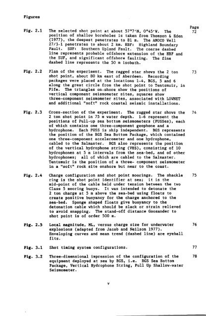
Figures<br />
Fig. 2.1<br />
Fig. 2.2<br />
Fig. 2.3<br />
Fig. 2.4<br />
Fig. 2.5<br />
Fig. 3.1<br />
The selected shot point at about 57°7'N, 0045'V. The<br />
position of shallow boreholes is taken from Thomson & Eden<br />
(1977), the deepest penetrates to 81 m. The AMOCO VeIl<br />
27/3-1 penetrates to about 2 km. HBF: Highland Boundary<br />
Fault. SUF: Southern Upland Fault. The coarse dashed<br />
line represents probable offshore extension of the HBF and<br />
the SUF, and significant offshore faulting. The fine<br />
dashed line represents the 50 m isobath.<br />
Plan of the experiment. The ragged star shows the 2 ton<br />
shot point, about 80 km east of Aberdeen. Recording<br />
packages were placed at the locations 1-4, BGS, 5 and 6<br />
along the great circle from the shot point to Tentsmuir, in<br />
Fife. The triangles on-shore show the positions of<br />
vertical component seismometer sites, squares show<br />
three-component seismometer sites, associated with LOYNET<br />
and additional "soft" rock coastal seismic installations.<br />
Cross-section of the experiment. The ragged star shows the<br />
2 ton shot point in 75 m water depth. 1-6 represent the<br />
positions of Pull-up sea bottom seismometers (PUSSes), each<br />
of which contains one three-component geophone and a<br />
hydrophone. Each PUSS is ship independent. BGS represents<br />
the position of the BGS Sea Bottom Package, which contained<br />
one three-component accelerometer and one hydrophone,<br />
cabled to the Salmaster. BGS also represents the position<br />
of the vertical hydrophone string (VHS), consisting of 10<br />
hydrophones at 5 m intervals from the sea-bed, and of other<br />
hydrophones; all of which are cabled to the Salmaster.<br />
Tentsmuir is the position of a three- component seismometer<br />
in a "soft" rock site onshore but near to the coast.<br />
Charge configuration and shot point moorings. The shackle<br />
ring is the shot point identifier at sea; it is the<br />
mid-point of the cable held under tension between the two<br />
Class 5 mooring buoys. It was intended to detonate the<br />
2 ton charge at 5 m above the sea-bed using floats to<br />
create positive buoyancy for the charge anchored to the<br />
sea-bed. Sponge shaped floats give buoyancy to the<br />
detonation cable which should be slack or strain relieved<br />
to avoid snapping. The stand-off distance Goosander to<br />
shot point is of order 500 m.<br />
Local magnitude, ML, versus charge size for underwater<br />
explosions (adapted from Jacob and Neilson 1977).<br />
Enveloping curves and mean trend (dashed line) are eyeball<br />
fits.<br />
Shot timing system configurations.<br />
Fig. 3.2 Three-dimensional impression of the configuration of the 78<br />
equipment deployed at sea by BGS, i.e. BGS Sea Bottom<br />
Package, Vertical Hydrophone String, Pull Up Shallow-water<br />
Seismometer.<br />
v<br />
Page<br />
72<br />
73<br />
74<br />
75<br />
76<br />
77