

PROFIBUS-DP User Manual for Encoder - heidenhain - DR ...
PROFIBUS-DP User Manual for Encoder - heidenhain - DR ...
PROFIBUS-DP User Manual for Encoder - heidenhain - DR ...

Create successful ePaper yourself
Turn your PDF publications into a flip-book with our unique Google optimized e-Paper software.
Absolute encoder installation<br />
3 Absolute encoder installation<br />
3.1 Settings inside the encoder<br />
3.1.1 Node address<br />
20<br />
The encoder node address and bus termination must be<br />
configured during commissioning of the device. This is done by<br />
removing the back cover, i.e. screwing off the three screws at the<br />
rear of the encoder.<br />
The node address of the encoder can be set via two decimal<br />
rotary switches located inside the back cover. The weighting, x10<br />
or x1 are specified beside the switches. Permissible address<br />
range is between 0 and 99 but the lower addresses 0 to 2 are<br />
usually used by the master and not recommended to be used by<br />
the device. Each address used in a <strong>PROFIBUS</strong> network must be<br />
unique and may not be used by other devices.<br />
The device address is only read and adopted when the encoder<br />
power supply is switched on. A restart of the encoder is there<strong>for</strong>e<br />
required in order to adopt changes done to the address settings.<br />
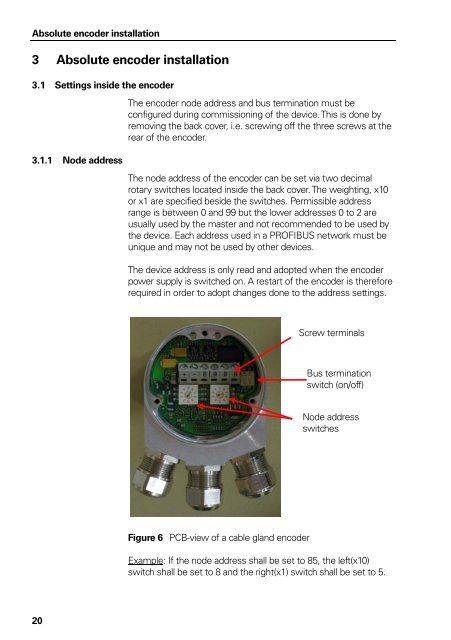
Figure 6 PCB-view of a cable gland encoder<br />
Screw terminals<br />
Bus termination<br />
switch (on/off)<br />
Node address<br />
switches<br />
Example: If the node address shall be set to 85, the left(x10)<br />
switch shall be set to 8 and the right(x1) switch shall be set to 5.


