65-0229 - 7800 SERIES Relay Modules - Greenheck
65-0229 - 7800 SERIES Relay Modules - Greenheck
65-0229 - 7800 SERIES Relay Modules - Greenheck

You also want an ePaper? Increase the reach of your titles
YUMPU automatically turns print PDFs into web optimized ePapers that Google loves.
<strong>7800</strong> <strong>SERIES</strong> RELAY MODULES<br />
<strong>65</strong>-<strong>0229</strong>—1<br />
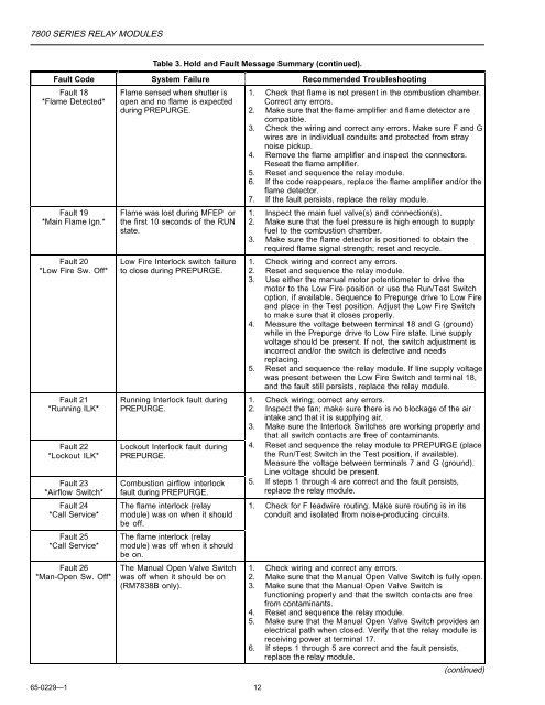
Table 3. Hold and Fault Message Summary (continued).<br />
Fault Code System Failure Recommended Troubleshooting<br />
Fault 18<br />
*Flame Detected*<br />
Fault 19<br />
*Main Flame Ign.*<br />
Fault 20<br />
*Low Fire Sw. Off*<br />
Fault 21<br />
*Running ILK*<br />
Fault 22<br />
*Lockout ILK*<br />
Fault 23<br />
*Airflow Switch*<br />
Fault 24<br />
*Call Service*<br />
Fault 25<br />
*Call Service*<br />
Fault 26<br />
*Man-Open Sw. Off*<br />
Flame sensed when shutter is<br />
open and no flame is expected<br />
during PREPURGE.<br />
Flame was lost during MFEP or<br />
the first 10 seconds of the RUN<br />
state.<br />
Low Fire Interlock switch failure<br />
to close during PREPURGE.<br />
Running Interlock fault during<br />
PREPURGE.<br />
Lockout Interlock fault during<br />
PREPURGE.<br />
Combustion airflow interlock<br />
fault during PREPURGE.<br />
The flame interlock (relay<br />
module) was on when it should<br />
be off.<br />
The flame interlock (relay<br />
module) was off when it should<br />
be on.<br />
The Manual Open Valve Switch<br />
was off when it should be on<br />
(RM7838B only).<br />
1. Check that flame is not present in the combustion chamber.<br />
Correct any errors.<br />
2. Make sure that the flame amplifier and flame detector are<br />
compatible.<br />
3. Check the wiring and correct any errors. Make sure F and G<br />
wires are in individual conduits and protected from stray<br />
noise pickup.<br />
4. Remove the flame amplifier and inspect the connectors.<br />
Reseat the flame amplifier.<br />
5. Reset and sequence the relay module.<br />
6. If the code reappears, replace the flame amplifier and/or the<br />
flame detector.<br />
7. If the fault persists, replace the relay module.<br />
1. Inspect the main fuel valve(s) and connection(s).<br />
2. Make sure that the fuel pressure is high enough to supply<br />
fuel to the combustion chamber.<br />
3. Make sure the flame detector is positioned to obtain the<br />
required flame signal strength; reset and recycle.<br />
1. Check wiring and correct any errors.<br />
2. Reset and sequence the relay module.<br />
3. Use either the manual motor potentiometer to drive the<br />
motor to the Low Fire position or use the Run/Test Switch<br />
option, if available. Sequence to Prepurge drive to Low Fire<br />
and place in the Test position. Adjust the Low Fire Switch<br />
to make sure that it closes properly.<br />
4. Measure the voltage between terminal 18 and G (ground)<br />
while in the Prepurge drive to Low Fire state. Line supply<br />
voltage should be present. If not, the switch adjustment is<br />
incorrect and/or the switch is defective and needs<br />
replacing.<br />
5. Reset and sequence the relay module. If line supply voltage<br />
was present between the Low Fire Switch and terminal 18,<br />
and the fault still persists, replace the relay module.<br />
1. Check wiring; correct any errors.<br />
2. Inspect the fan; make sure there is no blockage of the air<br />
intake and that it is supplying air.<br />
3. Make sure the Interlock Switches are working properly and<br />
12<br />
that all switch contacts are free of contaminants.<br />
4. Reset and sequence the relay module to PREPURGE (place<br />
the Run/Test Switch in the Test position, if available).<br />
Measure the voltage between terminals 7 and G (ground).<br />
Line voltage should be present.<br />
5. If steps 1 through 4 are correct and the fault persists,<br />
replace the relay module.<br />
1. Check for F leadwire routing. Make sure routing is in its<br />
conduit and isolated from noise-producing circuits.<br />
1. Check wiring and correct any errors.<br />
2. Make sure that the Manual Open Valve Switch is fully open.<br />
3. Make sure that the Manual Open Valve Switch is<br />
functioning properly and that the switch contacts are free<br />
from contaminants.<br />
4. Reset and sequence the relay module.<br />
5. Make sure that the Manual Open Valve Switch provides an<br />
electrical path when closed. Verify that the relay module is<br />
receiving power at terminal 17.<br />
6. If steps 1 through 5 are correct and the fault persists,<br />
replace the relay module.<br />
(continued)