65-0229 - 7800 SERIES Relay Modules - Greenheck
65-0229 - 7800 SERIES Relay Modules - Greenheck
65-0229 - 7800 SERIES Relay Modules - Greenheck

You also want an ePaper? Increase the reach of your titles
YUMPU automatically turns print PDFs into web optimized ePapers that Google loves.
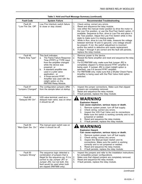
Table 3. Hold and Fault Message Summary (continued).<br />
<strong>7800</strong> <strong>SERIES</strong> RELAY MODULES<br />
Fault Code System Failure Recommended Troubleshooting<br />
Fault 45<br />
*Low Fire Sw. Off*<br />
Fault 46<br />
*Flame Amp Type*<br />
Fault 47<br />
*Jumpers Changed*<br />
Fault 48<br />
*Delayed MV On*<br />
Fault 49<br />
*Man-Open Sw. On.*<br />
Fault 50<br />
*Jumpers Wrong*<br />
Low Fire Interlock switch failure<br />
to close or stay closed.<br />
This fault indicates:<br />
a. The Flame Failure Response<br />
Time (FFRT) or TYPE input<br />
from the amplifier changed<br />
while the device was<br />
powered; or<br />
b. A standard amplifier was<br />
used in a pilot valve<br />
application; or<br />
c. A three-second FFRT<br />
Amplifier was used with the<br />
relight option on the<br />
RM7890 <strong>Relay</strong> Module.<br />
The configuration jumpers differ<br />
from the sample taken at startup.<br />
V2S valve terminal, used as a<br />
delayed main valve, was on when<br />
it should be off.<br />
1. Check wiring; correct any errors.<br />
2. Reset and sequence the relay module.<br />
3. Use either the manual motor position to drive the motor to<br />
the Low Fire position, or use the Run/Test Switch option, if<br />
available. Sequence to Run, drive to Low Fire and place in<br />
the Test position. Adjust the Low Fire Switch while in this<br />
state to make sure it is closing properly.<br />
4. While in Run, drive to Low Fire state, measure the voltage<br />
between terminal 18 and G (ground). Line voltage should<br />
be present. If not, the switch adjustment is incorrect<br />
and/or the switch is defective and needs replacement.<br />
5. If steps 1 through 4 are correct and the fault still persists,<br />
replace the relay module.<br />
1. Remove power to the device.<br />
2. Reseat the flame amplifier and reset and sequence the relay<br />
module.<br />
3. For EC/RM7890 only; make sure that Jumper JR2 is<br />
completely clipped if a three-second FFRT amplifier is<br />
being used. If Jumper JR2 is intact (relight option is<br />
selected), use 0.8 second FFRT amplifier.<br />
4. For RM7838B only; make sure that a Shutter Check Flame<br />
Amplifier is being used with the Pilot Valve Hold option<br />
selected.<br />
1. Inspect the jumper connections. Make sure that clipped<br />
jumpers are completely removed.<br />
2. Reset and sequence the relay module.<br />
3. If fault persists, replace the relay module.<br />
WARNING<br />
Explosion Hazard.<br />
Can cause explosion, serious injury or death.<br />
1. Remove system power, turn off fuel supply.<br />
2. Check wiring; correct any errors.<br />
3. Inspect the V2S Fuel Valve and its connections.<br />
Make sure the switch is working correctly and is not<br />
jumpered or welded.<br />
4. Reset and sequence the relay module.<br />
5. If fault persists, replace the relay module.<br />
The manual open switch was on<br />
when it should be off. WARNING<br />
Explosion Hazard.<br />
Can cause explosion, serious injury or death.<br />
1. Remove system power, turn off fuel supply.<br />
2. Check wiring; correct any errors.<br />
3. Inspect the Manual-Open Switch and its<br />
connections. Make sure the switch is working<br />
correctly and is not jumpered or welded.<br />
4. Reset and sequence the relay module.<br />
5. If fault persists, replace the relay module.<br />
The sequence logic detected a<br />
combination of jumpers that is<br />
illegal for the sequence eg, if it is<br />
correct to clip Jumper JR1 or<br />
Jumper JR2, but not both, this<br />
fault would be used when both<br />
are clipped (RM7888 only).<br />
1. Inspect the jumpers and refer to the installation instructions<br />
for compatible jumper configurations.<br />
2. Make sure that clipped jumpers are completely removed.<br />
3. Reset and sequence the relay module.<br />
4. If fault persists, replace the relay module.<br />
(continued)<br />
15 <strong>65</strong>-<strong>0229</strong>—1