65-0229 - 7800 SERIES Relay Modules - Greenheck
65-0229 - 7800 SERIES Relay Modules - Greenheck
65-0229 - 7800 SERIES Relay Modules - Greenheck

You also want an ePaper? Increase the reach of your titles
YUMPU automatically turns print PDFs into web optimized ePapers that Google loves.
<strong>7800</strong> <strong>SERIES</strong> RELAY MODULES<br />
<strong>65</strong>-<strong>0229</strong>—1<br />
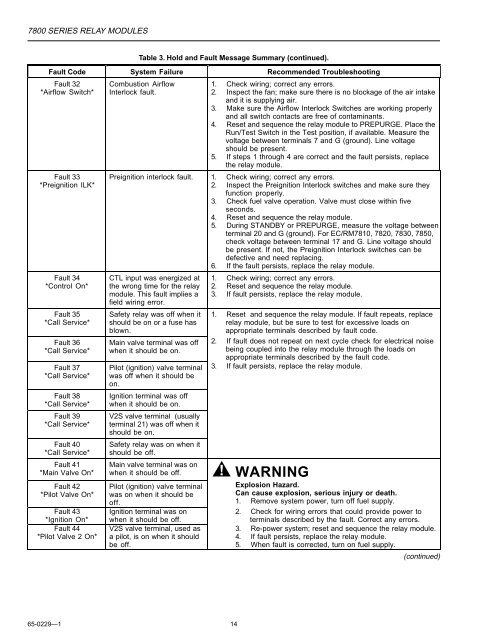
Table 3. Hold and Fault Message Summary (continued).<br />
Fault Code System Failure Recommended Troubleshooting<br />
Fault 32<br />
*Airflow Switch*<br />
Fault 33<br />
*Preignition ILK*<br />
Fault 34<br />
*Control On*<br />
Fault 35<br />
*Call Service*<br />
Fault 36<br />
*Call Service*<br />
Fault 37<br />
*Call Service*<br />
Fault 38<br />
*Call Service*<br />
Fault 39<br />
*Call Service*<br />
Fault 40<br />
*Call Service*<br />
Fault 41<br />
*Main Valve On*<br />
Fault 42<br />
*Pilot Valve On*<br />
Fault 43<br />
*Ignition On*<br />
Fault 44<br />
*Pilot Valve 2 On*<br />
Combustion Airflow<br />
Interlock fault.<br />
1. Check wiring; correct any errors.<br />
2. Inspect the fan; make sure there is no blockage of the air intake<br />
and it is supplying air.<br />
3. Make sure the Airflow Interlock Switches are working properly<br />
and all switch contacts are free of contaminants.<br />
4. Reset and sequence the relay module to PREPURGE. Place the<br />
Run/Test Switch in the Test position, if available. Measure the<br />
voltage between terminals 7 and G (ground). Line voltage<br />
should be present.<br />
5. If steps 1 through 4 are correct and the fault persists, replace<br />
the relay module.<br />
Preignition interlock fault. 1. Check wiring; correct any errors.<br />
2. Inspect the Preignition Interlock switches and make sure they<br />
function properly.<br />
3. Check fuel valve operation. Valve must close within five<br />
seconds.<br />
4. Reset and sequence the relay module.<br />
5. During STANDBY or PREPURGE, measure the voltage between<br />
terminal 20 and G (ground). For EC/RM7810, 7820, 7830, 7850,<br />
check voltage between terminal 17 and G. Line voltage should<br />
be present. If not, the Preignition Interlock switches can be<br />
defective and need replacing.<br />
6. If the fault persists, replace the relay module.<br />
CTL input was energized at<br />
the wrong time for the relay<br />
module. This fault implies a<br />
field wiring error.<br />
Safety relay was off when it<br />
should be on or a fuse has<br />
blown.<br />
Main valve terminal was off<br />
when it should be on.<br />
Pilot (ignition) valve terminal<br />
was off when it should be<br />
on.<br />
Ignition terminal was off<br />
when it should be on.<br />
V2S valve terminal (usually<br />
terminal 21) was off when it<br />
should be on.<br />
Safety relay was on when it<br />
should be off.<br />
1. Check wiring; correct any errors.<br />
2. Reset and sequence the relay module.<br />
3. If fault persists, replace the relay module.<br />
Main valve terminal was on<br />
when it should be off. WARNING<br />
Pilot (ignition) valve terminal<br />
was on when it should be<br />
off.<br />
Ignition terminal was on<br />
when it should be off.<br />
V2S valve terminal, used as<br />
a pilot, is on when it should<br />
be off.<br />
1. Reset and sequence the relay module. If fault repeats, replace<br />
relay module, but be sure to test for excessive loads on<br />
appropriate terminals described by fault code.<br />
2. If fault does not repeat on next cycle check for electrical noise<br />
being coupled into the relay module through the loads on<br />
appropriate terminals described by the fault code.<br />
3. If fault persists, replace the relay module.<br />
Explosion Hazard.<br />
Can cause explosion, serious injury or death.<br />
1. Remove system power, turn off fuel supply.<br />
2. Check for wiring errors that could provide power to<br />
14<br />
terminals described by the fault. Correct any errors.<br />
3. Re-power system; reset and sequence the relay module.<br />
4. If fault persists, replace the relay module.<br />
5. When fault is corrected, turn on fuel supply.<br />
(continued)