65-0229 - 7800 SERIES Relay Modules - Greenheck
65-0229 - 7800 SERIES Relay Modules - Greenheck
65-0229 - 7800 SERIES Relay Modules - Greenheck

Create successful ePaper yourself
Turn your PDF publications into a flip-book with our unique Google optimized e-Paper software.
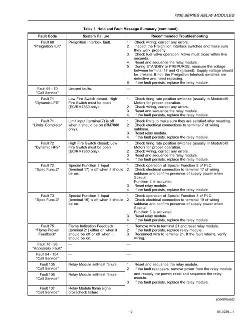
Table 3. Hold and Fault Message Summary (continued).<br />
<strong>7800</strong> <strong>SERIES</strong> RELAY MODULES<br />
Fault Code System Failure Recommended Troubleshooting<br />
Fault 68<br />
*Preignition ILK*<br />
Fault 69 - 70<br />
*Call Service*<br />
Fault 71<br />
*Dynamic LFS*<br />
Fault 71<br />
*Limits Complete*<br />
Fault 72<br />
*Dynamic HFS*<br />
Fault 72<br />
*Spec.Func.2*<br />
Fault 73<br />
*Spec.Func.3*<br />
Fault 75<br />
*Flame Proven<br />
Feedback*<br />
Fault 76 - 93<br />
*Accessory Fault*<br />
Fault 94 - 104<br />
*Call Service*<br />
Fault 105<br />
*Call Service*<br />
Fault 106<br />
*Call Service*<br />
Fault 107<br />
*Call Service*<br />
Preignition Interlock fault. 1. Check wiring; correct any errors.<br />
2. Inspect the Preignition Interlock switches and make sure<br />
they work properly.<br />
3. Check fuel valve operation. Valve must close within five<br />
seconds.<br />
4. Reset and sequence the relay module.<br />
5. During STANDBY or PREPURGE, measure the voltage<br />
between terminal 17 and G (ground). Supply voltage should<br />
be present. If not, the Preignition Interlock switches are<br />
defective and need replacing.<br />
6. If the fault persists, replace the relay module.<br />
Unused faults. ⎯<br />
Low Fire Switch closed, High<br />
Fire Switch must be open<br />
(EC/RM7850 only).<br />
Limit input (terminal 7) is off<br />
when it should be on (RM7888<br />
only).<br />
High Fire Switch closed; Low<br />
Fire Switch must be open<br />
(EC/RM7850 only).<br />
Special Function 2 Input<br />
(terminal 17) is off when it should<br />
be on.<br />
Special Function 3 Input<br />
(terminal 19) is off when it should<br />
be on.<br />
Flame Indication Feedback<br />
(terminal 21) either on when it<br />
should be off or off when it<br />
should be on.<br />
⎯ ⎯<br />
⎯ ⎯<br />
1. Check firing rate position switches (usually in Modutrol®<br />
Motor) for proper operation.<br />
2. Check wiring, correct any errors.<br />
3. Reset and sequence the relay module.<br />
4. If the fault persists, replace the relay module.<br />
1. Check limits to make sure they are satisfied after resetting.<br />
2. Check electrical connections to terminal 7 of wiring<br />
subbase.<br />
3. Reset relay module.<br />
4. If the fault persists, replace the relay module.<br />
1. Check firing rate position switches (usually in Modutrol®<br />
Motor) for proper operation.<br />
2. Check wiring, correct any errors.<br />
3. Reset and sequence the relay module.<br />
4. If the fault persists, replace the relay module.<br />
1. Check operation of Special Function 2 of PLC.<br />
2. Check electrical connection to terminal 17 of wiring<br />
subbase and confirm presence of supply power when<br />
Special<br />
Function 2 is activated.<br />
3. Reset relay module.<br />
4. If the fault persists, replace the relay module.<br />
1. Check operation of Special Function 3 of PLC.<br />
2. Check electrical connection to terminal 19 of wiring<br />
subbase and confirm presence of supply power when<br />
Special<br />
Function 3 is activated.<br />
3. Reset relay module.<br />
4. If the fault persists, replace the relay module.<br />
1. Remove wire to terminal 21 and reset relay module.<br />
2. If the fault persists, replace relay module.<br />
3. Reconnect wire to terminal 21. If the fault returns, verify<br />
wiring.<br />
<strong>Relay</strong> Module self-test failure. 1. Reset and sequence the relay module.<br />
2. If the fault reappears, remove power from the relay module<br />
<strong>Relay</strong> Module self-test failure. and reapply the power; reset and sequence the relay<br />
module.<br />
<strong>Relay</strong> Module flame signal<br />
crosscheck failure.<br />
3. If the fault persists, replace the relay module.<br />
(continued)<br />
17 <strong>65</strong>-<strong>0229</strong>—1