DE2-70 Manual - Computation Structures Group
DE2-70 Manual - Computation Structures Group
DE2-70 Manual - Computation Structures Group

Create successful ePaper yourself
Turn your PDF publications into a flip-book with our unique Google optimized e-Paper software.
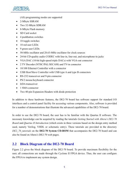
(AS) programming modes are supported<br />
• 2-Mbyte SSRAM<br />
• Two 32-Mbyte SDRAM<br />
• 8-Mbyte Flash memory<br />
• SD Card socket<br />
• 4 pushbutton switches<br />
• 18 toggle switches<br />
• 18 red user LEDs<br />
• 9 green user LEDs<br />
• 50-MHz oscillator and 28.63-MHz oscillator for clock sources<br />
• 24-bit CD-quality audio CODEC with line-in, line-out, and microphone-in jacks<br />
• VGA DAC (10-bit high-speed triple DACs) with VGA-out connector<br />
• 2 TV Decoder (NTSC/PAL/SECAM) and TV-in connector<br />
• 10/100 Ethernet Controller with a connector<br />
• USB Host/Slave Controller with USB type A and type B connectors<br />
• RS-232 transceiver and 9-pin connector<br />
• PS/2 mouse/keyboard connector<br />
• IrDA transceiver<br />
• 1 SMA connector<br />
• Two 40-pin Expansion Headers with diode protection<br />
5<br />
<strong>DE2</strong>-<strong>70</strong> User <strong>Manual</strong><br />
In addition to these hardware features, the <strong>DE2</strong>-<strong>70</strong> board has software support for standard I/O<br />
interfaces and a control panel facility for accessing various components. Also, software is provided<br />
for a number of demonstrations that illustrate the advanced capabilities of the <strong>DE2</strong>-<strong>70</strong> board.<br />
In order to use the <strong>DE2</strong>-<strong>70</strong> board, the user has to be familiar with the Quartus II software. The<br />
necessary knowledge can be acquired by reading the tutorials Getting Started with Altera’s <strong>DE2</strong>-<strong>70</strong><br />
Board and Quartus II Introduction (which exists in three versions based on the design entry method<br />
used, namely Verilog, VHDL or schematic entry). These tutorials are provided in the directory<br />
<strong>DE2</strong>_<strong>70</strong>_tutorials on the <strong>DE2</strong>-<strong>70</strong> System CD-ROM that accompanies the <strong>DE2</strong>-<strong>70</strong> board and can<br />
also be found on Altera’s <strong>DE2</strong>-<strong>70</strong> web pages.<br />
2.2 Block Diagram of the <strong>DE2</strong>-<strong>70</strong> Board<br />
Figure 2.2 gives the block diagram of the <strong>DE2</strong>-<strong>70</strong> board. To provide maximum flexibility for the<br />
user, all connections are made through the Cyclone II FPGA device. Thus, the user can configure<br />
the FPGA to implement any system design.