DE2-70 Manual - Computation Structures Group
DE2-70 Manual - Computation Structures Group
DE2-70 Manual - Computation Structures Group

You also want an ePaper? Increase the reach of your titles
YUMPU automatically turns print PDFs into web optimized ePapers that Google loves.
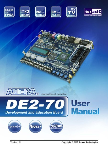
Altera <strong>DE2</strong>-<strong>70</strong> Board<br />
Version 1.01 Copyright © 2007 Terasic Technologies
Altera <strong>DE2</strong> Board<br />
CONTENTS<br />
Chapter 1 <strong>DE2</strong>-<strong>70</strong> Package ...............................................................................................................1<br />
1.1 Package Contents .................................................................................................................1<br />
1.2 The <strong>DE2</strong>-<strong>70</strong> Board Assembly ..............................................................................................2<br />
1.3 Getting Help.........................................................................................................................3<br />
Chapter 2 Altera <strong>DE2</strong>-<strong>70</strong> Board .......................................................................................................4<br />
2.1 Layout and Components ......................................................................................................4<br />
2.2 Block Diagram of the <strong>DE2</strong>-<strong>70</strong> Board ..................................................................................5<br />
2.3 Power-up the <strong>DE2</strong>-<strong>70</strong> Board................................................................................................9<br />
Chapter 3 <strong>DE2</strong>-<strong>70</strong> Control Panel.................................................................................................... 11<br />
3.1 Control Panel Setup ...........................................................................................................11<br />
3.2 Controlling the LEDs, 7-Segment Displays and LCD Display .........................................13<br />
3.3 Switches and Buttons.........................................................................................................15<br />
3.4 SDRAM/SSRAM/Flash Controller and Programmer........................................................16<br />
3.5 USB Monitoring.................................................................................................................18<br />
3.6 PS2 Device.........................................................................................................................19<br />
3.7 SD CARD ..........................................................................................................................20<br />
3.8 Audio Playing and Recording............................................................................................21<br />
3.9 Overall Structure of the <strong>DE2</strong>-<strong>70</strong> Control Panel .................................................................23<br />
Chapter 4 <strong>DE2</strong>-<strong>70</strong> Video Utility......................................................................................................25<br />
4.1 Video Utility Setup.............................................................................................................25<br />
4.2 VGA Display......................................................................................................................26<br />
4.3 Video Capture ....................................................................................................................27<br />
4.4 Overall Structure of the <strong>DE2</strong>-<strong>70</strong> Video Utility ..................................................................28<br />
Chapter 5 Using the <strong>DE2</strong>-<strong>70</strong> Board................................................................................................30<br />
5.1 Configuring the Cyclone II FPGA.....................................................................................30<br />
5.2 Using the LEDs and Switches............................................................................................32<br />
5.3 Using the 7-segment Displays............................................................................................36<br />
5.4 Clock Circuitry...................................................................................................................38<br />
5.5 Using the LCD Module......................................................................................................40<br />
5.6 Using the Expansion Header..............................................................................................41<br />
5.7 Using VGA ........................................................................................................................45<br />
5.8 Using the 24-bit Audio CODEC ........................................................................................48<br />
5.9 RS-232 Serial Port .............................................................................................................49<br />
5.10 PS/2 Serial Port ..................................................................................................................49<br />
5.11 Fast Ethernet Network Controller......................................................................................50<br />
ii
Altera <strong>DE2</strong> Board<br />
5.12 TV Decoder........................................................................................................................52<br />
5.13 Implementing a TV Encoder..............................................................................................54<br />
5.14 Using USB Host and Device..............................................................................................55<br />
5.15 Using IrDA.........................................................................................................................56<br />
5.16 Using SDRAM/SRAM/Flash.............................................................................................57<br />
Chapter 6 Examples of Advanced Demonstrations ......................................................................66<br />
6.1 <strong>DE2</strong>-<strong>70</strong> Factory Configuration ..........................................................................................66<br />
6.2 TV Box Demonstration......................................................................................................67<br />
6.3 TV Box Picture in Picture (PIP) Demonstration................................................................69<br />
6.4 USB Paintbrush..................................................................................................................72<br />
6.5 USB Device........................................................................................................................74<br />
6.6 A Karaoke Machine ...........................................................................................................76<br />
6.7 Ethernet Packet Sending/Receiving...................................................................................78<br />
6.8 SD Card Music Player........................................................................................................80<br />
6.9 Music Synthesizer Demonstration .....................................................................................83<br />
6.10 Audio Recording and Playing............................................................................................87<br />
Chapter 7 Appendix .........................................................................................................................90<br />
7.1 Revision History ................................................................................................................90<br />
7.2 Copyright Statement ..........................................................................................................90<br />
iii
Chapter 1<br />
<strong>DE2</strong>-<strong>70</strong> Package<br />
1<br />
<strong>DE2</strong>-<strong>70</strong> User <strong>Manual</strong><br />
The <strong>DE2</strong>-<strong>70</strong> package contains all components needed to use the <strong>DE2</strong>-<strong>70</strong> board in conjunction with<br />
a computer that runs the Microsoft Windows software.<br />
1.1 Package Contents<br />
Figure 1.1 shows a photograph of the <strong>DE2</strong>-<strong>70</strong> package.<br />
Figure 1.1. The <strong>DE2</strong>-<strong>70</strong> package contents.
The <strong>DE2</strong>-<strong>70</strong> package includes:<br />
• The <strong>DE2</strong>-<strong>70</strong> board<br />
• USB Cable for FPGA programming and control<br />
2<br />
<strong>DE2</strong>-<strong>70</strong> User <strong>Manual</strong><br />
• <strong>DE2</strong>-<strong>70</strong> System CD containing the <strong>DE2</strong>-<strong>70</strong> documentation and supporting materials,<br />
including the User <strong>Manual</strong>, the Control Panel utility, reference designs and demonstrations,<br />
device datasheets, tutorials, and a set of laboratory exercises<br />
• CD-ROMs containing Altera’s Quartus ® II Web Edition and the Nios ® II Embedded Design<br />
Suit Evaluation Edition software.<br />
• Bag of six rubber (silicon) covers for the <strong>DE2</strong>-<strong>70</strong> board stands. The bag also contains some<br />
extender pins, which can be used to facilitate easier probing with testing equipment of the<br />
board’s I/O expansion headers<br />
• Clear plastic cover for the board<br />
• 12V DC wall-mount power supply<br />
1.2 The <strong>DE2</strong>-<strong>70</strong> Board Assembly<br />
To assemble the included stands for the <strong>DE2</strong>-<strong>70</strong> board:<br />
• Assemble a rubber (silicon) cover, as shown in Figure 1.2, for each of the six copper stands<br />
on the <strong>DE2</strong>-<strong>70</strong> board<br />
• The clear plastic cover provides extra protection, and is mounted over the top of the board<br />
by using additional stands and screws<br />
Figure 1.2. The feet for the <strong>DE2</strong>-<strong>70</strong> board.
1.3 Getting Help<br />
Here are the addresses where you can get help if you encounter problems:<br />
• Altera Corporation<br />
101 Innovation Drive<br />
San Jose, California, 95134 USA<br />
Email: university@altera.com<br />
• Terasic Technologies<br />
No. 356, Sec. 1, Fusing E. Rd.<br />
Jhubei City, HsinChu County, Taiwan, 302<br />
Email: support@terasic.com<br />
Web: <strong>DE2</strong>-<strong>70</strong>.terasic.com<br />
3<br />
<strong>DE2</strong>-<strong>70</strong> User <strong>Manual</strong>
Chapter 2<br />
Altera <strong>DE2</strong>-<strong>70</strong> Board<br />
This chapter presents the features and design characteristics of the <strong>DE2</strong>-<strong>70</strong> board.<br />
2.1 Layout and Components<br />
4<br />
<strong>DE2</strong>-<strong>70</strong> User <strong>Manual</strong><br />
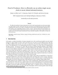
A photograph of the <strong>DE2</strong>-<strong>70</strong> board is shown in Figure 2.1. It depicts the layout of the board and<br />
indicates the location of the connectors and key components.<br />
12V DC Power Supply<br />
Connector<br />
Power ON/OFF Switch<br />
USB Host/Slave<br />
Controller<br />
Audio CODEC<br />
Altera USB Blaster<br />
Controller chipset<br />
Altera EPCS16<br />
Configuration Device<br />
RUN/PROG Switch for<br />
JTAG/AS Modes<br />
16x2 LCD Module<br />
7-Segment Displays<br />
18 Red LEDs<br />
18 Toggle Switches<br />
USB Blaster Port<br />
USB Device Port<br />
USB Host Port<br />
Mic in Line In Line Out<br />
Video In 1 Video In 2<br />
VGA Out<br />
Ethernet 10/100M Port<br />
RS-232 Port<br />
32Mbyte SDRAMx2 28Mhz Oscillator 2Mbyte SSRAM 4 Push-button Switches<br />
Figure 2.1. The <strong>DE2</strong>-<strong>70</strong> board.<br />
TV TV Decoder (NTSC/PAL) X2<br />
PS2 Port<br />
VGA 10-bit DAC<br />
Ethernet 10/100M Controller<br />
50Mhz Oscillator<br />
Expansion Header 2<br />
Expansion Header 1<br />
SD Card Slot<br />
Lock<br />
(SD Card Not Included)<br />
Altera Cyclone II<br />
FPGA with <strong>70</strong>K LEs<br />
IrDA Transceiver<br />
8Mbyte Flash Memory<br />
8 Green LEDs<br />
SMA Extemal Clock<br />
The <strong>DE2</strong>-<strong>70</strong> board has many features that allow the user to implement a wide range of designed<br />
circuits, from simple circuits to various multimedia projects.<br />
The following hardware is provided on the <strong>DE2</strong>-<strong>70</strong> board:<br />
• Altera Cyclone ® II 2C<strong>70</strong> FPGA device<br />
• Altera Serial Configuration device - EPCS16<br />
• USB Blaster (on board) for programming and user API control; both JTAG and Active Serial
(AS) programming modes are supported<br />
• 2-Mbyte SSRAM<br />
• Two 32-Mbyte SDRAM<br />
• 8-Mbyte Flash memory<br />
• SD Card socket<br />
• 4 pushbutton switches<br />
• 18 toggle switches<br />
• 18 red user LEDs<br />
• 9 green user LEDs<br />
• 50-MHz oscillator and 28.63-MHz oscillator for clock sources<br />
• 24-bit CD-quality audio CODEC with line-in, line-out, and microphone-in jacks<br />
• VGA DAC (10-bit high-speed triple DACs) with VGA-out connector<br />
• 2 TV Decoder (NTSC/PAL/SECAM) and TV-in connector<br />
• 10/100 Ethernet Controller with a connector<br />
• USB Host/Slave Controller with USB type A and type B connectors<br />
• RS-232 transceiver and 9-pin connector<br />
• PS/2 mouse/keyboard connector<br />
• IrDA transceiver<br />
• 1 SMA connector<br />
• Two 40-pin Expansion Headers with diode protection<br />
5<br />
<strong>DE2</strong>-<strong>70</strong> User <strong>Manual</strong><br />
In addition to these hardware features, the <strong>DE2</strong>-<strong>70</strong> board has software support for standard I/O<br />
interfaces and a control panel facility for accessing various components. Also, software is provided<br />
for a number of demonstrations that illustrate the advanced capabilities of the <strong>DE2</strong>-<strong>70</strong> board.<br />
In order to use the <strong>DE2</strong>-<strong>70</strong> board, the user has to be familiar with the Quartus II software. The<br />
necessary knowledge can be acquired by reading the tutorials Getting Started with Altera’s <strong>DE2</strong>-<strong>70</strong><br />
Board and Quartus II Introduction (which exists in three versions based on the design entry method<br />
used, namely Verilog, VHDL or schematic entry). These tutorials are provided in the directory<br />
<strong>DE2</strong>_<strong>70</strong>_tutorials on the <strong>DE2</strong>-<strong>70</strong> System CD-ROM that accompanies the <strong>DE2</strong>-<strong>70</strong> board and can<br />
also be found on Altera’s <strong>DE2</strong>-<strong>70</strong> web pages.<br />
2.2 Block Diagram of the <strong>DE2</strong>-<strong>70</strong> Board<br />
Figure 2.2 gives the block diagram of the <strong>DE2</strong>-<strong>70</strong> board. To provide maximum flexibility for the<br />
user, all connections are made through the Cyclone II FPGA device. Thus, the user can configure<br />
the FPGA to implement any system design.
Figure 2.2. Block diagram of the <strong>DE2</strong>-<strong>70</strong> board.<br />
Following is more detailed information about the blocks in Figure 2.2:<br />
Cyclone II 2C<strong>70</strong> FPGA<br />
• 68,416 LEs<br />
• 250 M4K RAM blocks<br />
• 1,152,000 total RAM bits<br />
• 150 embedded multipliers<br />
• 4 PLLs<br />
• 622 user I/O pins<br />
• FineLine BGA 896-pin package<br />
Serial Configuration device and USB Blaster circuit<br />
• Altera’s EPCS16 Serial Configuration device<br />
• On-board USB Blaster for programming and user API control<br />
• JTAG and AS programming modes are supported<br />
6<br />
<strong>DE2</strong>-<strong>70</strong> User <strong>Manual</strong>
SSRAM<br />
• 2-Mbyte standard synchronous SRAM<br />
• Organized as 512K x 36 bits<br />
• Accessible as memory for the Nios II processor and by the <strong>DE2</strong>-<strong>70</strong> Control Panel<br />
SDRAM<br />
• Two 32-Mbyte Single Data Rate Synchronous Dynamic RAM memory chips<br />
• Organized as 4M x 16 bits x 4 banks<br />
• Accessible as memory for the Nios II processor and by the <strong>DE2</strong>-<strong>70</strong> Control Panel<br />
Flash memory<br />
• 8-Mbyte NOR Flash memory<br />
• Support both byte and word mode access<br />
• Accessible as memory for the Nios II processor and by the <strong>DE2</strong>-<strong>70</strong> Control Panel<br />
SD card socket<br />
• Provides SPI and 1-bit SD mode for SD Card access<br />
• Accessible as memory for the Nios II processor with the <strong>DE2</strong>-<strong>70</strong> SD Card Driver<br />
Pushbutton switches<br />
• 4 pushbutton switches<br />
• Debounced by a Schmitt trigger circuit<br />
• Normally high; generates one active-low pulse when the switch is pressed<br />
Toggle switches<br />
• 18 toggle switches for user inputs<br />
7<br />
<strong>DE2</strong>-<strong>70</strong> User <strong>Manual</strong><br />
• A switch causes logic 0 when in the DOWN (closest to the edge of the <strong>DE2</strong>-<strong>70</strong> board)<br />
position and logic 1 when in the UP position<br />
Clock inputs<br />
• 50-MHz oscillator<br />
• 28.63-MHz oscillator<br />
• SMA external clock input
8<br />
<strong>DE2</strong>-<strong>70</strong> User <strong>Manual</strong><br />
Audio CODEC<br />
• Wolfson WM8731 24-bit sigma-delta audio CODEC<br />
• Line-level input, line-level output, and microphone input jacks<br />
• Sampling frequency: 8 to 96 KHz<br />
• Applications for MP3 players and recorders, PDAs, smart phones, voice recorders, etc.<br />
VGA output<br />
• Uses the ADV7123 240-MHz triple 10-bit high-speed video DAC<br />
• With 15-pin high-density D-sub connector<br />
• Supports up to 1600 x 1200 at 100-Hz refresh rate<br />
• Can be used with the Cyclone II FPGA to implement a high-performance TV Encoder<br />
NTSC/PAL/ SECAM TV decoder circuit<br />
• Uses two ADV7180 Multi-format SDTV Video Decoders<br />
• Supports worldwide NTSC/PAL/SECAM color demodulation<br />
• One 10-bit ADC, 4X over-sampling for CVBS<br />
• Supports Composite Video (CVBS) RCA jack input<br />
• Supports digital output formats : 8-bit ITU-R BT.656 YCrCb 4:2:2 output + HS, VS, and<br />
FIELD<br />
• Applications: DVD recorders, LCD TV, Set-top boxes, Digital TV, Portable video devices,<br />
and TV PIP (picture in picture) display.<br />
10/100 Ethernet controller<br />
• Integrated MAC and PHY with a general processor interface<br />
• Supports 100Base-T and 10Base-T applications<br />
• Supports full-duplex operation at 10 Mb/s and 100 Mb/s, with auto-MDIX<br />
• Fully compliant with the IEEE 802.3u Specification<br />
• Supports IP/TCP/UDP checksum generation and checking<br />
• Supports back-pressure mode for half-duplex mode flow control<br />
USB Host/Slave controller<br />
• Complies fully with Universal Serial Bus Specification Rev. 2.0<br />
• Supports data transfer at full-speed and low-speed<br />
• Supports both USB host and device<br />
• Two USB ports (one type A for a host and one type B for a device)<br />
• Provides a high-speed parallel interface to most available processors; supports Nios II with a<br />
Terasic driver<br />
• Supports Programmed I/O (PIO) and Direct Memory Access (DMA)
Serial ports<br />
• One RS-232 port<br />
• One PS/2 port<br />
• DB-9 serial connector for the RS-232 port<br />
• PS/2 connector for connecting a PS2 mouse or keyboard to the <strong>DE2</strong>-<strong>70</strong> board<br />
IrDA transceiver<br />
• Contains a 115.2-kb/s infrared transceiver<br />
• 32 mA LED drive current<br />
• Integrated EMI shield<br />
• IEC825-1 Class 1 eye safe<br />
• Edge detection input<br />
9<br />
<strong>DE2</strong>-<strong>70</strong> User <strong>Manual</strong><br />
Two 40-pin expansion headers<br />
• 72 Cyclone II I/O pins, as well as 8 power and ground lines, are brought out to two 40-pin<br />
expansion connectors<br />
• 40-pin header is designed to accept a standard 40-pin ribbon cable used for IDE hard drives<br />
• Diode and resistor protection is provided<br />
2.3 Power-up the <strong>DE2</strong>-<strong>70</strong> Board<br />
The <strong>DE2</strong>-<strong>70</strong> board comes with a preloaded configuration bit stream to demonstrate some features of<br />
the board. This bit stream also allows users to see quickly if the board is working properly. To<br />
power-up the board perform the following steps:<br />
1. Connect the provided USB cable from the host computer to the USB Blaster connector on<br />
the <strong>DE2</strong>-<strong>70</strong> board. For communication between the host and the <strong>DE2</strong>-<strong>70</strong> board, it is<br />
necessary to install the Altera USB Blaster driver software. If this driver is not already<br />
installed on the host computer, it can be installed as explained in the tutorial Getting<br />
Started with Altera's <strong>DE2</strong>-<strong>70</strong> Board. This tutorial is available in the directory<br />
<strong>DE2</strong>_<strong>70</strong>_tutorials on the <strong>DE2</strong>-<strong>70</strong> System CD-ROM.<br />
2. Connect the 12V adapter to the <strong>DE2</strong>-<strong>70</strong> board<br />
3. Connect a VGA monitor to the VGA port on the <strong>DE2</strong>-<strong>70</strong> board<br />
4. Connect your headset to the Line-out audio port on the <strong>DE2</strong>-<strong>70</strong> board<br />
5. Turn the RUN/PROG switch on the left edge of the <strong>DE2</strong>-<strong>70</strong> board to RUN position; the<br />
PROG position is used only for the AS Mode programming<br />
6. Turn the power on by pressing the ON/OFF switch on the <strong>DE2</strong>-<strong>70</strong> board
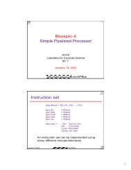
At this point you should observe the following:<br />
• All user LEDs are flashing<br />
• All 7-segment displays are cycling through the numbers 0 to F<br />
• The LCD display shows Welcome to the Altera <strong>DE2</strong>-<strong>70</strong><br />
• The VGA monitor displays the image shown in Figure 2.3.<br />
• Set the toggle switch SW17 to the DOWN position; you should hear a 1-kHz sound<br />
10<br />
<strong>DE2</strong>-<strong>70</strong> User <strong>Manual</strong><br />
• Set the toggle switch SW17 to the UP position and connect the output of an audio player to<br />
the Line-in connector on the <strong>DE2</strong>-<strong>70</strong> board; on your headset you should hear the music<br />
played from the audio player (MP3, PC, iPod, or the like)<br />
• You can also connect a microphone to the Microphone-in connector on the <strong>DE2</strong>-<strong>70</strong> board;<br />
your voice will be mixed with the music played from the audio player<br />
Figure 2.3. The default VGA output pattern.
Chapter 3<br />
<strong>DE2</strong>-<strong>70</strong> Control Panel<br />
11<br />
<strong>DE2</strong>-<strong>70</strong> User <strong>Manual</strong><br />
The <strong>DE2</strong>-<strong>70</strong> board comes with a Control Panel facility that allows users to access various<br />
components on the board from a host computer. The host computer communicates with the board<br />
through an USB connection. The facility can be used to verify the functionality of components on<br />
the board or be used as a debug tool while developing RTL code.<br />
This chapter first presents some basic functions of the Control Panel, then describes its structure in<br />
block diagram form, and finally describes its capabilities.<br />
.<br />
3.1 Control Panel Setup<br />
The Control Panel Software Utility is located in the “<strong>DE2</strong>_<strong>70</strong>_control_pane/SW” folder in the<br />
<strong>DE2</strong>-<strong>70</strong> System CD-ROM. To install it, just copy the whole folder to your host computer. Launch<br />
the control panel by executing the “<strong>DE2</strong>_<strong>70</strong>_Control_Panel.exe”.<br />
Specific control codes should be downloaded to your FPGA board before the control panel can<br />
request it to perform required tasks. The control codes include one .sof file and one .elf file. To<br />
download the codes, just click the “Download Code” button on the program. The program will call<br />
Quartus II and Nios II tools to download the control codes to the FPGA board through<br />
USB-Blaster[USB-0] connection. The .sof file is downloaded to FPGA. The .elf file is downloaded<br />
to either SDRAM-U2 or SSRAM, according to the user option.<br />
To activate the Control Panel, perform the following steps:<br />
1. Make sure Quartus II and NIOS II are installed successfully on your PC.<br />
2. Connect the supplied USB cable to the USB Blaster port, connect the 12V power supply,<br />
and turn the power switch ON<br />
3. Set the RUN/PROG switch to the RUN position<br />
4. Start the executable <strong>DE2</strong>_<strong>70</strong>_control_panel.exe on the host computer. The Control Panel<br />
user interface shown in Figure 3.1 will appear.<br />
5. Select the target memory, SDRAM-U2 or SSRAM, on the control panel. Note. The .elf file<br />
will be downloaded to the target memory and the memory will be read-only in later<br />
memory access operation.<br />
6. Click Download Code button. Note, the Control Panel will occupy the USB port until you
12<br />
<strong>DE2</strong>-<strong>70</strong> User <strong>Manual</strong><br />
close that port; you cannot use Quartus II to download a configuration file into the FPGA<br />
until you close the USB port.<br />
7. The Control Panel is now ready for use; experiment by setting the value of some LEDs<br />
display and observing the result on the <strong>DE2</strong>-<strong>70</strong> board.<br />
Figure 3.1. The <strong>DE2</strong>-<strong>70</strong> Control Panel.<br />
The concept of the <strong>DE2</strong>-<strong>70</strong> Control Panel is illustrated in Figure 3.2. The “Control Codes” that<br />
performs the control functions is implemented in the FPGA board. It communicates with the<br />
Control Panel window, which is active on the host computer, via the USB Blaster link. The<br />
graphical interface is used to issue commands to the control codes. It handles all requests and<br />
performs data transfers between the computer and the <strong>DE2</strong>-<strong>70</strong> board.
USB<br />
Blaster<br />
13<br />
7-SEG Display<br />
Control<br />
Codes<br />
LEDs<br />
Figure 3.2. The <strong>DE2</strong>-<strong>70</strong> Control Panel concept.<br />
<strong>DE2</strong>-<strong>70</strong> User <strong>Manual</strong><br />
16x2<br />
LCD<br />
SDRAM<br />
Flash<br />
SSRAM<br />
PS/2<br />
USB<br />
Device<br />
SD Card<br />
Soket<br />
The <strong>DE2</strong>-<strong>70</strong> Control Panel can be used to light up LEDs, change the values displayed on 7-segment<br />
and LCD displays, monitor buttons/switches status, read/write the SDRAM, SSRAM and Flash<br />
Memory, monitor the status of an USB mouse, read data from a PS/2 keyboard, and read SD-CARD<br />
specification information. The feature of reading/writing a word or an entire file from/to the Flash<br />
Memory allows the user to develop multimedia applications (Flash Audio Player, Flash Picture<br />
Viewer) without worrying about how to build a Memory Programmer.<br />
3.2 Controlling the LEDs, 7-Segment Displays and LCD Display<br />
A simple function of the Control Panel is to allow setting the values displayed on LEDs, 7-segment<br />
displays, and the LCD character display.<br />
Choosing the LED tab leads to the window in Figure 3.3. Here, you can directly turn the individual<br />
LEDs on or off by selecting them or click “Light All” or “Unlight All”.
Figure 3.3. Controlling LEDs.<br />
14<br />
<strong>DE2</strong>-<strong>70</strong> User <strong>Manual</strong><br />
Choosing the 7-SEG tab leads to the window in Figure 3.4. In the tab sheet, directly use the<br />
Up-Down control and Dot Check box to specified desired patterns, the 7-SEG patterns on the board<br />
will be updated immediately.<br />
Figure 3.4. Controlling 7-SEG display.
15<br />
<strong>DE2</strong>-<strong>70</strong> User <strong>Manual</strong><br />
Choosing the LCD tab leads to the window in Figure 3.5. Text can be written to the LCD display by<br />
typing it in the LCD box and pressing the Set button.<br />
Figure 3.5. Controlling LEDs and the LCD display.<br />
The ability to set arbitrary values into simple display devices is not needed in typical design<br />
activities. However, it gives the user a simple mechanism for verifying that these devices are<br />
functioning correctly in case a malfunction is suspected. Thus, it can be used for troubleshooting<br />
purposes.<br />
3.3 Switches and Buttons<br />
Choosing the Button tab leads to the window in Figure 3.6. The function is designed to monitor the<br />
status of switches and buttons in real time and show the status in a graphical user interface. It can be<br />
used to verify the functionality of the switches and buttons.<br />
Press the Start button to start button/switch status monitoring process, and button caption is<br />
changed from Start to Stop. In the monitoring process, the status of buttons and switches on the<br />
board is shown in the GUI window and updated in real time. Press Stop to end the monitoring<br />
process.
Figure 3.6. Monitoring switches and buttons.<br />
16<br />
<strong>DE2</strong>-<strong>70</strong> User <strong>Manual</strong><br />
The ability to check the status of button and switch is not needed in typical design activities.<br />
However, it provides users a simple mechanism for verifying if the buttons and switches are<br />
functioning correctly. Thus, it can be used for troubleshooting purposes.<br />
3.4 SDRAM/SSRAM/Flash Controller and Programmer<br />
The Control Panel can be used to write/read data to/from the SDRAM, SSRAM, and FLASH chips<br />
on the <strong>DE2</strong>-<strong>70</strong> board. We will describe how the SDRAM-U1 may be accessed; the same approach<br />
is used to access the SDRAM-U2, SRAM, and FLASH. Click on the Memory tab and select<br />
“SDRAM-U1” to reach the window in Figure 3.7. Please note the target memory chosen for<br />
storing .elf file is read-only. Also, please erase the flash before writing data to it.
Figure 3.7. Accessing the SDRAM-U1.<br />
<strong>DE2</strong>-<strong>70</strong> User <strong>Manual</strong><br />
A 16-bit word can be written into the SDRAM by entering the address of the desired location,<br />
specifying the data to be written, and pressing the Write button. Contents of the location can be<br />
read by pressing the Read button. Figure 3.7 depicts the result of writing the hexadecimal value<br />
06CA into location 200, followed by reading the same location.<br />
The Sequential Write function of the Control Panel is used to write the contents of a file into the<br />
SDRAM as follows:<br />
1. Specify the starting address in the Address box.<br />
2. Specify the number of bytes to be written in the Length box. If the entire file is to be<br />
loaded, then a checkmark may be placed in the File Length box instead of giving the<br />
number of bytes.<br />
3. To initiate the writing of data, click on the Write a File to Memory button.<br />
4. When the Control Panel responds with the standard Windows dialog box asking for the<br />
source file, specify the desired file in the usual manner.<br />
The Control Panel also supports loading files with a .hex extension. Files with a .hex extension are<br />
ASCII text files that specify memory values using ASCII characters to represent hexadecimal<br />
values. For example, a file containing the line<br />
0123456789ABCDEF<br />
defines four 8-bit values: 01, 23, 45, 67, 89, AB, CD, EF. These values will be loaded consecutively<br />
17
into the memory.<br />
18<br />
<strong>DE2</strong>-<strong>70</strong> User <strong>Manual</strong><br />
The Sequential Read function is used to read the contents of the SDRAM-U1 and place them into a<br />
file as follows:<br />
1. Specify the starting address in the Address box.<br />
2. Specify the number of bytes to be copied into the file in the Length box. If the entire<br />
contents of the SDRAM-U1 are to be copied (which involves all 32 Mbytes), then place a<br />
checkmark in the Entire Memory box.<br />
3. Press Load Memory Content to a File button.<br />
4. When the Control Panel responds with the standard Windows dialog box asking for the<br />
destination file, specify the desired file in the usual manner.<br />
Users can use the similar way to access the SSRAM and Flash. Please note that users need to erase<br />
the flash before writing data to it.<br />
3.5 USB Monitoring<br />
The Control Panel provides users a USB monitoring tool which monitors the real-time status of a<br />
USB mouse connected to the <strong>DE2</strong>-<strong>70</strong> board. The movement of the mouse and the status of the three<br />
buttons will be shown in the graphical and text interface. The mouse movement is translated as a<br />
position (x,y) with range from (0,0)~(1023,767). This function can be used to verify the<br />
functionality of the USB Host.<br />
Follow the steps below to exercise the USB Mouse Monitoring tool:<br />
1. Choosing the USB tab leads to the window in Figure 3.8.<br />
2. Plug an USB mouse to the USB HOST port on the <strong>DE2</strong>-<strong>70</strong> board.<br />
3. Press the Start button to start the USB mouse monitoring process, and button caption is<br />
changed from Start to Stop. In the monitoring process, the status of the USB mouse is<br />
updated and shown in the Control Panel’s GUI window in real-time. Press Stop to<br />
terminate the monitoring process.
3.6 PS2 Device<br />
Figure 3.8. USB Mouse Monitoring Tool.<br />
19<br />
<strong>DE2</strong>-<strong>70</strong> User <strong>Manual</strong><br />
The Control Panel provides users a tool to receive the inputs from a PS2 keyboard in real time. The<br />
received scan-codes are translated to ASCII code and displayed in the control window. Only visible<br />
ASCII codes are displayed. For control key, only “Carriage Return/ENTER” key is implemented.<br />
This function can be used to verify the functionality of the PS2 Interface. Please follow the steps<br />
below to exercise the PS2 device:<br />
1. Choosing the PS2 tab leads to the window in Figure 3.9.<br />
2. Plug a PS2 Keyboard to the FPGA board. Then,<br />
3. Press the Start button to start PS2Keyboard input receiving process; Button caption is<br />
changed from Start to Stop.<br />
4. In the receiving process, users can start to press the attached keyboard. The input data will<br />
be displayed in the control window in real time. Press Stop to terminate the monitoring<br />
process.
3.7 SD CARD<br />
Figure 3.9. Reading the PS2 Keyboard.<br />
20<br />
<strong>DE2</strong>-<strong>70</strong> User <strong>Manual</strong><br />
The function is designed to read the identification and specification of the SD card. The 1-bit SD<br />
MODE is used to access the SD card. This function can be used to verify the functionality of<br />
SD-CARD Interface. Follow the steps below to exercise the SD card:<br />
1. Choosing the SD-CARD tab leads to the window in Figure 3.10. First,<br />
2. Insert a SD card to the <strong>DE2</strong>-<strong>70</strong> board, then press the Read button to read the SD card. The<br />
SD card’s identification and specification will be displayed in the control window.
Figure 3.10. Reading the SD card Identification and Specification.<br />
3.8 Audio Playing and Recording<br />
21<br />
<strong>DE2</strong>-<strong>70</strong> User <strong>Manual</strong><br />
This interesting audio tool is designed to control the audio chip on the <strong>DE2</strong>-<strong>70</strong> board for audio<br />
playing and recording. It can play audio stored in a given WAVE file, record audio, and save the<br />
audio signal as a wave file. The WAVE file must be uncompressed, stereo (2 channels per sample),<br />
and 16-bits per channel. Its sample rate must be either 96K, 48K, 44.1K, 32K, or 8K. Follow the<br />
steps below to exercise this tool.<br />
1. Choosing the Audio tab leads to the window in Figure 3.11.<br />
2. To play audio, plug a headset or speaker to the LINE-OUT port on the board.<br />
3. Select the “Play Audio” item in the com-box, as shown in Figure 3.11.<br />
4. Click “Open Wave” to select a WAVE file. The waveform of the specified wave file will be<br />
displayed in the waveform window. The sampling rate of the wave file also is displayed in<br />
the Sample Rate Combo-Box. You can drag the scrollbar to browse the waveform. In the<br />
waveform window, the blue line represents left-channel signal and green line represents<br />
right-channel signal.<br />
5. Click “Start Play” to start audio play. The program will download the waveform to<br />
SDRAM-U1, configure the audio chip for audio playing, and then start the audio playing<br />
process. You will hear the audio sound from the headset or speaker. To stop the audio<br />
playing, simply click “Stop Play”.
Figure 3.11. Playing audio from a selected wave file<br />
To record sound using a microphone, please follow the steps below:<br />
22<br />
<strong>DE2</strong>-<strong>70</strong> User <strong>Manual</strong><br />
1. Plug a microphone to the MIC port on the board.<br />
2. Select the “Record MIC” item in the com-box and select desired sampling rate, as shown in<br />
Figure 3.12.<br />
3. Click “Start Record” to start the record process. The program will configure the audio chip<br />
for MIC recording, retrieve audio signal from the MIC port, and then save the audio signal<br />
into SDRAM-U1.<br />
4. To stop recording, click “Stop Record”. Finally, audio signal saved in SDRAM-U1 will be<br />
uploaded to the host computer and displayed on the waveform window. Click “Save Wave”<br />
to save the waveform into a WAV file.
Figure 3.12. Audio Recording and Saving as a WAV file.<br />
23<br />
<strong>DE2</strong>-<strong>70</strong> User <strong>Manual</strong><br />
To record audio sound from LINE-IN port, please connect an audio source to the LINE-IN port on<br />
the board. The operation is as same as recording audio from MIC.<br />
3.9 Overall Structure of the <strong>DE2</strong>-<strong>70</strong> Control Panel<br />
The <strong>DE2</strong>-<strong>70</strong> Control Panel is based on a NIOS II system running in the Cyclone II FPGA with the<br />
SDRAM-U2 or SSRAM. The software part is implemented in C code; the hardware part is<br />
implemented in Verilog code with SOPC builder, which makes it possible for a knowledgeable user<br />
to change the functionality of the Control Panel. The code is located inside the<br />
<strong>DE2</strong>_<strong>70</strong>_demonstrations directory on the <strong>DE2</strong> System CD-ROM.<br />
To run the Control Panel, users must first configure it as explained in Section 3.1. Figure 3.13<br />
depicts the structure of the Control Panel. Each input/output device is controlled by the NIOS II<br />
Processor instantiated in the FPGA chip. The communication with the PC is done via the USB<br />
Blaster link. The NIOS II interprets the commands sent from the PC and performs the<br />
corresponding actions.
JTAG<br />
Blaster<br />
Hardware<br />
FPGA/ SOPC<br />
NIOS II<br />
TIMER<br />
JTAG<br />
System Interconnect Fabric<br />
Avalon- MM<br />
Tristate Bridge<br />
Avalon- MM<br />
Tri state Bridge<br />
24<br />
SEG7 Controller<br />
SDRAM Controller<br />
SDRAM Controller<br />
LCD Controller<br />
USB Controller<br />
PS2 Controller<br />
PIO Controller<br />
Flash<br />
Controller<br />
SSRAM<br />
Controller<br />
Figure 3.13. The block diagram of the <strong>DE2</strong>-<strong>70</strong> control panel.<br />
<strong>DE2</strong>-<strong>70</strong> User <strong>Manual</strong><br />
7-SEG Display<br />
SDRAM U1<br />
SDRAM U2<br />
LCD<br />
USB Mouse<br />
PS2 Keyboard<br />
LED/Button/<br />
Switch/ Seg7/<br />
SD- Card<br />
Flash<br />
SSRAM<br />
Nios II<br />
Program<br />
Nios II<br />
Program
Chapter 4<br />
<strong>DE2</strong>-<strong>70</strong> Video Utility<br />
25<br />
<strong>DE2</strong>-<strong>70</strong> User <strong>Manual</strong><br />
The <strong>DE2</strong>-<strong>70</strong> board comes with a video utility that allows users to access video components on the<br />
board from a host computer. The host computer communicates with the board through the<br />
USB-Blaster link. The facility can be used to verify the functionality of video components on the<br />
board, capture the video sent from the video-in ports, or display desired pattern on the VGA port.<br />
This chapter first presents some basic functions of the Video Utility control panel, then describes its<br />
structure in block diagram form, and finally describes its capabilities.<br />
4.1 Video Utility Setup<br />
The Video Utility is located in the “<strong>DE2</strong>_<strong>70</strong>_video utility/SW” folder in the <strong>DE2</strong>-<strong>70</strong> System<br />
CD-ROM. To install it, just copy the whole folder to your host computer. Launch the Video Utility<br />
by executing the “<strong>DE2</strong>_<strong>70</strong>_AV_UTILITY.exe”.<br />
Specific configuration files should be downloaded to your FPGA board before the Control Panel<br />
can request it to perform required tasks. The configuration files include one .sof file and one .elf file.<br />
To download the codes, simply click the “Download Code” button on the program. The program<br />
will call Quartus II and Nios II tools to download the control codes to the FPGA board through<br />
USB-Blaseter[USB-0] connection. The .sof file is downloaded to FPGA. The .elf file is downloaded<br />
to SDRAM-U1.<br />
To activate the Video Utility, perform the following steps:<br />
1. Make sure Quartus II and Nios II are installed successfully on your PC.<br />
2. Connect the supplied USB cable to the USB Blaster port, connect the 12V power supply,<br />
and turn the power switch ON<br />
3. Set the RUN/PROG switch to the RUN position<br />
4. Start the executable <strong>DE2</strong>_<strong>70</strong>_AV_Utility.exe on the host computer. The Video Utility user<br />
interface shown in Figure 4.1 will appear.<br />
5. Click the “Download Code” button. The Control Panel will occupy the USB port until you<br />
close that port; you cannot use Quartus II to download a configuration file into the FPGA<br />
until you close the USB port.<br />
6. The Video Utility is now ready for use.
4.2 VGA Display<br />
Figure 4.1. The <strong>DE2</strong>-<strong>70</strong> Video Utility window.<br />
26<br />
<strong>DE2</strong>-<strong>70</strong> User <strong>Manual</strong><br />
Choosing the Display tab in the <strong>DE2</strong>-<strong>70</strong> Video Utility leads to the window shown in Figure 4.2.<br />
The function is designed to download an image from the host computer to the FPGA board and<br />
output the image through the VGA interface with resolution 640x480.<br />
Please follow the steps below to exercise the Video Utility:<br />
1. Connect a VGA monitor to the VGA port of the board.<br />
2. Click Load button and specify an image file for displaying. It can be a bitmap or jpeg file.<br />
The selected image file will be displayed on the display window of the Video Utility.<br />
3. Select the desired Image Positioning method to fit the image to the VGA 640x480<br />
display dimension.<br />
4. Click Display button to start downloading the image to the <strong>DE2</strong>-<strong>70</strong> board.<br />
5. After finish downloading, you will see the desired image shown on the screen of the VGA<br />
monitor.
4.3 Video Capture<br />
Figure 4.2. Displaying selected image file on VGA Monitor.<br />
27<br />
<strong>DE2</strong>-<strong>70</strong> User <strong>Manual</strong><br />
Choosing the Capture tab leads to the window in Figure 4.3. The function is designed to capture an<br />
image from the video sources, and sent the image from the FPGA board to the host computer. The<br />
input video source can be PAL or NTSC signals.<br />
Please follow the steps below to capture an image from a video source:<br />
1. Connect a video source, such as a VCD/DVD player or NTSC/PAL camera, to VIDEO IN<br />
1 or VIDEO IN 2 port on the board.<br />
2. Specify Video Source as VIDEO IN 1 or VIDEO IN 2.<br />
3. Click Capture button to start capturing process. Then, you will see the captured image<br />
shown in the display window of the Video Utility. The image dimension of the captured<br />
image is also displayed.<br />
4. Users can click Save button to save the captured image as a bitmap or jpeg file.
Figure 4.3. Video Capturing Tool.<br />
4.4 Overall Structure of the <strong>DE2</strong>-<strong>70</strong> Video Utility<br />
28<br />
<strong>DE2</strong>-<strong>70</strong> User <strong>Manual</strong><br />
The <strong>DE2</strong>-<strong>70</strong> Video Utility is based on a NIOS II system running in the Cyclone II FPGA with the<br />
SDRAM-U2 or SSRAM. The software part is implemented in C code; the hardware part is<br />
implemented in Verilog code with SOPC builder, which makes it possible for a knowledgeable user<br />
to change the functionality of the Video Utility. The code is located inside the<br />
<strong>DE2</strong>_<strong>70</strong>_demonstrations directory on the <strong>DE2</strong>-<strong>70</strong> System CD-ROM.<br />
Figure 4.4 depicts the block diagram of the Video Utility. Each input/output device is controlled by<br />
the NIOS II Processor instantiated. The communication between the <strong>DE2</strong>-<strong>70</strong> board and the host PC<br />
is via the USB Blaster link. The NIOS II processor interprets the commands sent from the PC and<br />
performs the appropriate actions.
JTAG<br />
Blaster<br />
Hardware<br />
FPGA<br />
SOPC<br />
NIOS II<br />
TIMER<br />
JTAG<br />
System Interconnect Fabric<br />
29<br />
SDRAM<br />
Controller<br />
SDRAM<br />
Controller<br />
Avalon<br />
MM Slave<br />
Figure 4.4. Video Capture Block Diagram.<br />
VGA<br />
Controller<br />
Multi-Port<br />
SSRAM<br />
Controller<br />
VIDEO-In<br />
Controller<br />
<strong>DE2</strong>-<strong>70</strong> User <strong>Manual</strong><br />
NIOS II<br />
Program<br />
SDRAM-U1<br />
SDRAM-U2<br />
VGA<br />
SSRAM<br />
VIDEO IN<br />
The control flow for video displaying is described below:<br />
1. Host computer downloads the raw image data to SDRAM-U2.<br />
2. Host issues a “display” command to Nios II processor.<br />
3. Nios II processor interprets the command received and moves the raw image data from<br />
the SDRAM to SSRAM through the Multi-Port SSRAM controller.<br />
4. VGA Controller continuously reads the raw image data from the SSRAM and sends them<br />
to the VGA port.<br />
The control flow for video capturing is described below:<br />
1. Host computer issues a “capture” command to Nios II processor.<br />
2. Nios II processor interprets the command and controls Video-In controller to capture the<br />
raw image data into the SSRAM. After capturing is done, Nios II processor copies the raw<br />
image data from the SSRAM to SDRAM-U2.<br />
3. Host computer reads the raw image data from the SDRAM-U2<br />
4. Host computer converts the raw image data to RGB color space and displays it.
Chapter 5<br />
Using the <strong>DE2</strong>-<strong>70</strong> Board<br />
30<br />
<strong>DE2</strong>-<strong>70</strong> User <strong>Manual</strong><br />
This chapter gives instructions for using the <strong>DE2</strong>-<strong>70</strong> board and describes each of its I/O devices.<br />
5.1 Configuring the Cyclone II FPGA<br />
The procedure for downloading a circuit from a host computer to the <strong>DE2</strong>-<strong>70</strong> board is described in<br />
the tutorial Quartus II Introduction. This tutorial is found in the <strong>DE2</strong>_<strong>70</strong>_tutorials folder on the<br />
<strong>DE2</strong>-<strong>70</strong> System CD-ROM. The user is encouraged to read the tutorial first, and to treat the<br />
information below as a short reference.<br />
The <strong>DE2</strong>-<strong>70</strong> board contains a serial EEPROM chip that stores configuration data for the Cyclone II<br />
FPGA. This configuration data is automatically loaded from the EEPROM chip into the FPGA each<br />
time power is applied to the board. Using the Quartus II software, it is possible to reprogram the<br />
FPGA at any time, and it is also possible to change the non-volatile data that is stored in the serial<br />
EEPROM chip. Both types of programming methods are described below.<br />
1. JTAG programming: In this method of programming, named after the IEEE standards Joint<br />
Test Action <strong>Group</strong>, the configuration bit stream is downloaded directly into the Cyclone II<br />
FPGA. The FPGA will retain this configuration as long as power is applied to the board;<br />
the configuration is lost when the power is turned off.<br />
2. AS programming: In this method, called Active Serial programming, the configuration bit<br />
stream is downloaded into the Altera EPCS16 serial EEPROM chip. It provides<br />
non-volatile storage of the bit stream, so that the information is retained even when the<br />
power supply to the <strong>DE2</strong>-<strong>70</strong> board is turned off. When the board's power is turned on, the<br />
configuration data in the EPCS16 device is automatically loaded into the Cyclone II<br />
FPGA.<br />
The sections below describe the steps used to perform both JTAG and AS programming. For both<br />
methods the <strong>DE2</strong>-<strong>70</strong> board is connected to a host computer via a USB cable. Using this connection,<br />
the board will be identified by the host computer as an Altera USB Blaster device. The process for<br />
installing on the host computer the necessary software device driver that communicates with the<br />
USB Blaster is described in the tutorial Getting Started with Altera's <strong>DE2</strong>-<strong>70</strong> Board. This tutorial is<br />
available on the <strong>DE2</strong>-<strong>70</strong> System CD-ROM.
Configuring the FPGA in JTAG Mode<br />
31<br />
<strong>DE2</strong>-<strong>70</strong> User <strong>Manual</strong><br />
Figure 5.1 illustrates the JTAG configuration setup. To download a configuration bit stream into the<br />
Cyclone II FPGA, perform the following steps:<br />
• Ensure that power is applied to the <strong>DE2</strong>-<strong>70</strong> board<br />
• Connect the supplied USB cable to the USB Blaster port on the <strong>DE2</strong>-<strong>70</strong> board (see Figure<br />
2.1)<br />
• Configure the JTAG programming circuit by setting the RUN/PROG switch (on the left side<br />
of the board) to the RUN position.<br />
• The FPGA can now be programmed by using the Quartus II Programmer module to select a<br />
configuration bit stream file with the .sof filename extension<br />
USB Blaster Circuit<br />
Quartus II USB MAX<br />
PROG/RUN<br />
JTAG Config Signals<br />
Programmer 3128<br />
"RUN"<br />
JTAG UART<br />
Auto<br />
Power-on Config<br />
Configuring the EPCS16 in AS Mode<br />
EPCS16<br />
Serial<br />
Configuration<br />
Device<br />
Figure 5.1. The JTAG configuration scheme.<br />
JTAG Config Port<br />
FPGA<br />
Figure 5.2 illustrates the AS configuration set up. To download a configuration bit stream into the<br />
EPCS16 serial EEPROM device, perform the following steps:<br />
• Ensure that power is applied to the <strong>DE2</strong>-<strong>70</strong> board<br />
• Connect the supplied USB cable to the USB Blaster port on the <strong>DE2</strong>-<strong>70</strong> board (see Figure<br />
2.1)<br />
• Configure the JTAG programming circuit by setting the RUN/PROG switch (on the left side<br />
of the board) to the PROG position.<br />
• The EPCS16 chip can now be programmed by using the Quartus II Programmer module to<br />
select a configuration bit stream file with the .pof filename extension<br />
• Once the programming operation is finished, set the RUN/PROG switch back to the RUN
Quartus II<br />
Programmer<br />
AS Mode<br />
32<br />
<strong>DE2</strong>-<strong>70</strong> User <strong>Manual</strong><br />
position and then reset the board by turning the power switch off and back on; this action<br />
causes the new configuration data in the EPCS16 device to be loaded into the FPGA chip.<br />
USB Blaster Circuit<br />
USB<br />
MAX<br />
3128<br />
PROG/ RUN<br />
"PROG"<br />
AS Mode<br />
Config<br />
EPCS16<br />
Serial<br />
Configuration<br />
Device<br />
Auto<br />
Power-on Config<br />
Figure 5.2. The AS configuration scheme.<br />
JTAG Config Port<br />
In addition to its use for JTAG and AS programming, the USB Blaster port on the <strong>DE2</strong>-<strong>70</strong> board<br />
can also be used to control some of the board's features remotely from a host computer. Details that<br />
describe this method of using the USB Blaster port are given in Chapter 3.<br />
5.2 Using the LEDs and Switches<br />
The <strong>DE2</strong>-<strong>70</strong> board provides four pushbutton switches. Each of these switches is debounced using a<br />
Schmitt Trigger circuit, as indicated in Figure 5.3. The four outputs called KEY0, KEY1, KEY2, and<br />
KEY3 of the Schmitt Trigger devices are connected directly to the Cyclone II FPGA. Each switch<br />
provides a high logic level (3.3 volts) when it is not pressed, and provides a low logic level (0 volts)<br />
when depressed. Since the pushbutton switches are debounced, they are appropriate for use as clock<br />
or reset inputs in a circuit.<br />
Figure 5.3. Switch debouncing.
33<br />
<strong>DE2</strong>-<strong>70</strong> User <strong>Manual</strong><br />
There are also 18 toggle switches (sliders) on the <strong>DE2</strong>-<strong>70</strong> board. These switches are not debounced,<br />
and are intended for use as level-sensitive data inputs to a circuit. Each switch is connected directly<br />
to a pin on the Cyclone II FPGA. When a switch is in the DOWN position (closest to the edge of<br />
the board) it provides a low logic level (0 volts) to the FPGA, and when the switch is in the UP<br />
position it provides a high logic level (3.3 volts).<br />
There are 27 user-controllable LEDs on the <strong>DE2</strong>-<strong>70</strong> board. Eighteen red LEDs are situated above<br />
the 18 toggle switches, and eight green LEDs are found above the pushbutton switches (the 9 th<br />
green LED is in the middle of the 7-segment displays). Each LED is driven directly by a pin on the<br />
Cyclone II FPGA; driving its associated pin to a high logic level turns the LED on, and driving the<br />
pin low turns it off. A schematic diagram that shows the pushbutton and toggle switches is given in<br />
Figure 5.4. A schematic diagram that shows the LED circuitry appears in Figure 5.5.<br />
A list of the pin names on the Cyclone II FPGA that are connected to the toggle switches is given in<br />
Table 5.1. Similarly, the pins used to connect to the pushbutton switches and LEDs are displayed in<br />
Tables 5.2 and 5.3, respectively.<br />
BUTTON0 BUTTON0<br />
4 3<br />
1<br />
2<br />
TACT TACT SW SW<br />
SW0 SW0<br />
4 GND<br />
1 VCC33<br />
2 SW0<br />
3 GND<br />
5 GND<br />
SLIDE SLIDE SW SW<br />
SW8 SW8<br />
4 GND<br />
1 VCC33<br />
2 SW8<br />
3 GND<br />
5 GND<br />
SLIDE SLIDE SW SW<br />
BUTTON1 BUTTON1<br />
4 3<br />
1<br />
2<br />
TACT TACT SW SW<br />
SW1 SW1<br />
4 GND<br />
1 VCC33<br />
2 SW1<br />
3 GND<br />
5 GND<br />
SLIDE SLIDE SW SW<br />
SW9 SW9<br />
4 GND<br />
1 VCC33<br />
2 SW9<br />
3 GND<br />
5 GND<br />
SLIDE SLIDE SW SW<br />
SW14 SW14<br />
SW15 SW15<br />
4 GND<br />
4 GND<br />
1 VCC33 1 VCC33<br />
2<br />
2<br />
3 GND 3 GND<br />
5 GND 5 GND<br />
SLIDE SLIDE SW SW<br />
SLIDE SLIDE SW SW<br />
RN33 RN33 100K 100K<br />
1<br />
8<br />
2<br />
7<br />
3<br />
6<br />
4 5<br />
BUTTON2 BUTTON2<br />
4 3<br />
1<br />
2<br />
TACT TACT SW SW<br />
VCC33<br />
SW2 SW2<br />
4 GND<br />
1 VCC33<br />
2 SW2<br />
3 GND<br />
5 GND<br />
SLIDE SLIDE SW SW<br />
SW10 SW10<br />
4 GND<br />
1 VCC33<br />
2 SW10<br />
3 GND<br />
5 GND<br />
SLIDE SLIDE SW SW<br />
SW16 SW16<br />
4 GND<br />
1 VCC33<br />
2<br />
3 GND<br />
5 GND<br />
SLIDE SLIDE SW SW<br />
BUTTON3 BUTTON3<br />
4 3<br />
1<br />
2<br />
TACT TACT SW SW<br />
C13 C13<br />
1u 1u<br />
SW3 SW3<br />
4 GND<br />
1 VCC33<br />
2 SW3<br />
3 GND<br />
5 GND<br />
SLIDE SLIDE SW SW<br />
SW11 SW11<br />
4 GND<br />
1 VCC33<br />
2 SW11<br />
3 GND<br />
5 GND<br />
SLIDE SLIDE SW SW<br />
SW17 SW17<br />
4 GND<br />
1 VCC33<br />
2<br />
3 GND<br />
5 GND<br />
SLIDE SLIDE SW SW<br />
C14 C14<br />
1u 1u<br />
C15 C15<br />
1u 1u<br />
VCC33<br />
KEYIN0<br />
KEYIN1<br />
KEYIN2<br />
KEYIN3<br />
C16 C16<br />
1u 1u<br />
SW4 SW4<br />
4 GND<br />
1 VCC33<br />
2 SW4<br />
3 GND<br />
5 GND<br />
SLIDE SLIDE SW SW<br />
SW12 SW12<br />
4 GND<br />
1 VCC33<br />
2 SW12<br />
3 GND<br />
5 GND<br />
SLIDE SLIDE SW SW<br />
U8 U8<br />
GND<br />
OE<br />
9<br />
A8 B8<br />
8<br />
A7 B7<br />
7<br />
A6 B6<br />
6<br />
A5 B5<br />
5<br />
A4 B4<br />
4<br />
A3 B3<br />
3<br />
A2 B2<br />
2<br />
A1 B1<br />
1<br />
DIR<br />
20<br />
VCC<br />
74HC245 74HC245<br />
SW5 SW5<br />
4 GND<br />
1 VCC33<br />
2 SW5<br />
3 GND<br />
5 GND<br />
SLIDE SLIDE SW SW<br />
SW13 SW13<br />
4 GND<br />
1 VCC33<br />
2<br />
3 GND<br />
5 GND<br />
SLIDE SLIDE SW SW<br />
RN35 RN35 120 120<br />
8<br />
1<br />
7<br />
2<br />
6<br />
3<br />
5<br />
4<br />
SW17<br />
SW16<br />
SW15<br />
SW14<br />
10<br />
19<br />
11<br />
12<br />
13<br />
14<br />
15<br />
16<br />
17<br />
18<br />
SW6 SW6<br />
4 GND<br />
1 VCC33<br />
2 SW6<br />
3 GND<br />
5 GND<br />
SLIDE SLIDE SW SW<br />
R50 R50 120 120<br />
KEY[0..3]<br />
SW[0..17]<br />
Figure 5.4. Schematic diagram of the pushbutton and toggle switches.<br />
RN34 RN34 120 120<br />
8<br />
1<br />
7<br />
2<br />
6<br />
3<br />
5<br />
4<br />
SW13<br />
KEY0<br />
KEY1<br />
KEY2<br />
KEY3<br />
SW7 SW7<br />
4 GND<br />
1 VCC33<br />
2 SW7<br />
3 GND<br />
5 GND<br />
SLIDE SLIDE SW SW
LED[0..26]<br />
LED0<br />
LED1<br />
LED2<br />
LED3<br />
LED4<br />
LED5<br />
LED6<br />
LED7<br />
LED8<br />
LED9<br />
LED18<br />
LED10<br />
LED11<br />
LED12<br />
LED13<br />
LED14<br />
LED15<br />
LED16<br />
LED17<br />
RN10 RN10 330 330<br />
1 8<br />
2 7<br />
3 6<br />
4 5<br />
RN11 RN11 330 330<br />
1 8<br />
2 7<br />
3 6<br />
4 5<br />
RN12 RN12 330 330<br />
1 8<br />
2 7<br />
3 6<br />
4 5<br />
RN13 RN13 330 330<br />
1 8<br />
2 7<br />
3 6<br />
4 5<br />
RN14 RN14 330 330<br />
1 8<br />
2 7<br />
3 6<br />
4 5<br />
LEDR0 LEDR0 LEDR LEDR<br />
LEDR1 LEDR1 LEDR LEDR<br />
LEDR2 LEDR2 LEDR LEDR<br />
LEDR3 LEDR3 LEDR LEDR<br />
LEDR4 LEDR4 LEDR LEDR<br />
LEDR5 LEDR5 LEDR LEDR<br />
LEDR6 LEDR6 LEDR LEDR<br />
LEDR7 LEDR7 LEDR LEDR<br />
LEDR8 LEDR8 LEDR LEDR<br />
LEDR9 LEDR9 LEDR LEDR<br />
LEDG8 LEDG8 LEDG LEDG<br />
LEDR10 LEDR10 LEDR LEDR<br />
LEDR11 LEDR11 LEDR LEDR<br />
LEDR12 LEDR12 LEDR LEDR<br />
LEDR13 LEDR13 LEDR LEDR<br />
LEDR14 LEDR14 LEDR LEDR<br />
LEDR15 LEDR15 LEDR LEDR<br />
LEDR16 LEDR16 LEDR LEDR<br />
LEDR17 LEDR17 LEDR LEDR<br />
34<br />
LED19<br />
LED20<br />
LED21<br />
LED22<br />
LED23<br />
LED24<br />
LED25<br />
LED26<br />
RN15 RN15 330 330<br />
1 8<br />
2 7<br />
3 6<br />
4 5<br />
RN16 RN16 330 330<br />
1 8<br />
2 7<br />
3 6<br />
4 5<br />
Figure 5.5. Schematic diagram of the LEDs.<br />
Signal Name FPGA Pin No. Description<br />
SW[0] PIN_AA23 Toggle Switch[0]<br />
SW[1] PIN_AB26 Toggle Switch[1]<br />
SW[2] PIN_AB25 Toggle Switch[2]<br />
SW[3] PIN_AC27 Toggle Switch[3]<br />
SW[4] PIN_AC26 Toggle Switch[4]<br />
SW[5] PIN_AC24 Toggle Switch[5]<br />
SW[6] PIN_AC23 Toggle Switch[6]<br />
SW[7] PIN_AD25 Toggle Switch[7]<br />
SW[8] PIN_AD24 Toggle Switch[8]<br />
SW[9] PIN_AE27 Toggle Switch[9]<br />
SW[10] PIN_W5 Toggle Switch[10]<br />
SW[11] PIN_V10 Toggle Switch[11]<br />
SW[12] PIN_U9 Toggle Switch[12]<br />
SW[13] PIN_T9 Toggle Switch[13]<br />
SW[14] PIN_L5 Toggle Switch[14]<br />
SW[15] PIN_L4 Toggle Switch[15]<br />
LEDG0 LEDG0 LEDG LEDG<br />
LEDG1 LEDG1 LEDG LEDG<br />
LEDG2 LEDG2 LEDG LEDG<br />
LEDG3 LEDG3 LEDG LEDG<br />
LEDG4 LEDG4 LEDG LEDG<br />
LEDG5 LEDG5 LEDG LEDG<br />
LEDG6 LEDG6 LEDG LEDG<br />
LEDG7 LEDG7 LEDG LEDG<br />
<strong>DE2</strong>-<strong>70</strong> User <strong>Manual</strong>
SW[16] PIN_L7 Toggle Switch[16]<br />
SW[17] PIN_L8 Toggle Switch[17]<br />
Table 5.1. Pin assignments for the toggle switches.<br />
Signal Name FPGA Pin No. Description<br />
KEY[0] PIN_T29 Pushbutton[0]<br />
KEY[1] PIN_T28 Pushbutton[1]<br />
KEY[2] PIN_U30 Pushbutton[2]<br />
KEY[3] PIN_U29 Pushbutton[3]<br />
Table 5.2. Pin assignments for the pushbutton switches.<br />
Signal Name FPGA Pin No. Description<br />
LEDR[0] PIN_AJ6 LED Red[0]<br />
LEDR[1] PIN_ AK5 LED Red[1]<br />
LEDR[2] PIN_AJ5 LED Red[2]<br />
LEDR[3] PIN_AJ4 LED Red[3]<br />
LEDR[4] PIN_AK3 LED Red[4]<br />
LEDR[5] PIN_AH4 LED Red[5]<br />
LEDR[6] PIN_AJ3 LED Red[6]<br />
LEDR[7] PIN_AJ2 LED Red[7]<br />
LEDR[8] PIN_AH3 LED Red[8]<br />
LEDR[9] PIN_AD14 LED Red[9]<br />
LEDR[10] PIN_AC13 LED Red[10]<br />
LEDR[11] PIN_AB13 LED Red[11]<br />
LEDR[12] PIN_AC12 LED Red[12]<br />
LEDR[13] PIN_AB12 LED Red[13]<br />
LEDR[14] PIN_AC11 LED Red[14]<br />
LEDR[15] PIN_AD9 LED Red[15]<br />
LEDR[16] PIN_AD8 LED Red[16]<br />
LEDR[17] PIN_AJ7 LED Red[17]<br />
LEDG[0] PIN_W27 LED Green[0]<br />
LEDG[1] PIN_ W25 LED Green[1]<br />
LEDG[2] PIN_ W23 LED Green[2]<br />
LEDG[3] PIN_ Y27 LED Green[3]<br />
LEDG[4] PIN_ Y24 LED Green[4]<br />
LEDG[5] PIN_ Y23 LED Green[5]<br />
LEDG[6] PIN_ AA27 LED Green[6]<br />
35<br />
<strong>DE2</strong>-<strong>70</strong> User <strong>Manual</strong>
LEDG[7] PIN_ AA24 LED Green[7]<br />
LEDG[8] PIN_ AC14 LED Green[8]<br />
5.3 Using the 7-segment Displays<br />
Table 5.3. Pin assignments for the LEDs.<br />
36<br />
<strong>DE2</strong>-<strong>70</strong> User <strong>Manual</strong><br />
The <strong>DE2</strong>-<strong>70</strong> Board has eight 7-segment displays. These displays are arranged into two pairs and a<br />
group of four, with the intent of displaying numbers of various sizes. As indicated in the schematic<br />
in Figure 5.6, the seven segments are connected to pins on the Cyclone II FPGA. Applying a low<br />
logic level to a segment causes it to light up, and applying a high logic level turns it off.<br />
Each segment in a display is identified by an index from 0 to 6, with the positions given in Figure<br />
5.7. In addition, the decimal point is identified as DP. Table 5.4 shows the assignments of FPGA<br />
pins to the 7-segment displays.<br />
HEX0_D[0..6]<br />
HEX0_D0<br />
HEX0_D1<br />
HEX0_D2<br />
HEX0_D3<br />
HEX0_D4<br />
HEX0_D5<br />
HEX0_D6<br />
HEX0_DP<br />
RN17 RN17 1K 1K<br />
1 8<br />
2 7<br />
3 6<br />
4 5<br />
RN18 RN18 1K 1K<br />
1 8<br />
2 7<br />
3 6<br />
4 5<br />
A0<br />
B0<br />
C0<br />
D0<br />
E0<br />
F0<br />
G0<br />
DP0<br />
HEX0 HEX0<br />
10<br />
9<br />
8<br />
5<br />
4<br />
2<br />
3<br />
7<br />
aa<br />
bb<br />
cc<br />
dd<br />
ee<br />
ff<br />
gg<br />
dp dp<br />
CA1 CA1<br />
CA2 CA2<br />
1<br />
6<br />
7Segment 7Segment Display Display<br />
VCC33<br />
Figure 5.6. Schematic diagram of the 7-segment displays.<br />
5<br />
4<br />
0<br />
6<br />
3<br />
Figure 5.7. Position and index of each segment in a 7-segment display.<br />
1<br />
2<br />
DP<br />
Signal Name FPGA Pin No. Description<br />
HEX0_D[0] PIN_AE8 Seven Segment Digit 0[0]<br />
HEX0_D[1] PIN_AF9 Seven Segment Digit 0[1]<br />
HEX0_D[2] PIN_AH9 Seven Segment Digit 0[2]
HEX0_D[3] PIN_AD10 Seven Segment Digit 0[3]<br />
HEX0_D[4] PIN_AF10 Seven Segment Digit 0[4]<br />
HEX0_D[5] PIN_AD11 Seven Segment Digit 0[5]<br />
HEX0_D[6] PIN_AD12 Seven Segment Digit 0[6]<br />
HEX0_DP PIN_AF12 Seven Segment Decimal Point 0<br />
HEX1_D[0] PIN_ AG13 Seven Segment Digit 1[0]<br />
HEX1_D[1] PIN_ AE16 Seven Segment Digit 1[1]<br />
HEX1_D[2] PIN_ AF16 Seven Segment Digit 1[2]<br />
HEX1_D[3] PIN_AG16 Seven Segment Digit 1[3]<br />
HEX1_D[4] PIN_AE17 Seven Segment Digit 1[4]<br />
HEX1_D[5] PIN_AF17 Seven Segment Digit 1[5]<br />
HEX1_D[6] PIN_AD17 Seven Segment Digit 1[6]<br />
HEX1_DP PIN_ AC17 Seven Segment Decimal Point 1<br />
HEX2_D[0] PIN_AE7 Seven Segment Digit 2[0]<br />
HEX2_D[1] PIN_AF7 Seven Segment Digit 2[1]<br />
HEX2_D[2] PIN_AH5 Seven Segment Digit 2[2]<br />
HEX2_D[3] PIN_AG4 Seven Segment Digit 2[3]<br />
HEX2_D[4] PIN_AB18 Seven Segment Digit 2[4]<br />
HEX2_D[5] PIN_AB19 Seven Segment Digit 2[5]<br />
HEX2_D[6] PIN_AE19 Seven Segment Digit 2[6]<br />
HEX2_DP PIN_AC19 Seven Segment Decimal Point 2<br />
HEX3_D[0] PIN_P6 Seven Segment Digit 3[0]<br />
HEX3_D[1] PIN_P4 Seven Segment Digit 3[1]<br />
HEX3_D[2] PIN_N10 Seven Segment Digit 3[2]<br />
HEX3_D[3] PIN_N7 Seven Segment Digit 3[3]<br />
HEX3_D[4] PIN_M8 Seven Segment Digit 3[4]<br />
HEX3_D[5] PIN_M7 Seven Segment Digit 3[5]<br />
HEX3_D[6] PIN_M6 Seven Segment Digit 3[6]<br />
HEX3_DP PIN_M4 Seven Segment Decimal Point 3<br />
HEX4_D[0] PIN_P1 Seven Segment Digit 4[0]<br />
HEX4_D[1] PIN_P2 Seven Segment Digit 4[1]<br />
HEX4_D[2] PIN_P3 Seven Segment Digit 4[2]<br />
HEX4_D[3] PIN_N2 Seven Segment Digit 4[3]<br />
HEX4_D[4] PIN_N3 Seven Segment Digit 4[4]<br />
HEX4_D[5] PIN_M1 Seven Segment Digit 4[5]<br />
HEX4_D[6] PIN_M2 Seven Segment Digit 4[6]<br />
HEX4_DP PIN_L6 Seven Segment Decimal Point 4<br />
37<br />
<strong>DE2</strong>-<strong>70</strong> User <strong>Manual</strong>
5.4 Clock Circuitry<br />
HEX5_D[0] PIN_M3 Seven Segment Digit 5[0]<br />
HEX5_D[1] PIN_L1 Seven Segment Digit 5[1]<br />
HEX5_D[2] PIN_L2 Seven Segment Digit 5[2]<br />
HEX5_D[3] PIN_L3 Seven Segment Digit 5[3]<br />
HEX5_D[4] PIN_K1 Seven Segment Digit 5[4]<br />
HEX5_D[5] PIN_K4 Seven Segment Digit 5[5]<br />
HEX5_D[6] PIN_K5 Seven Segment Digit 5[6]<br />
HEX5_DP PIN_K6 Seven Segment Decimal Point 5<br />
HEX6_D[0] PIN_H6 Seven Segment Digit 6[0]<br />
HEX6_D[1] PIN_H4 Seven Segment Digit 6[1]<br />
HEX6_D[2] PIN_H7 Seven Segment Digit 6[2]<br />
HEX6_D[3] PIN_H8 Seven Segment Digit 6[3]<br />
HEX6_D[4] PIN_G4 Seven Segment Digit 6[4]<br />
HEX6_D[5] PIN_F4 Seven Segment Digit 6[5]<br />
HEX6_D[6] PIN_E4 Seven Segment Digit 6[6]<br />
HEX6_DP PIN_K2 Seven Segment Decimal Point 6<br />
HEX7_D[0] PIN_K3 Seven Segment Digit 7[0]<br />
HEX7_D[1] PIN_J1 Seven Segment Digit 7[1]<br />
HEX7_D[2] PIN_J2 Seven Segment Digit 7[2]<br />
HEX7_D[3] PIN_H1 Seven Segment Digit 7[3]<br />
HEX7_D[4] PIN_H2 Seven Segment Digit 7[4]<br />
HEX7_D[5] PIN_H3 Seven Segment Digit 7[5]<br />
HEX7_D[6] PIN_G1 Seven Segment Digit 7[6]<br />
HEX7_DP PIN_G2 Seven Segment Decimal Point 7<br />
Table 5.4. Pin assignments for the 7-segment displays.<br />
38<br />
<strong>DE2</strong>-<strong>70</strong> User <strong>Manual</strong><br />
The <strong>DE2</strong>-<strong>70</strong> board includes two oscillators that produce 28.86 MHz and 50 MHz clock signals.<br />
Both two clock signals are connected to the FPGA that are used for clocking the user logic. Also,<br />
the 28.86 MHz oscillator is used to drive the two TV decoders. The board also includes an SMA<br />
connector which can be used to connect an external clock source to the board. In addition, all these<br />
clock inputs are connected to the phase lock loops (PLL) clock input pin of the FPGA allowed users<br />
can use these clocks as a source clock for the PLL circuit.<br />
The clock distribution on the <strong>DE2</strong>-<strong>70</strong> board is shown in Figure 5.8. The associated pin assignments<br />
for clock inputs to FPGA I/O pins are listed in Table 5.5.
28-MHz<br />
Oscillator<br />
SMA<br />
Connector<br />
50-MHz<br />
Oscillator<br />
TV<br />
decoder 1<br />
TV<br />
decoder 2<br />
4<br />
SDRAM<br />
1<br />
GPIO_0 GPIO_1<br />
2<br />
39<br />
2<br />
SDRAM<br />
2<br />
Cyclone II<br />
FPGA<br />
2<br />
2<br />
SSRAM FLASH<br />
Figure 5.8. Block diagram of the clock distribution.<br />
Signal Name FPGA Pin No. Description<br />
CLK_28 PIN_E16 28 MHz clock input<br />
CLK_50 PIN_AD15 50 MHz clock input<br />
CLK_50_2 PIN_D16 50 MHz clock input<br />
CLK_50_3 PIN_R28 50 MHz clock input<br />
CLK_50_4 PIN_R3 50 MHz clock input<br />
EXT_CLOCK PIN_R29 External (SMA) clock input<br />
Table 5.5. Pin assignments for the clock inputs.<br />
4<br />
2<br />
<strong>DE2</strong>-<strong>70</strong> User <strong>Manual</strong><br />
SD Card<br />
AUDIO<br />
CODEC<br />
PS/2<br />
Ethernet<br />
VGA<br />
DAC
5.5 Using the LCD Module<br />
40<br />
<strong>DE2</strong>-<strong>70</strong> User <strong>Manual</strong><br />
The LCD module has built-in fonts and can be used to display text by sending appropriate<br />
commands to the display controller, which is called HD44780. Detailed information for using the<br />
display is available in its datasheet, which can be found on the manufacturer's web site, and from<br />
the Datasheet/LCD folder on the <strong>DE2</strong>-<strong>70</strong> System CD-ROM. A schematic diagram of the LCD<br />
module showing connections to the Cyclone II FPGA is given in Figure 5.9. The associated pin<br />
assignments appear in Table 5.6.<br />
VCC5<br />
VCC43<br />
LCD_ON<br />
LCD_D[0..7]<br />
LCD_BLON<br />
Q1 Q1 8050 8050<br />
R35 R35 680 680<br />
R37 R37 680 680<br />
Q2 Q2 8550 8550<br />
R34 R34<br />
680 680<br />
Q3 Q3<br />
8050 8050<br />
VCC43<br />
DIS1 DIS1<br />
C6 C6<br />
1u 1u<br />
LCD-2x16 LCD-2x16<br />
Q4 Q4 8550 8550<br />
R36 R36<br />
680 680<br />
Q5 Q5<br />
8050 8050<br />
LCD_BL<br />
LCD_D7<br />
LCD_D6<br />
LCD_D5<br />
LCD_D4<br />
LCD_D3<br />
LCD_D2<br />
LCD_D1<br />
LCD_D0<br />
LCD_EN<br />
LCD_RW<br />
LCD_RS<br />
LCD_CONT<br />
LCD_VCC<br />
GND 1<br />
VCC 2<br />
RS<br />
CONT<br />
3<br />
4<br />
RW 5<br />
EN 6<br />
GND<br />
BL<br />
15<br />
D7<br />
14<br />
D6<br />
13<br />
D5<br />
12<br />
D4<br />
11<br />
D3<br />
10<br />
D2<br />
9<br />
D1<br />
8<br />
D0<br />
7<br />
16<br />
2 2 X X 16 16 DIGIT DIGIT LCD LCD<br />
Figure 5.9. Schematic diagram of the LCD module.<br />
Signal Name FPGA Pin No. Description<br />
LCD_DATA[0] PIN_E1 LCD Data[0]<br />
LCD_DATA[1] PIN_E3 LCD Data[1]<br />
LCD_DATA[2] PIN_D2 LCD Data[2]<br />
LCD_DATA[3] PIN_D3 LCD Data[3]<br />
LCD_DATA[4] PIN_C1 LCD Data[4]<br />
VCC43<br />
R38 R38<br />
1K 1K<br />
R39 R39<br />
47 47
LCD_DATA[5] PIN_C2 LCD Data[5]<br />
LCD_DATA[6] PIN_C3 LCD Data[6]<br />
LCD_DATA[7] PIN_B2 LCD Data[7]<br />
LCD_RW PIN_F3 LCD Read/Write Select, 0 = Write, 1 = Read<br />
LCD_EN PIN_E2 LCD Enable<br />
LCD_RS PIN_F2 LCD Command/Data Select, 0 = Command, 1 = Data<br />
LCD_ON PIN_F1 LCD Power ON/OFF<br />
LCD_BLON PIN_G3 LCD Back Light ON/OFF<br />
Table 5.6. Pin assignments for the LCD module.<br />
41<br />
<strong>DE2</strong>-<strong>70</strong> User <strong>Manual</strong><br />
Note that the current LCD modules used on <strong>DE2</strong>/<strong>DE2</strong>-<strong>70</strong> boards do not have backlight. Therefore<br />
the LCD_BLON signal should not be used in users’ design projects.<br />
5.6 Using the Expansion Header<br />
The <strong>DE2</strong>-<strong>70</strong> Board provides two 40-pin expansion headers. Each header connects directly to 36<br />
pins of the Cyclone II FPGA, and also provides DC +5V (VCC5), DC +3.3V (VCC33), and two<br />
GND pins. Among these 36 I/O pins, 4 pins are connected to the PLL clock input and output pins of<br />
the FPGA allowing the expansion daughter cards to access the PLL blocks in the FPGA.<br />
The voltage level of the I/O pins on the expansion headers can be adjusted to 3.3V, 2.5V, or 1.8V<br />
using JP1. Because the expansion I/Os are connected to the BANK 5 of the FPGA and the VCCIO<br />
voltage (VCCIO5) of this bank is controlled by the header JP1, users can use a jumper to select the<br />
input voltage of VCCIO5 to 3.3V, 2.5V, and 1.8V to control the voltage level of the I/O pins. Table<br />
5.7 lists the jumper settings of the JP1. The pin-outs of the JP1 appear in the Figure 5.10.<br />
Finally, Figure 5.11 shows the related schematics. Each pin on the expansion headers is connected<br />
to two diodes and a resistor that provide protection from high and low voltages. The figure shows<br />
the protection circuitry for only two of the pins on each header, but this circuitry is included for all<br />
72 data pins. Table 5.8 gives the pin assignments.<br />
JP1 Jumper Settings Supplied Voltage to VCCIO5<br />
IO Voltage of Expansion<br />
Headers (J4/J5)<br />
Short Pins 1 and 2 1.8V 1.8V<br />
Short Pins 3 and 4 2.5V 2.5V<br />
Short Pins 5 and 6 3.3V 3.3V<br />
Table 5.7. Voltage level setting of the expansion headers using JP1.
JP1<br />
1.8V 2.5V 3.3V<br />
2<br />
1<br />
42<br />
4<br />
6<br />
3 5<br />
Figure 5.10. JP1 pin settings.<br />
VCCIO5 VCCIO5 (GPIO 0)<br />
J4 J4<br />
D12 D12<br />
D14 D14<br />
1<br />
1<br />
IO_CLKINn0 1 2<br />
3 GPIO_D0<br />
3 GPIO_D1<br />
IO_CLKINp0 3 4<br />
2<br />
2<br />
IO_A2 5 6<br />
IO_A4 7 8<br />
BAT54S BAT54S<br />
BAT54S BAT54S<br />
IO_A6 9 10<br />
VCC5<br />
11<br />
12<br />
IO_A8 13<br />
14<br />
IO_A10<br />
GPIO_D0 R51 R51 47 47 IO_A0<br />
15<br />
16<br />
IO_A12<br />
GPIO_D1 R52 R52 47 47 IO_A1<br />
17<br />
18<br />
IO_CLKOUTn019<br />
20<br />
IO_CLKOUTp021<br />
22<br />
IO_A16 23<br />
24<br />
IO_A18 25<br />
26<br />
IO_A20 27<br />
28<br />
VCC33<br />
29<br />
30<br />
IO_A22 31<br />
32<br />
IO_A24 33<br />
34<br />
IO_A26 35<br />
36<br />
IO_A28 37<br />
38<br />
IO_A30 39<br />
40<br />
(protection registors and diodes<br />
not shown for other ports)<br />
VCCIO5 VCCIO5<br />
D48 D48<br />
1<br />
2<br />
BAT54S BAT54S<br />
3GPIO_D32<br />
D50 D50<br />
1<br />
GPIO_D32 R60 R60 47 47 IO_B0<br />
GPIO_D33 R61 R61 47 47 IO_B1<br />
2<br />
BAT54S BAT54S<br />
3GPIO_D33<br />
(protection registors and diodes<br />
not shown for other ports)<br />
VCC5<br />
VCC33<br />
BOX BOX Header Header 2X20M 2X20M<br />
(GPIO 1)<br />
J5 J5<br />
BOX BOX Header Header 2X20M 2X20M<br />
<strong>DE2</strong>-<strong>70</strong> User <strong>Manual</strong><br />
IO_A0<br />
IO_A1<br />
IO_A3<br />
IO_A5<br />
IO_A7<br />
IO_A9<br />
IO_A11<br />
IO_A13<br />
IO_A14<br />
IO_A15<br />
IO_A17<br />
IO_A19<br />
IO_A21<br />
IO_A23<br />
IO_A25<br />
IO_A27<br />
IO_A29<br />
IO_A31<br />
IO_CLKINn1 1 2 IO_B0<br />
IO_CLKINp1 3 4 IO_B1<br />
IO_B2 5 6 IO_B3<br />
IO_B4 7 8 IO_B5<br />
IO_B6 9 10 IO_B7<br />
11<br />
12<br />
IO_B8 13<br />
14 IO_B9<br />
IO_B10 15<br />
16 IO_B11<br />
IO_B12 17<br />
18 IO_B13<br />
IO_CLKOUTn119<br />
20 IO_B14<br />
IO_CLKOUTp121<br />
22 IO_B15<br />
IO_B16 23<br />
24 IO_B17<br />
IO_B18 25<br />
26 IO_B19<br />
IO_B20 27<br />
28 IO_B21<br />
29<br />
30<br />
IO_B22 31<br />
32 IO_B23<br />
IO_B24 33<br />
34 IO_B25<br />
IO_B26 35<br />
36 IO_B27<br />
IO_B28 37<br />
38 IO_B29<br />
IO_B30 39<br />
40 IO_B31<br />
Figure 5.11. Schematic diagram of the expansion headers.<br />
Signal Name FPGA Pin No. Description<br />
IO_A [0] PIN_C30 GPIO Connection 0 IO[0]<br />
IO_A [1] PIN_C29 GPIO Connection 0 IO[1]<br />
IO_A [2] PIN_E28 GPIO Connection 0 IO[2]
IO_A [3] PIN_D29 GPIO Connection 0 IO[3]<br />
IO_A [4] PIN_E27 GPIO Connection 0 IO[4]<br />
IO_A [5] PIN_D28 GPIO Connection 0 IO[5]<br />
IO_A [6] PIN_E29 GPIO Connection 0 IO[6]<br />
IO_A [7] PIN_G25 GPIO Connection 0 IO[7]<br />
IO_A [8] PIN_E30 GPIO Connection 0 IO[8]<br />
IO_A [9] PIN_G26 GPIO Connection 0 IO[9]<br />
IO_A [10] PIN_F29 GPIO Connection 0 IO[10]<br />
IO_A [11] PIN_G29 GPIO Connection 0 IO[11]<br />
IO_A [12] PIN_F30 GPIO Connection 0 IO[12]<br />
IO_A [13] PIN_G30 GPIO Connection 0 IO[13]<br />
IO_A [14] PIN_H29 GPIO Connection 0 IO[14]<br />
IO_A [15] PIN_H30 GPIO Connection 0 IO[15]<br />
IO_A [16] PIN_J29 GPIO Connection 0 IO[16]<br />
IO_A [17] PIN_H25 GPIO Connection 0 IO[17]<br />
IO_A [18] PIN_J30 GPIO Connection 0 IO[18]<br />
IO_A [19] PIN_H24 GPIO Connection 0 IO[19]<br />
IO_A [20] PIN_J25 GPIO Connection 0 IO[20]<br />
IO_A [21] PIN_K24 GPIO Connection 0 IO[21]<br />
IO_A [22] PIN_J24 GPIO Connection 0 IO[22]<br />
IO_A [23] PIN_K25 GPIO Connection 0 IO[23]<br />
IO_A [24] PIN_L22 GPIO Connection 0 IO[24]<br />
IO_A [25] PIN_M21 GPIO Connection 0 IO[25]<br />
IO_A [26] PIN_L21 GPIO Connection 0 IO[26]<br />
IO_A [27] PIN_M22 GPIO Connection 0 IO[27]<br />
IO_A [28] PIN_N22 GPIO Connection 0 IO[28]<br />
IO_A [29] PIN_N25 GPIO Connection 0 IO[29]<br />
IO_A [30] PIN_N21 GPIO Connection 0 IO[30]<br />
IO_A [31] PIN_N24 GPIO Connection 0 IO[31]<br />
IO_CLKINN0 PIN_T25 GPIO Connection 0 PLL In<br />
IO_CLKINP0 PIN_T24 GPIO Connection 0 PLL In<br />
IO_CLKOUTN0 PIN_H23 GPIO Connection 0 PLL Out<br />
IO_CLKOUTP0 PIN_G24 GPIO Connection 0 PLL Out<br />
IO_B [0] PIN_G27 GPIO Connection 1 IO[0]<br />
IO_B [1] PIN_G28 GPIO Connection 1 IO[1]<br />
IO_B [2] PIN_H27 GPIO Connection 1 IO[2]<br />
IO_B [3] PIN_L24 GPIO Connection 1 IO[3]<br />
43<br />
<strong>DE2</strong>-<strong>70</strong> User <strong>Manual</strong>
IO_B [4] PIN_H28 GPIO Connection 1 IO[4]<br />
IO_B [5] PIN_L25 GPIO Connection 1 IO[5]<br />
IO_B [6] PIN_K27 GPIO Connection 1 IO[6]<br />
IO_B [7] PIN_L28 GPIO Connection 1 IO[7]<br />
IO_B [8] PIN_K28 GPIO Connection 1 IO[8]<br />
IO_B [9] PIN_L27 GPIO Connection 1 IO[9]<br />
IO_B [10] PIN_K29 GPIO Connection 1 IO[10]<br />
IO_B [11] PIN_M25 GPIO Connection 1 IO[11]<br />
IO_B [12] PIN_K30 GPIO Connection 1 IO[12]<br />
IO_B [13] PIN_M24 GPIO Connection 1 IO[13]<br />
IO_B [14] PIN_L29 GPIO Connection 1 IO[14]<br />
IO_B [15] PIN_L30 GPIO Connection 1 IO[15]<br />
IO_B [16] PIN_P26 GPIO Connection 1 IO[16]<br />
IO_B [17] PIN_P28 GPIO Connection 1 IO[17]<br />
IO_B [18] PIN_P25 GPIO Connection 1 IO[18]<br />
IO_B [19] PIN_P27 GPIO Connection 1 IO[19]<br />
IO_B [20] PIN_M29 GPIO Connection 1 IO[20]<br />
IO_B [21] PIN_R26 GPIO Connection 1 IO[21]<br />
IO_B [22] PIN_M30 GPIO Connection 1 IO[22]<br />
IO_B [23] PIN_R27 GPIO Connection 1 IO[23]<br />
IO_B [24] PIN_P24 GPIO Connection 1 IO[24]<br />
IO_B [25] PIN_N28 GPIO Connection 1 IO[25]<br />
IO_B [26] PIN_P23 GPIO Connection 1 IO[26]<br />
IO_B [27] PIN_N29 GPIO Connection 1 IO[27]<br />
IO_B [28] PIN_R23 GPIO Connection 1 IO[28]<br />
IO_B [29] PIN_P29 GPIO Connection 1 IO[29]<br />
IO_B [30] PIN_R22 GPIO Connection 1 IO[30]<br />
IO_B [31] PIN_P30 GPIO Connection 1 IO[31]<br />
GPIO_CLKINN1 PIN_AH14 GPIO Connection 1 PLL In<br />
GPIO_CLKINP1 PIN_AG15 GPIO Connection 1 PLL In<br />
GPIO_CLKOUTN1 PIN_AF27 GPIO Connection 1 PLL Out<br />
GPIO_CLKOUTP1 PIN_AF28 GPIO Connection 1 PLL Out<br />
Table 5.8. Pin assignments for the expansion headers.<br />
44<br />
<strong>DE2</strong>-<strong>70</strong> User <strong>Manual</strong>
5.7 Using VGA<br />
45<br />
<strong>DE2</strong>-<strong>70</strong> User <strong>Manual</strong><br />
The <strong>DE2</strong>-<strong>70</strong> board includes a 16-pin D-SUB connector for VGA output. The VGA synchronization<br />
signals are provided directly from the Cyclone II FPGA, and the Analog Devices ADV7123 triple<br />
10-bit high-speed video DAC is used to produce the analog data signals (red, green, and blue). The<br />
associated schematic is given in Figure 5.12 and can support resolutions of up to 1600 x 1200 pixels,<br />
at 100 MHz.<br />
VGA_R[0..9]<br />
VGA_G[0..9]<br />
VGA_B[0..9]<br />
VGA_G0<br />
VGA_G1<br />
VGA_G2<br />
VGA_G3<br />
VGA_G4<br />
VGA_G5<br />
VGA_G6<br />
VGA_G7<br />
VGA_G8<br />
VGA_G9<br />
VGA_BLANK_n<br />
VGA_SYNC_n<br />
U10 U10<br />
1<br />
G0<br />
2<br />
G1<br />
3<br />
G2<br />
4<br />
G3<br />
7<br />
G6<br />
11<br />
BLANK<br />
12<br />
SYNC<br />
G9<br />
5<br />
G4<br />
6<br />
G5<br />
8<br />
G7<br />
9<br />
G8<br />
10<br />
VGA_R9<br />
VGA_R8<br />
VGA_R7<br />
VGA_R6<br />
VGA_R5<br />
VGA_R4<br />
VGA_R3<br />
VGA_R2<br />
VGA_R1<br />
VGA_R0<br />
48<br />
47<br />
46<br />
45<br />
44<br />
43<br />
42<br />
41<br />
40<br />
39<br />
38<br />
37<br />
R9<br />
R8<br />
R7<br />
R6<br />
R5<br />
R4<br />
R3<br />
R2<br />
R1<br />
R0<br />
PSAVE<br />
RSET<br />
VGA_B0<br />
VGA_B1<br />
VGA_B2<br />
VGA_B3<br />
VGA_B4<br />
VGA_B5<br />
VGA_B6<br />
VGA_B7<br />
VGA_B8<br />
VGA_B9<br />
VGA_CLOCK<br />
VGA_VCC33<br />
ADV7123 ADV7123<br />
VAA<br />
B0<br />
B1<br />
B2<br />
B3<br />
B4<br />
B5<br />
B6<br />
B7<br />
B8<br />
B9<br />
CLOCK<br />
13<br />
14<br />
15<br />
16<br />
17<br />
18<br />
19<br />
20<br />
21<br />
22<br />
23<br />
24<br />
R80 R80 4.7K 4.7K<br />
R81 R81 560 560<br />
RSET<br />
IOG<br />
VAA<br />
30<br />
VAA<br />
29<br />
IOB<br />
28<br />
IOB<br />
27<br />
GND<br />
26<br />
GND<br />
25<br />
31<br />
IOG 32<br />
VREF<br />
36<br />
COMP<br />
35<br />
IOR<br />
34<br />
IOR<br />
33<br />
VGA_VCC33<br />
VGA_VCC33<br />
BC47 BC47<br />
0.1u 0.1u<br />
BC48 BC48<br />
0.1u 0.1u<br />
R82 R82<br />
75 75<br />
R83 R83<br />
75 75<br />
R84 R84<br />
75 75<br />
VGA_HS<br />
VGA_VS<br />
Figure 5.12. VGA circuit schematic.<br />
VGA_R<br />
VGA_G<br />
VGA_B<br />
R85 R85 47 47<br />
R86 R86 47 47<br />
J7 J7<br />
1<br />
2<br />
3<br />
4<br />
5<br />
6<br />
7<br />
8<br />
9<br />
10<br />
11<br />
12<br />
13<br />
14<br />
15<br />
BC49 BC49 0.1u 0.1u<br />
16<br />
11<br />
66<br />
11 11<br />
10 10<br />
55 15 15<br />
The timing specification for VGA synchronization and RGB (red, green, blue) data can be found on<br />
various educational web sites (for example, search for “VGA signal timing”). Figure 5.13 illustrates<br />
the basic timing requirements for each row (horizontal) that is displayed on a VGA monitor. An<br />
active-low pulse of specific duration (time a in the figure) is applied to the horizontal<br />
synchronization (hsync) input of the monitor, which signifies the end of one row of data and the<br />
start of the next. The data (RGB) inputs on the monitor must be off (driven to 0 V) for a time period<br />
called the back porch (b) after the hsync pulse occurs, which is followed by the display interval (c).<br />
During the data display interval the RGB data drives each pixel in turn across the row being<br />
displayed. Finally, there is a time period called the front porch (d) where the RGB signals must<br />
again be off before the next hsync pulse can occur. The timing of the vertical synchronization (vsync)<br />
is the same as shown in Figure 5.13, except that a vsync pulse signifies the end of one frame and the<br />
start of the next, and the data refers to the set of rows in the frame (horizontal timing). Table 5.9 and<br />
5.10 show, for different resolutions, the durations of time periods a, b, c, and d for both horizontal<br />
and vertical timing.<br />
Detailed information for using the ADV7123 video DAC is available in its datasheet, which can be<br />
17<br />
VGA VGA
46<br />
<strong>DE2</strong>-<strong>70</strong> User <strong>Manual</strong><br />
found on the manufacturer's web site, or in the Datasheet/VGA DAC folder on the <strong>DE2</strong>-<strong>70</strong> System<br />
CD-ROM. The pin assignments between the Cyclone II FPGA and the ADV7123 are listed in Table<br />
5.11. An example of code that drives a VGA display is described in Sections 6.2, 6.3 and 6.4.<br />
Figure 5.13. VGA horizontal timing specification.<br />
VGA mode Horizontal Timing Spec<br />
Configuration Resolution(HxV) a(us) b(us) c(us) d(us) Pixel clock(Mhz)<br />
VGA(60Hz) 640x480 3.8 1.9 25.4 0.6 25 (640/c)<br />
VGA(85Hz) 640x480 1.6 2.2 17.8 1.6 36 (640/c)<br />
SVGA(60Hz) 800x600 3.2 2.2 20 1 40 (800/c)<br />
SVGA(75Hz) 800x600 1.6 3.2 16.2 0.3 49 (800/c)<br />
SVGA(85Hz) 800x600 1.1 2.7 14.2 0.6 56 (800/c)<br />
XGA(60Hz) 1024x768 2.1 2.5 15.8 0.4 65 (1024/c)<br />
XGA(<strong>70</strong>Hz) 1024x768 1.8 1.9 13.7 0.3 75 (1024/c)<br />
XGA(85Hz) 1024x768 1.0 2.2 10.8 0.5 95 (1024/c)<br />
1280x1024(60Hz) 1280x1024 1.0 2.3 11.9 0.4 108 (1280/c)<br />
Table 5.9. VGA horizontal timing specification.<br />
VGA mode Vertical Timing Spec<br />
Configuration Resolution (HxV) a(lines) b(lines) c(lines) d(lines)<br />
VGA(60Hz) 640x480 2 33 480 10<br />
VGA(85Hz) 640x480 3 25 480 1<br />
SVGA(60Hz) 800x600 4 23 600 1<br />
SVGA(75Hz) 800x600 3 21 600 1<br />
SVGA(85Hz) 800x600 3 27 600 1<br />
XGA(60Hz) 1024x768 6 29 768 3<br />
XGA(<strong>70</strong>Hz) 1024x768 6 29 768 3<br />
XGA(85Hz) 1024x768 3 36 768 1<br />
1280x1024(60Hz) 1280x1024 3 38 1024 1<br />
Table 5.10. VGA vertical timing specification.
Signal Name FPGA Pin No. Description<br />
VGA_R[0] PIN_D23 VGA Red[0]<br />
VGA_R[1] PIN_E23 VGA Red[1]<br />
VGA_R[2] PIN_E22 VGA Red[2]<br />
VGA_R[3] PIN_D22 VGA Red[3]<br />
VGA_R[4] PIN_H21 VGA Red[4]<br />
VGA_R[5] PIN_G21 VGA Red[5]<br />
VGA_R[6] PIN_H20 VGA Red[6]<br />
VGA_R[7] PIN_F20 VGA Red[7]<br />
VGA_R[8] PIN_E20 VGA Red[8]<br />
VGA_R[9] PIN_G20 VGA Red[9]<br />
VGA_G[0] PIN_A10 VGA Green[0]<br />
VGA_G[1] PIN_B11 VGA Green[1]<br />
VGA_G[2] PIN_A11 VGA Green[2]<br />
VGA_G[3] PIN_C12 VGA Green[3]<br />
VGA_G[4] PIN_B12 VGA Green[4]<br />
VGA_G[5] PIN_A12 VGA Green[5]<br />
VGA_G[6] PIN_C13 VGA Green[6]<br />
VGA_G[7] PIN_B13 VGA Green[7]<br />
VGA_G[8] PIN_B14 VGA Green[8]<br />
VGA_G[9] PIN_A14 VGA Green[9]<br />
VGA_B[0] PIN_B16 VGA Blue[0]<br />
VGA_B[1] PIN_C16 VGA Blue[1]<br />
VGA_B[2] PIN_A17 VGA Blue[2]<br />
VGA_B[3] PIN_B17 VGA Blue[3]<br />
VGA_B[4] PIN_C18 VGA Blue[4]<br />
VGA_B[5] PIN_B18 VGA Blue[5]<br />
VGA_B[6] PIN_B19 VGA Blue[6]<br />
VGA_B[7] PIN_A19 VGA Blue[7]<br />
VGA_B[8] PIN_C19 VGA Blue[8]<br />
VGA_B[9] PIN_D19 VGA Blue[9]<br />
VGA_CLK PIN_D24 VGA Clock<br />
VGA_BLANK_N PIN_C15 VGA BLANK<br />
VGA_HS PIN_J19 VGA H_SYNC<br />
VGA_VS PIN_H19 VGA V_SYNC<br />
VGA_SYNC PIN_B15 VGA SYNC<br />
Table 5.11. ADV7123 pin assignments.<br />
47<br />
<strong>DE2</strong>-<strong>70</strong> User <strong>Manual</strong>
5.8 Using the 24-bit Audio CODEC<br />
48<br />
<strong>DE2</strong>-<strong>70</strong> User <strong>Manual</strong><br />
The <strong>DE2</strong>-<strong>70</strong> board provides high-quality 24-bit audio via the Wolfson WM8731 audio CODEC<br />
(enCOder/DECoder). This chip supports microphone-in, line-in, and line-out ports, with a sample<br />
rate adjustable from 8 kHz to 96 kHz. The WM8731 is controlled by a serial I2C bus interface,<br />
which is connected to pins on the Cyclone II FPGA. A schematic diagram of the audio circuitry is<br />
shown in Figure 5.14, and the FPGA pin assignments are listed in Table 5.12. Detailed information<br />
for using the WM8731 codec is available in its datasheet, which can be found on the manufacturer's<br />
web site, or in the Datasheet/Audio CODEC folder on the <strong>DE2</strong>-<strong>70</strong> System CD-ROM.<br />
I2C_SDAT<br />
I2C_SCLK<br />
AGND<br />
VCC33<br />
AUD_XCK<br />
AUD_BCLK<br />
AUD_DACDAT<br />
AUD_DACLRCK<br />
AUD_ADCDAT<br />
AUD_ADCLRCK<br />
R108 R108<br />
2K 2K<br />
VCC33<br />
I2C ADDRESS READ IS 0x34<br />
I2C ADDRESS WRITE IS 0x35<br />
A_VCC33<br />
R109 R109<br />
2K 2K<br />
U13 U13<br />
1<br />
XTI/MCLK<br />
2<br />
XTO<br />
3<br />
DCVDD<br />
4<br />
WM8731 WM8731<br />
DGND<br />
5<br />
DBVDD<br />
6<br />
CLKOUT<br />
7<br />
BCLK<br />
AGND<br />
28<br />
27<br />
26<br />
25<br />
24<br />
23<br />
22<br />
SCLK<br />
SDIN<br />
CSB<br />
MODE<br />
LLINEIN<br />
RLINEIN<br />
MICIN<br />
EXPOSED<br />
DACDAT<br />
DACLRCK<br />
ADCDAT<br />
ADCLRCK<br />
HPVDD<br />
LHPOUT<br />
RHPOUT<br />
29<br />
8<br />
9<br />
10<br />
11<br />
12<br />
13<br />
14<br />
A_VCC33<br />
MBIAS<br />
21<br />
VMID<br />
20<br />
AGND<br />
19<br />
AVDD<br />
18<br />
ROUT<br />
17<br />
LOUT<br />
16<br />
HPGND<br />
15<br />
C38 C38 1u 1u<br />
C39 C39 1u 1u<br />
C41 C41 10u 10u<br />
A_VCC33<br />
AGND<br />
C43 C43 100u 100u<br />
AGND<br />
C44 C44 100u 100u<br />
R103 R103 330 330<br />
R104 R104 680 680<br />
AGND AGND<br />
AGND<br />
R101 R101<br />
4.7K 4.7K<br />
C42 C42<br />
1n 1n<br />
R106 R106<br />
47K 47K<br />
AGND<br />
AGND AGND<br />
R99 R99 4.7K 4.7K<br />
R100 R100 4.7K 4.7K<br />
R102 R102<br />
4.7K 4.7K<br />
C40 C40<br />
1u 1u<br />
R105 R105<br />
47K 47K<br />
R107 R107<br />
47K 47K<br />
Figure 5.14. Audio CODEC schematic.<br />
Signal Name FPGA Pin No. Description<br />
AUD_ADCLRCK PIN_F19 Audio CODEC ADC LR Clock<br />
AUD_ADCDAT PIN_E19 Audio CODEC ADC Data<br />
AUD_DACLRCK PIN_G18 Audio CODEC DAC LR Clock<br />
AUD_DACDAT PIN_F18 Audio CODEC DAC Data<br />
AUD_XCK PIN_D17 Audio CODEC Chip Clock<br />
AUD_BCLK PIN_E17 Audio CODEC Bit-Stream Clock<br />
I2C_SCLK PIN_J18 I2C Data<br />
I2C_SDAT PIN_H18 I2C Clock<br />
Table 5.12. Audio CODEC pin assignments.<br />
J11 J11<br />
J10 J10<br />
LINE IN<br />
NCL<br />
R<br />
NCR<br />
L<br />
GND<br />
5<br />
2<br />
4<br />
1<br />
3<br />
AGND<br />
MIC IN<br />
NCL<br />
R<br />
NCR<br />
L<br />
GND<br />
5<br />
2<br />
4<br />
1<br />
3<br />
AGND<br />
J12 J12 LINE OUT<br />
NCL<br />
R<br />
NCR<br />
L<br />
GND<br />
5<br />
2<br />
4<br />
1<br />
3<br />
AGND<br />
PHONE PHONE JACK JACK BB<br />
PHONE PHONE JACK JACK PP<br />
PHONE PHONE JACK JACK GG
5.9 RS-232 Serial Port<br />
49<br />
<strong>DE2</strong>-<strong>70</strong> User <strong>Manual</strong><br />
The <strong>DE2</strong>-<strong>70</strong> board uses the ADM3202 transceiver chip and a 9-pin D-SUB connector for RS-232<br />
communications. For detailed information on how to use the transceiver refer to the datasheet,<br />
which is available on the manufacturer’s web site, or in the Datasheet/RS232 folder on the <strong>DE2</strong>-<strong>70</strong><br />
System CD-ROM. Figure 5.15 shows the related schematics, and Table 5.13 lists the Cyclone II<br />
FPGA pin assignments.<br />
VCC33<br />
R44 R44 330 330<br />
R45 R45 330 330<br />
VCC33<br />
RXD RXD LEDR LEDR<br />
UART_RXD<br />
TXD TXD LEDG LEDG<br />
UART_TXD<br />
BC33 BC33<br />
0.1u 0.1u<br />
5.10 PS/2 Serial Port<br />
UART_RXD<br />
UART_RTS<br />
UART_TXD<br />
UART_CTS<br />
C9 C9 1u 1u<br />
C10 C10 1u 1u<br />
C11 C11<br />
1u 1u<br />
U7 U7<br />
12<br />
R1OUT R1IN<br />
9<br />
R2OUT R2IN<br />
11<br />
T1IN T1OUT<br />
10<br />
T2IN T2OUT<br />
1<br />
C+<br />
3 ADM3202 ADM3202<br />
C1-<br />
4<br />
C2+<br />
VCC<br />
5<br />
C2-<br />
GND<br />
2<br />
V+<br />
6<br />
V-<br />
C12 C12<br />
1u 1u<br />
13<br />
8<br />
14<br />
7<br />
16<br />
15<br />
RXD<br />
RTS<br />
TXD<br />
CTS<br />
VCC33<br />
Figure 5.15. MAX232 (RS-232) chip schematic.<br />
Signal Name FPGA Pin No. Description<br />
UART_RXD PIN_D21 UART Receiver<br />
UART_TXD PIN_E21 UART Transmitter<br />
UART_CTS PIN_G22 UART Clear to Send<br />
UART_RTS PIN_F23 UART Request to Send<br />
Table 5.13. RS-232 pin assignments.<br />
5<br />
9<br />
4<br />
8<br />
3<br />
7<br />
2<br />
6<br />
1<br />
J2 J2<br />
11<br />
10<br />
BC32 BC32 0.1u 0.1u<br />
The <strong>DE2</strong>-<strong>70</strong> board includes a standard PS/2 interface and a connector for a PS/2 keyboard or mouse.<br />
In addition, users can use the PS/2 keyboard and mouse on the <strong>DE2</strong>-<strong>70</strong> board simultaneously by an<br />
plug an extension PS/2 Y-Cable. Figure 5.16 shows the schematic of the PS/2 circuit. Instructions<br />
for using a PS/2 mouse or keyboard can be found by performing an appropriate search on various<br />
educational web sites. The pin assignments for the associated interface are shown in Table 5.14.<br />
RS232 RS232
PS2_KBDAT<br />
PS2_KBCLK<br />
PS2_MSDAT<br />
PS2_MSCLK<br />
3<br />
1<br />
2<br />
VCC33<br />
D9 D9<br />
BAT54S BAT54S<br />
3<br />
1<br />
2<br />
VCC33<br />
D10 D10<br />
BAT54S BAT54S<br />
3<br />
1<br />
2<br />
D95 D95<br />
BAT54S BAT54S<br />
1<br />
2<br />
VCC33 VCC33<br />
3<br />
R48 R48 120 120<br />
R49 R49 120 120<br />
R174 R174 120 120<br />
R175 R175 120 120<br />
D96 D96<br />
BAT54S BAT54S<br />
50<br />
VCC5 VCC5<br />
R46 R46<br />
2K 2K<br />
R47 R47<br />
2K 2K<br />
Figure 5.16. PS/2 schematic.<br />
VCC5<br />
VCC5<br />
Signal Name FPGA Pin No. Description<br />
PS2_KBCLK PIN_F24 PS/2 Clock<br />
PS2_KBDAT PIN_E24 PS/2 Data<br />
R172 R172<br />
2K 2K<br />
BC34 BC34<br />
0.1u 0.1u<br />
VCC5<br />
R173 R173<br />
2K 2K<br />
KBDAT<br />
MSDAT<br />
KBCLK<br />
MSCLK<br />
PS2_MSCLK PIN_D26 PS/2 Clock (reserved for second PS/2 device)<br />
PS2_MSDAT PIN_D25 PS/2 Data(reserved for second PS/2 device)<br />
Table 5.14. PS/2 pin assignments.<br />
5.11 Fast Ethernet Network Controller<br />
<strong>DE2</strong>-<strong>70</strong> User <strong>Manual</strong><br />
1<br />
2<br />
3<br />
5<br />
6<br />
8<br />
J3 J3<br />
55<br />
BC35 BC35 0.1u 0.1u<br />
TOP TOP<br />
88 66<br />
The <strong>DE2</strong>-<strong>70</strong> board provides Ethernet support via the Davicom DM9000A Fast Ethernet controller<br />
chip. The DM9000A includes a general processor interface, 16 Kbytes SRAM, a media access<br />
control (MAC) unit, and a 10/100M PHY transceiver. Figure 5.17 shows the schematic for the Fast<br />
Ethernet interface, and the associated pin assignments are listed in Table 5.15. For detailed<br />
information on how to use the DM9000A refer to its datasheet and application note, which are<br />
available on the manufacturer’s web site, or in the Datasheet/Ethernet folder on the <strong>DE2</strong>-<strong>70</strong><br />
System CD-ROM.<br />
22 11<br />
9<br />
10<br />
11<br />
33<br />
PS2 PS2
N_VCC33<br />
N_VCC33<br />
J6 J6<br />
11<br />
D3<br />
12<br />
10<br />
D4<br />
D2<br />
YELLOW YELLOW<br />
9<br />
D1<br />
RJ45INTLED<br />
RJ45INTLED<br />
GREEN GREEN<br />
15<br />
16<br />
14<br />
MNT1<br />
SMNT1<br />
13<br />
CHSGND<br />
R77 R77 120 120<br />
R78 R78 120 120<br />
MNT0<br />
SMNT0<br />
CTT<br />
4<br />
CTR<br />
RD-<br />
6<br />
5<br />
TD+<br />
1<br />
TD-<br />
2<br />
RD+<br />
3<br />
CHSG 8<br />
ENET_D[0..15]<br />
CHSGND<br />
SPEED<br />
ACT<br />
N_VCC25<br />
R73 R73<br />
49.9 49.9<br />
NGND<br />
C18 C18<br />
0.1u 0.1u<br />
R74 R74<br />
49.9 49.9<br />
N_VCC25<br />
R75 R75<br />
49.9 49.9<br />
NGND<br />
L1 L1 BEAD BEAD<br />
C19 C19<br />
0.1u 0.1u<br />
R76 R76<br />
49.9 49.9<br />
C17 C17<br />
10u 10u<br />
L2 L2 BEAD BEAD<br />
RX+<br />
RX-<br />
TX+<br />
TX-<br />
51<br />
0.1u 0.1u<br />
NGND<br />
0.1u 0.1u<br />
NGND<br />
BC36 BC36 BC37 BC37 R<strong>70</strong> R<strong>70</strong> U9 U9<br />
6.8K 6.8K<br />
1<br />
BGRES<br />
2<br />
RXVDD25<br />
3<br />
RX+<br />
4<br />
RX-<br />
5<br />
RXGND<br />
6<br />
TXGND<br />
7<br />
TX+<br />
8<br />
TX-<br />
9<br />
TXVDD25<br />
10<br />
SD7<br />
11<br />
SD6<br />
12<br />
SD5<br />
Figure 5.17. Fast Ethernet schematic.<br />
Signal Name FPGA Pin No. Description<br />
ENET_DATA[0] PIN_A23 DM9000A DATA[0]<br />
ENET_DATA[1] PIN_C22 DM9000A DATA[1]<br />
ENET_DATA[2] PIN_B22 DM9000A DATA[2]<br />
ENET_DATA[3] PIN_A22 DM9000A DATA[3]<br />
ENET_DATA[4] PIN_B21 DM9000A DATA[4]<br />
ENET_DATA[5] PIN_A21 DM9000A DATA[5]<br />
ENET_DATA[6] PIN_B20 DM9000A DATA[6]<br />
ENET_DATA[7] PIN_A20 DM9000A DATA[7]<br />
ENET_DATA[8] PIN_B26 DM9000A DATA[8]<br />
ENET_DATA[9] PIN_A26 DM9000A DATA[9]<br />
ENET_DATA[10] PIN_B25 DM9000A DATA[10]<br />
ENET_DATA[11] PIN_A25 DM9000A DATA[11]<br />
ENET_DATA[12] PIN_C24 DM9000A DATA[12]<br />
ENET_DATA[13] PIN_B24 DM9000A DATA[13]<br />
ENET_DATA[14] PIN_A24 DM9000A DATA[14]<br />
ENET_DATA[15] PIN_B23 DM9000A DATA[15]<br />
N_VCC33<br />
VDD<br />
TEST<br />
41<br />
PWRST#<br />
40<br />
LED1<br />
39<br />
LED2<br />
38<br />
CS#<br />
37<br />
42<br />
GND<br />
X1<br />
44<br />
X2<br />
43<br />
45<br />
SD 46<br />
RXGND 47<br />
BGGND 48<br />
DM9000A-8/16bit<br />
DM9000A-8/16bit<br />
DM9000AE<br />
DM9000AE<br />
SD4<br />
SD3<br />
GND<br />
SD2<br />
SD1<br />
SD0<br />
EEDIO<br />
EEDCK<br />
EEDCS<br />
WAKE/SD15<br />
VDD<br />
LED3/SD14<br />
13<br />
14<br />
15<br />
16<br />
17<br />
18<br />
19<br />
20<br />
21<br />
22<br />
23<br />
24<br />
ENET_CLK PIN_D27 DM9000A Clock 25 MHz<br />
<strong>DE2</strong>-<strong>70</strong> User <strong>Manual</strong><br />
VDD<br />
GP2/SD9<br />
29<br />
GP3/SD10<br />
28<br />
GP4/SD11<br />
27<br />
GP5/SD12<br />
26<br />
GP6/SD13<br />
25<br />
30<br />
CMD<br />
GP1/SD8<br />
31<br />
32<br />
GND 33<br />
IOW#<br />
36<br />
IOR#<br />
35<br />
INT<br />
34<br />
ENET_CMD PIN_B27 DM9000A Command/Data Select, 0 = Command, 1 = Data<br />
N_VCC33<br />
R72 R72<br />
4.7K 4.7K<br />
N_VCC33<br />
25MHZ<br />
ENET_RESET_n<br />
SPEED<br />
ACT<br />
ENET_CS_n<br />
R71 R71<br />
4.7K 4.7K<br />
ENET_IOW_n<br />
ENET_IOR_n<br />
ENET_INT<br />
ENET_CMD<br />
ENET_D8<br />
ENET_D9<br />
ENET_D10<br />
ENET_D11<br />
ENET_D12<br />
ENET_D13<br />
ENET_D14<br />
ENET_D15<br />
ENET_D0<br />
ENET_D1<br />
ENET_D2<br />
ENET_D3<br />
ENET_D4<br />
ENET_D5<br />
ENET_D6<br />
ENET_D7<br />
N_VCC33<br />
N_VCC33
5.12 TV Decoder<br />
ENET_CS_N PIN_C28 DM9000A Chip Select<br />
ENET_INT PIN_C27 DM9000A Interrupt<br />
ENET_IOR_N PIN_A28 DM9000A Read<br />
ENET_IOW_N PIN_B28 DM9000A Write<br />
ENET_RESET_N PIN_B29 DM9000A Reset<br />
Table 5.15. Fast Ethernet pin assignments.<br />
52<br />
<strong>DE2</strong>-<strong>70</strong> User <strong>Manual</strong><br />
The <strong>DE2</strong>-<strong>70</strong> board is equipped with two Analog Devices ADV7180 TV decoder chips. The<br />
ADV7180 is an integrated video decoder that automatically detects and converts a standard analog<br />
baseband television signal (NTSC, PAL, and SECAM) into 4:2:2 component video data compatible<br />
with the 8-bit ITU-R BT.656 interface standard. The ADV7180 is compatible with a broad range of<br />
video devices, including DVD players, tape-based sources, broadcast sources, and<br />
security/surveillance cameras.<br />
The registers in both of the TV decoders can be programmed by a serial I2C bus, which is<br />
connected to the Cyclone II FPGA as indicated in Figure 5.18. Note that the I2C address of the TV<br />
decoder 1(U11) and TV decoder 2(U12) are 0x40 and 0x42 respectively. The pin assignments are<br />
listed in Table 5.16. Detailed information on the ADV7180 is available on the manufacturer’s web<br />
site, or in the Datasheet/TV Decoder folder on the <strong>DE2</strong>-<strong>70</strong> System CD-ROM.
V_VCC33 VGND<br />
J8 J8<br />
RCA RCA JACK JACK<br />
VGND<br />
V_VCC33 VGND<br />
J9 J9<br />
2<br />
1<br />
VGND<br />
3<br />
R90 39<br />
2<br />
3<br />
1<br />
D83 D83<br />
BAT54S BAT54S<br />
R89 R89 36 36<br />
R90 39<br />
I2C ADDRESS IS 0x40<br />
D84 D84<br />
BAT54S BAT54S<br />
R94 R94 36 36<br />
R95 R95 39 39<br />
C26 C26 0.1u 0.1u<br />
C32 C32 0.1u 0.1u<br />
I2C ADDRESS IS 0x42<br />
TD1_RESET_n<br />
C27 C27 0.1u 0.1u<br />
C29 C29 0.1u 0.1u<br />
28MHZ<br />
V_VCC33<br />
I2C_SCLK<br />
I2C_SDAT<br />
TD2_RESET_n<br />
C33 C33 0.1u 0.1u<br />
C35 C35 0.1u 0.1u<br />
V_VCC33<br />
C28 C28<br />
0.1u 0.1u<br />
C34 C34<br />
0.1u 0.1u<br />
28MHZ<br />
I2C_SCLK<br />
I2C_SDAT<br />
23<br />
29<br />
30<br />
31<br />
26<br />
U11 U11<br />
AIN1<br />
AIN2<br />
AIN3<br />
RESET<br />
VREFN<br />
53<br />
V_VCC18<br />
DVDD 14<br />
DVDD 36<br />
25<br />
VREFP<br />
13<br />
XTAL<br />
12<br />
XTAL1<br />
32<br />
ALSB<br />
18<br />
PWRDWN<br />
33<br />
SDATA<br />
SCLK<br />
34<br />
23<br />
29<br />
30<br />
31<br />
26<br />
25<br />
13<br />
12<br />
32<br />
18<br />
U12 U12<br />
AIN1<br />
AIN2<br />
AIN3<br />
RESET<br />
VREFN<br />
VREFP<br />
XTAL<br />
XTAL1<br />
ALSB<br />
V_VCC18<br />
V_VCC33<br />
DVDDIO 1<br />
DVDDIO 4<br />
V_VCC33<br />
AV1_VCC18 PV1_VCC18<br />
PVDD 20<br />
AVDD 27<br />
ADV7180 ADV7180<br />
DGND<br />
DGND<br />
DGND<br />
DGND<br />
EXPOSED<br />
AGND<br />
AGND<br />
AGND<br />
3<br />
15<br />
35<br />
40<br />
41<br />
21<br />
24<br />
28<br />
DVDD 14<br />
DVDD 36<br />
PWRDWN<br />
33<br />
SDATA<br />
SCLK<br />
34<br />
DVDDIO 1<br />
DVDDIO 4<br />
HS 39<br />
LLC 11<br />
INTRQ 38<br />
VS/FIELD<br />
SFL<br />
2<br />
37<br />
VGND<br />
AV2_VCC18 PV2_VCC18<br />
PVDD 20<br />
AVDD 27<br />
ADV7180 ADV7180<br />
DGND<br />
DGND<br />
DGND<br />
DGND<br />
EXPOSED<br />
AGND<br />
AGND<br />
AGND<br />
3<br />
15<br />
35<br />
40<br />
41<br />
21<br />
24<br />
28<br />
VGND<br />
ELPF<br />
P0<br />
P1<br />
P2<br />
P3<br />
P4<br />
P5<br />
P6<br />
P7<br />
TEST_0<br />
ELPF<br />
P0<br />
P1<br />
P2<br />
P3<br />
P4<br />
P5<br />
P6<br />
P7<br />
19<br />
17<br />
16<br />
10<br />
9<br />
8<br />
7<br />
6<br />
5<br />
22<br />
17<br />
16<br />
10<br />
9<br />
8<br />
7<br />
6<br />
5<br />
HS 39<br />
LLC 11<br />
INTRQ 38<br />
VS/FIELD<br />
SFL<br />
2<br />
37<br />
TEST_0<br />
Figure 5.18. TV Decoder schematic.<br />
Signal Name FPGA Pin No. Description<br />
19<br />
22<br />
C31 C31 0.1u 0.1u<br />
C30 C30<br />
10n 10n<br />
RN44 RN44 47 47<br />
1 16 TD1_D0<br />
2 15 TD1_D1<br />
3 14 TD1_D2<br />
4 13 TD1_D3<br />
5 12 TD1_D4<br />
6 11 TD1_D5<br />
7 10 TD1_D6<br />
8 9 TD1_D7<br />
R92 R92 120 120 TD1_VS<br />
R93 R93 120 120 TD1_HS<br />
C37 C37 0.1u 0.1u<br />
TD1_D[0] PIN_A6 TV Decoder 1 Data[0]<br />
TD1_D[1] PIN_B6 TV Decoder 1 Data[1]<br />
TD1_D[2] PIN_A5 TV Decoder 1 Data[2]<br />
TD1_D[3] PIN_B5 TV Decoder 1 Data[3]<br />
TD1_D[4] PIN_B4 TV Decoder 1 Data[4]<br />
TD1_D[5] PIN_C4 TV Decoder 1 Data[5]<br />
TD1_D[6] PIN_A3 TV Decoder 1 Data[6]<br />
TD1_D[7] PIN_B3 TV Decoder 1 Data[7]<br />
C36 C36<br />
10n 10n<br />
R91 R91<br />
R97 R97 120 120<br />
R98 R98 120 120<br />
TD1_HS PIN_E13 TV Decoder 1 H_SYNC<br />
TD1_VS PIN_E14 TV Decoder 1 V_SYNC<br />
1.74K 1.74K<br />
TD1_CLK27<br />
R96 R96<br />
1.74K 1.74K<br />
RN45 RN45 47 47<br />
1 16 TD2_D0<br />
2 15 TD2_D1<br />
3 14 TD2_D2<br />
4 13 TD2_D3<br />
5 12 TD2_D4<br />
6 11 TD2_D5<br />
7 10 TD2_D6<br />
8 9 TD2_D7<br />
TD2_VS<br />
TD2_HS<br />
TD2_CLK27<br />
<strong>DE2</strong>-<strong>70</strong> User <strong>Manual</strong><br />
TD1_D[0..7]<br />
TD2_D[0..7]
TD1_CLK27 PIN_G15 TV Decoder 1 Clock Input.<br />
TD1_RESET_N PIN_D14 TV Decoder 1 Reset<br />
TD2_D[0] PIN_C10 TV Decoder 2 Data[0]<br />
TD2_D[1] PIN_A9 TV Decoder 2 Data[1]<br />
TD2_D[2] PIN_B9 TV Decoder 2 Data[2]<br />
TD2_D[3] PIN_C9 TV Decoder 2 Data[3]<br />
TD2_D[4] PIN_A8 TV Decoder 2 Data[4]<br />
TD2_D[5] PIN_B8 TV Decoder 2 Data[5]<br />
TD2_D[6] PIN_A7 TV Decoder 2 Data[6]<br />
TD2_D[7] PIN_B7 TV Decoder 2 Data[7]<br />
TD2_HS PIN_E15 TV Decoder 2 H_SYNC<br />
TD2_VS PIN_D15 TV Decoder 2 V_SYNC<br />
TD2_CLK27 PIN_H15 TV Decoder 2 Clock Input.<br />
TD2_RESET_N PIN_B10 TV Decoder 2 Reset<br />
I2C_SCLK PIN_J18 I2C Data<br />
I2C_SDAT PIN_H18 I2C Clock<br />
5.13 Implementing a TV Encoder<br />
Table 5.16. TV Decoder pin assignments.<br />
54<br />
<strong>DE2</strong>-<strong>70</strong> User <strong>Manual</strong><br />
Although the <strong>DE2</strong>-<strong>70</strong> board does not include a TV encoder chip, the ADV7123 (10-bit high-speed<br />
triple ADCs) can be used to implement a professional-quality TV encoder with the digital<br />
processing part implemented in the Cyclone II FPGA. Figure 5.19 shows a block diagram of a TV<br />
encoder implemented in this manner.<br />
Clock<br />
Timing<br />
Y<br />
U<br />
V<br />
TV Encoder Block<br />
(Cyclone II 2C<strong>70</strong>)<br />
Sync<br />
Gen<br />
SIN<br />
COS<br />
Tables<br />
DSP Block<br />
(Calculate<br />
Composite)<br />
DSP Block<br />
S-Video<br />
(Y/C)<br />
O (Composite)<br />
= Y + U.cos + V.sin<br />
or Y (S-Video) 10-bit<br />
or RCA_Y<br />
C = U.cos + V.sin<br />
(S-Video)<br />
or RCA_Pb<br />
RCA_Pr<br />
10-bit VGA DAC<br />
Figure 5.19. A TV Encoder that uses the Cyclone II FPGA and the ADV7123.<br />
10-bit<br />
10-bit<br />
DAC<br />
DAC<br />
DAC
5.14 Using USB Host and Device<br />
55<br />
<strong>DE2</strong>-<strong>70</strong> User <strong>Manual</strong><br />
The <strong>DE2</strong>-<strong>70</strong> board provides both USB host and device interfaces using the Philips ISP1362<br />
single-chip USB controller. The host and device controllers are compliant with the Universal Serial<br />
Bus Specification Rev. 2.0, supporting data transfer at full-speed (12 Mbit/s) and low-speed (1.5<br />
Mbit/s). Figure 5.20 shows the schematic diagram of the USB circuitry; the pin assignments for the<br />
associated interface are listed in Table 5.17.<br />
Detailed information for using the ISP1362 device is available in its datasheet and programming<br />
guide; both documents can be found on the manufacturer’s web site, or in the Datasheet/USB folder<br />
on the <strong>DE2</strong>-<strong>70</strong> System CD-ROM. The most challenging part of a USB application is in the design<br />
of the software driver needed. Two complete examples of USB drivers, for both host and device<br />
applications, can be found in Sections 6.4 and 6.5. These demonstrations provide examples of<br />
software drivers for the Nios II processor.<br />
U_VCC33<br />
OTG_D[0..15]<br />
12MHZ<br />
U14 U14<br />
U_VCC33<br />
VCC 26<br />
VCC 14<br />
VCC 4<br />
VCC 40<br />
VCC 52<br />
VCC 58<br />
OTG_A1<br />
OTG_A0<br />
OTG_D15<br />
U_VCC5<br />
OTG_D14<br />
OTG_D13<br />
OTG_D12<br />
OTG_D11<br />
OTG_D10 12<br />
OTG_D9<br />
D10<br />
OTG_D8<br />
OTG_D7<br />
OTG_D6 7<br />
OTG_D5<br />
D6<br />
OTG_D4<br />
OTG_D3<br />
ISP1362 ISP1362<br />
R118 R118 4.7K 4.7K<br />
OTG_D2 2 R119 R119 4.7K 4.7K<br />
OTG_D1<br />
D2<br />
OTG_D0<br />
R111 R111 4.7K 4.7K<br />
OTG_CS_n<br />
OTG_WE_n<br />
R120 R120 330 330<br />
OTG_OE_n<br />
OTG_INT1 31<br />
OTG_INT0<br />
INT2<br />
30<br />
OTG_RESET_n<br />
INT1<br />
OTG_DREQ1<br />
OTG_DACK1_n<br />
OTG_DREQ0<br />
OTG_DACK0_n<br />
D3<br />
17<br />
D14<br />
3<br />
21<br />
CS<br />
22<br />
WR<br />
TEST0<br />
23<br />
25<br />
DREQ2<br />
24<br />
DREQ1<br />
28<br />
DACK1<br />
D15<br />
18<br />
16<br />
D13<br />
15<br />
D12<br />
13<br />
D11<br />
11<br />
D9<br />
10<br />
D8<br />
5<br />
D4<br />
20<br />
RD<br />
32<br />
RESET<br />
29<br />
DACK2<br />
D5<br />
H_SUSPEND/H_SUSWKUP<br />
8<br />
D7<br />
6<br />
33<br />
H_SUSPEND/D_SUSWKUP 34<br />
H_OC2<br />
41<br />
H_PSW2<br />
36<br />
H_OC1<br />
42<br />
H_PSW1<br />
35<br />
OTGMODE<br />
GL<br />
39<br />
CLKOUT<br />
38<br />
X1<br />
43<br />
X2<br />
44<br />
45<br />
H_DM2<br />
46<br />
H_DP2<br />
47<br />
ID 48<br />
OTG_DM1<br />
49<br />
OTG_DP1<br />
50<br />
VBUS<br />
CP_CAP2<br />
54<br />
CP_CAP1<br />
53<br />
55<br />
VDD_5V 56<br />
61<br />
A0<br />
TEST2<br />
60<br />
TEST1<br />
59<br />
A1<br />
62<br />
63<br />
D0<br />
D1<br />
64<br />
C50 C50 0.1u 0.1u<br />
R121 R121 10K 10K<br />
R122 R122 10K 10K<br />
R123 R123 100K 100K<br />
DGND<br />
DGND<br />
DGND<br />
DGND<br />
DGND<br />
DGND<br />
AGND<br />
57<br />
37<br />
27<br />
19<br />
9<br />
1<br />
51<br />
R126 R126 22 22<br />
C54 C54<br />
47p 47p<br />
U_VCC33<br />
GOOD GOOD<br />
LEDB LEDB<br />
U_VCC5<br />
U_VCC33<br />
R112 R112 22 22<br />
R113 R113 22 22<br />
R116 R116 22 22<br />
R117 R117 22 22<br />
U_VCC33<br />
OTG_FSPEED<br />
OTG_LSPEED<br />
R124 R124 1.5K 1.5K<br />
R125 R125 1.5K 1.5K<br />
L10 L10 BEAD BEAD<br />
L11 L11 BEAD BEAD<br />
H_VCC5<br />
O_VCC5<br />
H_VCC5 H_VCC5<br />
2<br />
1<br />
3<br />
R114 R114<br />
15K 15K<br />
D85 D85<br />
BAT54S BAT54S<br />
C48 C48<br />
47p 47p<br />
R115 R115<br />
15K 15K<br />
2<br />
1<br />
O_VCC5 O_VCC5<br />
D87 D87<br />
BAT54S BAT54S<br />
Figure 5.20. USB (ISP1362) host and device schematic.<br />
Signal Name FPGA Pin No. Description<br />
OTG_A[0] PIN_E9 ISP1362 Address[0]<br />
OTG_A[1] PIN_D8 ISP1362 Address[1]<br />
OTG_D[0] PIN_H10 ISP1362 Data[0]<br />
OTG_D[1] PIN_G9 ISP1362 Data[1]<br />
OTG_D[2] PIN_G11 ISP1362 Data[2]<br />
OTG_D[3] PIN_F11 ISP1362 Data[3]<br />
2<br />
1<br />
3<br />
C52 C52<br />
47p 47p<br />
3<br />
2<br />
1<br />
3<br />
D86 D86<br />
BAT54S BAT54S<br />
C49 C49<br />
47p 47p<br />
D88 D88<br />
BAT54S BAT54S<br />
C53 C53<br />
47p 47p<br />
J13 J13<br />
1<br />
2<br />
3<br />
4<br />
6<br />
5<br />
BC66 BC66 0.1u 0.1u<br />
J14 J14<br />
3<br />
2<br />
1<br />
4<br />
BC68 BC68 0.1u 0.1u<br />
D- D- D+ D+<br />
VBUS VBUS GND GND<br />
6<br />
5<br />
USB USB A-TYPE A-TYPE<br />
USB USB B-TYPE B-TYPE
5.15 Using IrDA<br />
OTG_D[4] PIN_J12 ISP1362 Data[4]<br />
OTG_D[5] PIN_H12 ISP1362 Data[5]<br />
OTG_D[6] PIN_H13 ISP1362 Data[6]<br />
OTG_D[7] PIN_G13 ISP1362 Data[7]<br />
OTG_D[8] PIN_D4 ISP1362 Data[8]<br />
OTG_D[9] PIN_D5 ISP1362 Data[9]<br />
OTG_D[10] PIN_D6 ISP1362 Data[10]<br />
OTG_D[11] PIN_E7 ISP1362 Data[11]<br />
OTG_D[12] PIN_D7 ISP1362 Data[12]<br />
OTG_D[13] PIN_E8 ISP1362 Data[13]<br />
OTG_D[14] PIN_D9 ISP1362 Data[14]<br />
OTG_D[15] PIN_G10 ISP1362 Data[15]<br />
OTG_CS_N PIN_E10 ISP1362 Chip Select<br />
OTG_OE_N PIN_D10 ISP1362 Read<br />
OTG_WE_N PIN_E11 ISP1362 Write<br />
OTG_RESET_N PIN_H14 ISP1362 Reset<br />
OTG_INT0 PIN_F13 ISP1362 Interrupt 0<br />
OTG_INT1 PIN_J13 ISP1362 Interrupt 1<br />
OTG_DACK0_N PIN_D12 ISP1362 DMA Acknowledge 0<br />
OTG_DACK1_N PIN_E12 ISP1362 DMA Acknowledge 1<br />
OTG_DREQ0 PIN_G12 ISP1362 DMA Request 0<br />
OTG_DREQ1 PIN_F12 ISP1362 DMA Request 1<br />
OTG_FSPEED PIN_F7 USB Full Speed, 0 = Enable, Z = Disable<br />
OTG_LSPEED PIN_F8 USB Low Speed, 0 = Enable, Z = Disable<br />
Table 5.17. USB (ISP1362) pin assignments.<br />
56<br />
<strong>DE2</strong>-<strong>70</strong> User <strong>Manual</strong><br />
The <strong>DE2</strong>-<strong>70</strong> board provides a simple wireless communication media using the Agilent HSDL-3201<br />
low power infrared transceiver. The datasheet for this device is provided in the Datasheet\IrDA<br />
folder on the <strong>DE2</strong>-<strong>70</strong> System CD-ROM. Note that the highest transmission rate supported is 115.2<br />
Kbit/s and both the TX and RX sides have to use the same transmission rate. Figure 5.21 shows the<br />
schematic of the IrDA communication link. Please refer to the following website for detailed<br />
information on how to send and receive data using the IrDA link:<br />
http://techtrain.microchip.com/webseminars/documents/IrDA_BW.pdf
The pin assignments of the associated interface are listed in Table 5.18.<br />
IRDA_RXD<br />
IRDA_TXD<br />
VCC33<br />
VCC33<br />
R41 R41 120 120<br />
R42 R42 120 120<br />
R43 R43 47 47<br />
57<br />
U6 U6<br />
3<br />
VCC<br />
4<br />
AGND<br />
NC<br />
2 GND<br />
1<br />
5<br />
SD<br />
6<br />
RXD<br />
7<br />
TXD<br />
8<br />
LEDA<br />
9<br />
SHIELD<br />
IrDA IrDA<br />
Figure 5.21. IrDA schematic.<br />
Signal Name FPGA Pin No. Description<br />
IRDA_TXD PIN_W21 IRDA Transmitter<br />
IRDA_RXD PIN_W22 IRDA Receiver<br />
5.16 Using SDRAM/SRAM/Flash<br />
Table 5.18. IrDA pin assignments.<br />
<strong>DE2</strong>-<strong>70</strong> User <strong>Manual</strong><br />
The <strong>DE2</strong>-<strong>70</strong> board provides a 2-Mbyte SSRAM, 8-Mbyte Flash memory, and two 32-Mbyte<br />
SDRAM chips. Figures 5.22, 5.23, and 5.24 show the schematics of the memory chips. The pin<br />
assignments for each device are listed in Tables 5.19, 5.20, and 5.21. The datasheets for the memory<br />
chips are provided in the Datasheet/Memory folder on the <strong>DE2</strong>-<strong>70</strong> System CD-ROM.
DRAM_D[0..31]<br />
DRAM0_A[0..12]<br />
DRAM1_A[0..12]<br />
U1 U1<br />
DRAM0_A0 23<br />
DRAM0_A1<br />
A0<br />
24<br />
DRAM0_A2<br />
A1<br />
25<br />
DRAM0_A3<br />
A2<br />
26<br />
DRAM0_A4<br />
A3<br />
29<br />
DRAM0_A5<br />
A4<br />
30<br />
DRAM0_A6<br />
A5<br />
31<br />
DRAM0_A7<br />
A6<br />
32<br />
DRAM0_A8<br />
A7<br />
33<br />
DRAM0_A9<br />
A8<br />
34<br />
DRAM0_A10<br />
A9<br />
DRAM0_A11<br />
DRAM0_A12<br />
DRAM0_CLK<br />
DRAM0_CKE 37<br />
DRAM0_LDQM0<br />
CKE<br />
15<br />
DRAM0_UDQM1<br />
LDQM<br />
DRAM0_WE_n 16<br />
DRAM0_CAS_n<br />
nWE<br />
17<br />
DRAM0_RAS_n<br />
nCAS<br />
18<br />
DRAM0_CS_n<br />
nRAS<br />
19<br />
DRAM0_BA0<br />
nCS<br />
DRAM0_BA1<br />
CLK<br />
22<br />
A10<br />
35<br />
A11<br />
36<br />
A12<br />
38<br />
39<br />
UDQM<br />
20<br />
BA0<br />
21<br />
BA1<br />
VDD 1<br />
VDD 27<br />
VDD 14<br />
DR_VCC33<br />
D0<br />
D1<br />
D2<br />
D3<br />
D4<br />
D5<br />
D6<br />
D7<br />
D8<br />
D9<br />
D10<br />
D11<br />
D12<br />
D13<br />
D14<br />
D15<br />
SDRAM SDRAM 16Mx16 16Mx16<br />
VSS<br />
VSS<br />
VSS<br />
28<br />
41<br />
54<br />
VDDQ 3<br />
VDDQ 9<br />
VDDQ 43<br />
VDDQ 49<br />
VSSQ<br />
VSSQ<br />
VSSQ<br />
VSSQ<br />
6<br />
12<br />
46<br />
52<br />
2<br />
4<br />
5<br />
7<br />
8<br />
10<br />
11<br />
13<br />
42<br />
44<br />
45<br />
47<br />
48<br />
50<br />
51<br />
53<br />
DR_VCC33<br />
DRAM_D0<br />
DRAM_D1<br />
DRAM_D2<br />
DRAM_D3<br />
DRAM_D4<br />
DRAM_D5<br />
DRAM_D6<br />
DRAM_D7<br />
DRAM_D8<br />
DRAM_D9<br />
DRAM_D10<br />
DRAM_D11<br />
DRAM_D12<br />
DRAM_D13<br />
DRAM_D14<br />
DRAM_D15<br />
R1 R1 4.7K 4.7K DRAM0_WE_n<br />
R2 R2 4.7K 4.7K DRAM0_CAS_n<br />
R3 R3 4.7K 4.7K DRAM0_RAS_n<br />
R4 R4 4.7K 4.7K DRAM0_CS_n<br />
R5 R5 4.7K 4.7K DRAM0_CKE<br />
58<br />
DRAM1_A0 23<br />
DRAM1_A1 24<br />
DRAM1_A2 25<br />
DRAM1_A3 26<br />
DRAM1_A4 29<br />
DRAM1_A5 30<br />
DRAM1_A6 31<br />
DRAM1_A7 32<br />
DRAM1_A8 33<br />
DRAM1_A9 34<br />
DRAM1_A10 22<br />
DRAM1_A11 35<br />
DRAM1_A12 36<br />
DRAM1_CLK 38<br />
DRAM1_CKE 37<br />
DRAM1_LDQM0 15<br />
DRAM1_UDQM1 39<br />
DRAM1_WE_n<br />
DRAM1_CAS_n<br />
DRAM1_RAS_n<br />
DRAM1_CS_n<br />
DRAM1_BA0<br />
DRAM1_BA1<br />
R7 R7 4.7K 4.7K DRAM1_WE_n<br />
R8 R8 4.7K 4.7K DRAM1_CAS_n<br />
R9 R9 4.7K 4.7K DRAM1_RAS_n<br />
R10 R10 4.7K 4.7K DRAM1_CS_n<br />
R11 R11 4.7K 4.7K DRAM1_CKE<br />
DR_VCC33<br />
SDRAM0 SDRAM1<br />
DR_VCC33<br />
Figure 5.22. SDRAM schematic.<br />
16<br />
17<br />
18<br />
19<br />
20<br />
21<br />
U2 U2<br />
A0<br />
A1<br />
A2<br />
A3<br />
A4<br />
A5<br />
A6<br />
A7<br />
A8<br />
A9<br />
A10<br />
A11<br />
A12<br />
CLK<br />
CKE<br />
LDQM<br />
UDQM<br />
nWE<br />
nCAS<br />
nRAS<br />
nCS<br />
BA0<br />
BA1<br />
VDD 1<br />
VDD 27<br />
VDD 14<br />
VSS<br />
VSS<br />
VSS<br />
28<br />
41<br />
54<br />
VDDQ 3<br />
VDDQ 9<br />
VDDQ 43<br />
VDDQ 49<br />
SDRAM SDRAM 16Mx16 16Mx16<br />
VSSQ<br />
VSSQ<br />
VSSQ<br />
VSSQ<br />
6<br />
12<br />
46<br />
52<br />
<strong>DE2</strong>-<strong>70</strong> User <strong>Manual</strong><br />
D0<br />
D1<br />
D2<br />
D3<br />
D4<br />
D5<br />
D6<br />
D7<br />
D8<br />
D9<br />
D10<br />
D11<br />
D12<br />
D13<br />
D14<br />
D15<br />
2<br />
4<br />
5<br />
7<br />
8<br />
10<br />
11<br />
13<br />
42<br />
44<br />
45<br />
47<br />
48<br />
50<br />
51<br />
53<br />
DRAM_D16<br />
DRAM_D17<br />
DRAM_D18<br />
DRAM_D19<br />
DRAM_D20<br />
DRAM_D21<br />
DRAM_D22<br />
DRAM_D23<br />
DRAM_D24<br />
DRAM_D25<br />
DRAM_D26<br />
DRAM_D27<br />
DRAM_D28<br />
DRAM_D29<br />
DRAM_D30<br />
DRAM_D31
<strong>DE2</strong>-<strong>70</strong> User <strong>Manual</strong><br />
59<br />
SRAM_byteen_n1<br />
SRAM_byteen_n2<br />
SRAM_byteen_n3<br />
SRAM_addr7<br />
SRAM_addr8<br />
SRAM_addr9<br />
SRAM_addr10<br />
SRAM_addr11<br />
SRAM_addr12<br />
SRAM_addr13<br />
SRAM_addr14<br />
SRAM_addr15<br />
SRAM_addr16<br />
SRAM_addr17<br />
SRAM_addr18<br />
SRAM_addr0<br />
SRAM_addr1<br />
SRAM_addr2<br />
SRAM_addr3<br />
SRAM_addr4<br />
SRAM_addr5<br />
SRAM_addr6<br />
SRAM_byteen_n0<br />
SRAM_ZZ<br />
SRAM_MODE<br />
SRAM_chipen2<br />
SRAM_chipen3_n<br />
SRAM_outen_n<br />
SRAM_clock<br />
SRAM_globalw_n<br />
SRAM_writeen_n<br />
SRAM_advance_n<br />
SRAM_adsconttroler_n<br />
SRAM_adsprocessor_n<br />
SRAM_chipen1_n<br />
SRAM_data24<br />
SRAM_datapar0<br />
SRAM_datapar1<br />
SRAM_data4<br />
SRAM_data5<br />
SRAM_data6<br />
SRAM_data7<br />
SRAM_datapar2<br />
SRAM_data8<br />
SRAM_data9<br />
SRAM_data10<br />
SRAM_data11<br />
SRAM_data12<br />
SRAM_data13<br />
SRAM_data14<br />
SRAM_data15<br />
SRAM_data18<br />
SRAM_data19<br />
SRAM_data20<br />
SRAM_data21<br />
SRAM_data22<br />
SRAM_data23<br />
SRAM_data25<br />
SRAM_data26<br />
SRAM_data31<br />
SRAM_data27<br />
SRAM_data28<br />
SRAM_data29<br />
SRAM_data0<br />
SRAM_data30<br />
SRAM_data1<br />
SRAM_data2<br />
SRAM_data3<br />
SRAM_datapar3<br />
SRAM_data16<br />
SRAM_data17<br />
SRAM_DQ[0..31]<br />
SRAM_DPA[0..3]<br />
SRAM_A[0..18]<br />
SRAM_BE_n[0..3]<br />
SR_VCC33<br />
SR_VCC33<br />
IS61LPS51236A-200TQLI<br />
U3<br />
SSRAM 512Kx36<br />
U3<br />
SSRAM 512Kx36<br />
DQPC 1<br />
DQC0<br />
2<br />
DQC1<br />
3<br />
VDDQ 4<br />
VSSQ<br />
5<br />
DQC2<br />
6<br />
DQC3<br />
7<br />
DQC4<br />
8<br />
DQC5<br />
9<br />
VSSQ<br />
10<br />
VDDQ 11<br />
DQC6<br />
12<br />
DQC7<br />
13<br />
VDD 15<br />
VSS<br />
17<br />
DQD0<br />
18<br />
DQD1<br />
19<br />
VDDQ 20<br />
VSSQ<br />
21<br />
DQD2<br />
22<br />
DQD3<br />
23<br />
DQD4<br />
24<br />
DQD5<br />
25<br />
VSSQ<br />
26<br />
VDDQ 27<br />
DQD6<br />
28<br />
DQD7<br />
29<br />
DQPD 30<br />
MODE<br />
31<br />
A5<br />
32 A4<br />
33 A3<br />
34 A2<br />
35 A1<br />
36 A0<br />
37<br />
NC/A19<br />
39<br />
NC/A20<br />
38<br />
VSS<br />
40<br />
VDD 41<br />
A6<br />
44<br />
A7<br />
45<br />
A8<br />
46<br />
A9<br />
47<br />
A10<br />
48<br />
A11<br />
49<br />
A12<br />
50<br />
A13<br />
81<br />
A14<br />
82<br />
DQPA 51<br />
DQA0<br />
52<br />
DQA1<br />
53<br />
VDDQ 54<br />
VSSQ<br />
55<br />
DQA2<br />
56<br />
DQA3<br />
57<br />
DQA4<br />
58<br />
DQA5<br />
59<br />
VSSQ<br />
60<br />
VDDQ 61<br />
DQA6<br />
62<br />
DQA7<br />
63<br />
ZZ<br />
64<br />
VDD 65<br />
VSS<br />
67<br />
DQB0<br />
68<br />
DQB1<br />
69<br />
VDDQ <strong>70</strong><br />
VSSQ<br />
71<br />
DQB2<br />
72<br />
DQB3<br />
73<br />
DQB4<br />
74<br />
DQB5<br />
75<br />
VSSQ<br />
76<br />
VDDQ 77<br />
DQB6<br />
78<br />
DQB7<br />
79<br />
DQPB 80<br />
A15<br />
99<br />
A16<br />
100<br />
ADV_n<br />
83<br />
ADSP_n<br />
84 ADSC_n<br />
85<br />
OE_n<br />
86<br />
BWE_n<br />
87 GW_n<br />
88 CLK<br />
89<br />
VSS<br />
90<br />
VDD 91<br />
CE3_n<br />
92<br />
BWA_n<br />
93<br />
BWB_n<br />
94<br />
BWC_n<br />
95<br />
BWD_n<br />
96<br />
CE2<br />
97 CE1_n<br />
98<br />
A17<br />
43<br />
A18<br />
42<br />
Figure 5.23. SSRAM schematic.<br />
FLASH_A1<br />
FLASH_A17<br />
FLASH_A20<br />
FLASH_A16<br />
FLASH_A15<br />
FLASH_A14<br />
FLASH_A13<br />
FLASH_A12<br />
FLASH_A11<br />
FLASH_A10<br />
FLASH_A9<br />
FLASH_A19<br />
FLASH_A18<br />
FLASH_A8<br />
FLASH_A7<br />
FLASH_A6<br />
FLASH_A5<br />
FLASH_A4<br />
FLASH_A3<br />
FLASH_A2<br />
FLASH_A21<br />
FLASH_CE_n<br />
FLASH_RY<br />
FLASH_D7<br />
FLASH_D6<br />
FLASH_D5<br />
FLASH_D4<br />
FLASH_D3<br />
FLASH_D2<br />
FLASH_D1<br />
FLASH_D0<br />
FLASH_D14<br />
FLASH_D13<br />
FLASH_D12<br />
FLASH_D11<br />
FLASH_D10<br />
FLASH_D8<br />
FLASH_D9<br />
FLASH_A0<br />
FLASH_D[0..14]<br />
FLASH_D15_A-1<br />
FLASH_A[0..21]<br />
FLASH_CE_n<br />
FLASH_OE_n<br />
FLASH_WE_n<br />
FLASH_RESET_n<br />
FLASH_WP_n<br />
FLASH_BYTE_n<br />
FLASH_RY<br />
F_VCC33<br />
F_VCC33<br />
R33 4.7K<br />
R33 4.7K<br />
U5<br />
FLASH 8Mx8<br />
U5<br />
FLASH 8Mx8<br />
A15<br />
3<br />
A14<br />
4<br />
A13<br />
5<br />
A12<br />
6<br />
A11<br />
7<br />
A10<br />
8<br />
A9<br />
9<br />
A8<br />
10<br />
A19<br />
11<br />
A20<br />
12<br />
WE#<br />
13<br />
RESET#<br />
14<br />
A21<br />
15<br />
WP#ACC<br />
16<br />
RY/BY#<br />
17<br />
A18<br />
18<br />
A17<br />
19<br />
A7<br />
20<br />
A6<br />
21<br />
A5<br />
22<br />
A4<br />
23<br />
A3<br />
24<br />
A2<br />
25<br />
A1<br />
26<br />
A16<br />
54<br />
BYTE#<br />
53<br />
VSS<br />
52<br />
DQ15/A-1<br />
51<br />
DQ7<br />
50<br />
DQ14<br />
49<br />
DQ6<br />
48<br />
DQ13<br />
47<br />
DQ5<br />
46<br />
DQ12<br />
45<br />
DQ4<br />
44<br />
VCC<br />
43<br />
DQ11<br />
42<br />
DQ3<br />
41<br />
DQ10<br />
40<br />
DQ2<br />
39<br />
DQ9<br />
38<br />
DQ1<br />
37<br />
DQ8<br />
36<br />
DQ0<br />
35<br />
OE#<br />
34<br />
VSS<br />
33<br />
CE#<br />
32<br />
A0<br />
31<br />
A22<br />
2<br />
A23<br />
1<br />
A24<br />
56<br />
A25<br />
55<br />
VIO<br />
29<br />
RFU0<br />
27<br />
RFU1<br />
28<br />
RFU2<br />
30<br />
R32 4.7K<br />
R32 4.7K<br />
Figure 5.24. Flash schematic.
Signal Name FPGA Pin No. Description<br />
DRAM0_A[0] PIN_AA4 SDRAM 1 Address[0]<br />
DRAM0_A[1] PIN_AA5 SDRAM 1 Address[1]<br />
DRAM0_A[2] PIN_AA6 SDRAM 1 Address[2]<br />
DRAM0_A[3] PIN_AB5 SDRAM 1 Address[3]<br />
DRAM0_A[4] PIN_AB7 SDRAM 1 Address[4]<br />
DRAM0_A[5] PIN_AC4 SDRAM 1 Address[5]<br />
DRAM0_A[6] PIN_AC5 SDRAM 1 Address[6]<br />
DRAM0_A[7] PIN_AC6 SDRAM 1 Address[7]<br />
DRAM0_A[8] PIN_AD4 SDRAM 1 Address[8]<br />
DRAM0_A[9] PIN_AC7 SDRAM 1 Address[9]<br />
DRAM0_A[10] PIN_Y8 SDRAM 1 Address[10]<br />
DRAM0_A[11] PIN_AE4 SDRAM 1 Address[11]<br />
DRAM0_A[12] PIN_AF4 SDRAM 1 Address[12]<br />
DRAM_D[0] PIN_AC1 SDRAM 1 Data[0]<br />
DRAM0_D[1] PIN_AC2 SDRAM 1 Data[1]<br />
DRAM_D[2] PIN_AC3 SDRAM 1 Data[2]<br />
DRAM_D[3] PIN_AD1 SDRAM 1 Data[3]<br />
DRAM_D[4] PIN_AD2 SDRAM 1 Data[4]<br />
DRAM_D[5] PIN_AD3 SDRAM 1 Data[5]<br />
DRAM_D[6] PIN_AE1 SDRAM 1 Data[6]<br />
DRAM_D[7] PIN_AE2 SDRAM 1 Data[7]<br />
DRAM_D[8] PIN_AE3 SDRAM 1 Data[8]<br />
DRAM_D[9] PIN_AF1 SDRAM 1 Data[9]<br />
DRAM_D[10] PIN_AF2 SDRAM 1 Data[10]<br />
DRAM_D[11] PIN_AF3 SDRAM 1 Data[11]<br />
DRAM_D[12] PIN_AG2 SDRAM 1 Data[12]<br />
DRAM_D[13] PIN_AG3 SDRAM 1 Data[13]<br />
DRAM_D[14] PIN_AH1 SDRAM 1 Data[14]<br />
DRAM_D[15] PIN_AH2 SDRAM 1 Data[15]<br />
DRAM0_BA_0 PIN_AA9 SDRAM 1 Bank Address[0]<br />
DRAM0_BA_1 PIN_AA10 SDRAM 1 Bank Address[1]<br />
DRAM0_LDQM0 PIN_V9 SDRAM 1 Low-byte Data Mask<br />
DRAM0_UDQM1 PIN_AB6 SDRAM 1 High-byte Data Mask<br />
DRAM0_RAS_N PIN_Y9 SDRAM 1 Row Address Strobe<br />
DRAM0_CAS_N PIN_W10 SDRAM 1 Column Address Strobe<br />
60<br />
<strong>DE2</strong>-<strong>70</strong> User <strong>Manual</strong>
DRAM0_CKE PIN_AA8 SDRAM 1 Clock Enable<br />
DRAM0_CLK PIN_AD6 SDRAM 1 Clock<br />
DRAM0_WE_N PIN_W9 SDRAM 1 Write Enable<br />
DRAM0_CS_N PIN_Y10 SDRAM 1 Chip Select<br />
DRAM1_A[0] PIN_T5 SDRAM 2 Address[0]<br />
DRAM1_A[1] PIN_T6 SDRAM 2 Address[1]<br />
DRAM1_A[2] PIN_U4 SDRAM 2 Address[2]<br />
DRAM1_A[3] PIN_U6 SDRAM 2 Address[3]<br />
DRAM1_A[4] PIN_U7 SDRAM 2 Address[4]<br />
DRAM1_A[5] PIN_V7 SDRAM 2 Address[5]<br />
DRAM1_A[6] PIN_V8 SDRAM 2 Address[6]<br />
DRAM1_A[7] PIN_W4 SDRAM 2 Address[7]<br />
DRAM1_A[8] PIN_W7 SDRAM 2 Address[8]<br />
DRAM1_A[9] PIN_W8 SDRAM 2 Address[9]<br />
DRAM1_A[10] PIN_T4 SDRAM 2 Address[10]<br />
DRAM1_A[11] PIN_Y4 SDRAM 2 Address[11]<br />
DRAM1_A[12] PIN_Y7 SDRAM 2 Address[12]<br />
DRAM_D[16] PIN_U1 SDRAM 2 Data[0]<br />
DRAM_D[17] PIN_U2 SDRAM 2 Data[1]<br />
DRAM_D[18] PIN_U3 SDRAM 2 Data[2]<br />
DRAM_D[19] PIN_V2 SDRAM 2 Data[3]<br />
DRAM_D[20] PIN_V3 SDRAM 2 Data[4]<br />
DRAM_D[21] PIN_W1 SDRAM 2 Data[5]<br />
DRAM_D[22] PIN_W2 SDRAM 2 Data[6]<br />
DRAM_D[23] PIN_W3 SDRAM 2 Data[7]<br />
DRAM_D[24] PIN_Y1 SDRAM 2 Data[8]<br />
DRAM_D[25] PIN_Y2 SDRAM 2 Data[9]<br />
DRAM_D[26] PIN_Y3 SDRAM 2 Data[10]<br />
DRAM_D[27] PIN_AA1 SDRAM 2 Data[11]<br />
DRAM_D[28] PIN_AA2 SDRAM 2 Data[12]<br />
DRAM_D[29] PIN_AA3 SDRAM 2 Data[13]<br />
DRAM_D[30] PIN_AB1 SDRAM 2 Data[14]<br />
DRAM_D[31] PIN_AB2 SDRAM 2 Data[15]<br />
DRAM1_BA_0 PIN_T7 SDRAM 2 Bank Address[0]<br />
DRAM1_BA_1 PIN_T8 SDRAM 2 Bank Address[1]<br />
DRAM1_LDQM0 PIN_M10 SDRAM 2 Low-byte Data Mask<br />
DRAM1_UDQM1 PIN_U8 SDRAM 2 High-byte Data Mask<br />
61<br />
<strong>DE2</strong>-<strong>70</strong> User <strong>Manual</strong>
DRAM1_RAS_N PIN_N9 SDRAM 2 Row Address Strobe<br />
DRAM1_CAS_N PIN_N8 SDRAM 2 Column Address Strobe<br />
DRAM1_CKE PIN_L10 SDRAM 2 Clock Enable<br />
DRAM1_CLK PIN_G5 SDRAM 2 Clock<br />
DRAM1_WE_N PIN_M9 SDRAM 2 Write Enable<br />
DRAM1_CS_N PIN_P9 SDRAM 2 Chip Select<br />
Table 5.19. SDRAM pin assignments.<br />
Signal Name FPGA Pin No. Description<br />
SRAM_A[0] PIN_AG8 SRAM Address[0]<br />
SRAM_A[1] PIN_AF8 SRAM Address[1]<br />
SRAM_A[2] PIN_AH7 SRAM Address[2]<br />
SRAM_A[3] PIN_AG7 SRAM Address[3]<br />
SRAM_A[4] PIN_AG6 SRAM Address[4]<br />
SRAM_A[5] PIN_AG5 SRAM Address[5]<br />
SRAM_A[6] PIN_AE12 SRAM Address[6]<br />
SRAM_A[7] PIN_AG12 SRAM Address[7]<br />
SRAM_A[8] PIN_AD13 SRAM Address[8]<br />
SRAM_A[9] PIN_AE13 SRAM Address[9]<br />
SRAM_A[10] PIN_AF14 SRAM Address[10]<br />
SRAM_A[11] PIN_AG14 SRAM Address[11]<br />
SRAM_A[12] PIN_AE15 SRAM Address[12]<br />
SRAM_A[13] PIN_AF15 SRAM Address[13]<br />
SRAM_A[14] PIN_AC16 SRAM Address[14]<br />
SRAM_A[15] PIN_AF20 SRAM Address[15]<br />
SRAM_A[16] PIN_AG20 SRAM Address[16]<br />
SRAM_A[17] PIN_AE11 SRAM Address[17]<br />
SRAM_A[18] PIN_AF11 SRAM Address[18]<br />
SRAM_DQ[0] PIN_AH10 SRAM Data[0]<br />
SRAM_DQ[1] PIN_AJ10 SRAM Data[1]<br />
SRAM_DQ[2] PIN_AK10 SRAM Data[2]<br />
SRAM_DQ[3] PIN_AJ11 SRAM Data[3]<br />
SRAM_DQ[4] PIN_AK11 SRAM Data[4]<br />
SRAM_DQ[5] PIN_AH12 SRAM Data[5]<br />
SRAM_DQ[6] PIN_AJ12 SRAM Data[6]<br />
SRAM_DQ[7] PIN_AH16 SRAM Data[7]<br />
62<br />
<strong>DE2</strong>-<strong>70</strong> User <strong>Manual</strong>
SRAM_DQ[8] PIN_AK17 SRAM Data[8]<br />
SRAM_DQ[9] PIN_AJ17 SRAM Data[9]<br />
SRAM_DQ[10] PIN_AH17 SRAM Data[10]<br />
SRAM_DQ[11] PIN_AJ18 SRAM Data[11]<br />
SRAM_DQ[12] PIN_AH18 SRAM Data[12]<br />
SRAM_DQ[13] PIN_AK19 SRAM Data[13]<br />
SRAM_DQ[14] PIN_AJ19 SRAM Data[14]<br />
SRAM_DQ[15] PIN_AK23 SRAM Data[15]<br />
SRAM_DQ[16] PIN_AJ20 SRAM Data[16]<br />
SRAM_DQ[17] PIN_AK21 SRAM Data[17]<br />
SRAM_DQ[18] PIN_AJ21 SRAM Data[18]<br />
SRAM_DQ[19] PIN_AK22 SRAM Data[19]<br />
SRAM_DQ[20] PIN_AJ22 SRAM Data[20]<br />
SRAM_DQ[21] PIN_AH15 SRAM Data[21]<br />
SRAM_DQ[22] PIN_AJ15 SRAM Data[22]<br />
SRAM_DQ[23] PIN_AJ16 SRAM Data[23]<br />
SRAM_DQ[24] PIN_AK14 SRAM Data[24]<br />
SRAM_DQ[25] PIN_AJ14 SRAM Data[25]<br />
SRAM_DQ[26] PIN_AJ13 SRAM Data[26]<br />
SRAM_DQ[27] PIN_AH13 SRAM Data[27]<br />
SRAM_DQ[28] PIN_AK12 SRAM Data[28]<br />
SRAM_DQ[29] PIN_AK7 SRAM Data[29]<br />
SRAM_DQ[30] PIN_AJ8 SRAM Data[30]<br />
SRAM_DQ[31] PIN_AK8 SRAM Data[31]<br />
SRAM_ADSC_N PIN_AG17 SRAM Controller Address Status<br />
SRAM_ADSP_N PIN_AC18 SRAM Processor Address Status<br />
SRAM_ADV_N PIN_AD16 SRAM Burst Address Advance<br />
SRAM_BE_N0 PIN_AC21 SRAM Byte Write Enable[0]<br />
SRAM_BE_N1 PIN_AC20 SRAM Byte Write Enable[1]<br />
SRAM_BE_N2 PIN_AD20 SRAM Byte Write Enable[2]<br />
SRAM_BE_N3 PIN_AH20 SRAM Byte Write Enable[3]<br />
SRAM_CE1_N PIN_AH19 SRAM Chip Enable 1<br />
SRAM_CE2 PIN_AG19 SRAM Chip Enable 2<br />
SRAM_CE3_N PIN_AD22 SRAM Chip Enable 3<br />
SRAM_CLK PIN_AD7 SRAM Clock<br />
SRAM_DPA0 PIN_AK9 SRAM Parity Data[0]<br />
SRAM_DPA1 PIN_AJ23 SRAM Parity Data[1]<br />
63<br />
<strong>DE2</strong>-<strong>70</strong> User <strong>Manual</strong>
SRAM_DPA2 PIN_AK20 SRAM Parity Data[2]<br />
SRAM_DPA3 PIN_AJ9 SRAM Parity Data[3]<br />
SRAM_GW_N PIN_AG18 SRAM Global Write Enable<br />
SRAM_OE_N PIN_AD18 SRAM Output Enable<br />
SRAM_WE_N PIN_AF18 SRAM Write Enable<br />
Table 5.20. SSRAM pin assignments.<br />
Signal Name FPGA Pin No. Description<br />
FLASH_A[0] PIN_AF24 FLASH Address[0]<br />
FLASH_A[1] PIN_AG24 FLASH Address[1]<br />
FLASH_A[2] PIN_AE23 FLASH Address[2]<br />
FLASH_A[3] PIN_AG23 FLASH Address[3]<br />
FLASH_A[4] PIN_AF23 FLASH Address[4]<br />
FLASH_A[5] PIN_AG22 FLASH Address[5]<br />
FLASH_A[6] PIN_AH22 FLASH Address[6]<br />
FLASH_A[7] PIN_AF22 FLASH Address[7]<br />
FLASH_A[8] PIN_AH27 FLASH Address[8]<br />
FLASH_A[9] PIN_AJ27 FLASH Address[9]<br />
FLASH_A[10] PIN_AH26 FLASH Address[10]<br />
FLASH_A[11] PIN_AJ26 FLASH Address[11]<br />
FLASH_A[12] PIN_AK26 FLASH Address[12]<br />
FLASH_A[13] PIN_AJ25 FLASH Address[13]<br />
FLASH_A[14] PIN_AK25 FLASH Address[14]<br />
FLASH_A[15] PIN_AH24 FLASH Address[15]<br />
FLASH_A[16] PIN_AG25 FLASH Address[16]<br />
FLASH_A[17] PIN_AF21 FLASH Address[17]<br />
FLASH_A[18] PIN_AD21 FLASH Address[18]<br />
FLASH_A[19] PIN_AK28 FLASH Address[19]<br />
FLASH_A[20] PIN_AJ28 FLASH Address[20]<br />
FLASH_A[21] PIN_AE20 FLASH Address[21]<br />
FLASH_DQ[0] PIN_AF29 FLASH Data[0]<br />
FLASH_DQ[1] PIN_AE28 FLASH Data[1]<br />
FLASH_DQ[2] PIN_AE30 FLASH Data[2]<br />
FLASH_DQ[3] PIN_AD30 FLASH Data[3]<br />
FLASH_DQ[4] PIN_AC29 FLASH Data[4]<br />
64<br />
<strong>DE2</strong>-<strong>70</strong> User <strong>Manual</strong>
FLASH_DQ[5] PIN_AB29 FLASH Data[5]<br />
FLASH_DQ[6] PIN_AA29 FLASH Data[6]<br />
FLASH_DQ[7] PIN_Y28 FLASH Data[7]<br />
FLASH_DQ[8] PIN_AF30 FLASH Data[8]<br />
FLASH_DQ[9] PIN_AE29 FLASH Data[9]<br />
FLASH_DQ[10] PIN_AD29 FLASH Data[10]<br />
FLASH_DQ[11] PIN_AC28 FLASH Data[11]<br />
FLASH_DQ[12] PIN_AC30 FLASH Data[12]<br />
FLASH_DQ[13] PIN_AB30 FLASH Data[13]<br />
FLASH_DQ[14] PIN_AA30 FLASH Data[14]<br />
FLASH_DQ15_AM1 PIN_AE24 FLASH Data[15]<br />
FLASH_BYTE_N PIN_Y29 FLASH Byte/Word Mode Configuration<br />
FLASH_CE_N PIN_AG28 FLASH Chip Enable<br />
FLASH_OE_N PIN_AG29 FLASH Output Enable<br />
FLASH_RESET_N PIN_AH28 FLASH Reset<br />
FLASH_RY PIN_AH30 LASH Ready/Busy output<br />
FLASH_WE_N PIN_AJ29 FLASH Write Enable<br />
FLASH_WP_N PIN_AH29 FLASH Write Protect /Programming Acceleration<br />
Table 5.21. Flash pin assignments.<br />
65<br />
<strong>DE2</strong>-<strong>70</strong> User <strong>Manual</strong>
66<br />
<strong>DE2</strong>-<strong>70</strong> User <strong>Manual</strong><br />
Chapter 6<br />
Examples of Advanced Demonstrations<br />
This chapter provides a number of examples of advanced circuits implemented on the <strong>DE2</strong>-<strong>70</strong><br />
board. These circuits provide demonstrations of the major features on the board, such as its audio<br />
and video capabilities, and USB and Ethernet connectivity. For each demonstration the Cyclone II<br />
FPGA (or EPCS16 serial EEPROM) configuration file is provided, as well as the full source code in<br />
Verilog HDL code. All of the associated files can be found in the <strong>DE2</strong>_<strong>70</strong>_demonstrations folder<br />
from the <strong>DE2</strong>-<strong>70</strong> System CD-ROM. For each of demonstrations described in the following<br />
sections, we give the name of the project directory for its files, which are subdirectories of the<br />
<strong>DE2</strong>-<strong>70</strong>_demonstrations folder.<br />
Installing the Demonstrations<br />
To install the demonstrations on your computer, perform the following<br />
1. Copy the directory <strong>DE2</strong>_<strong>70</strong>_demonstrations into a local directory of your choice. It is<br />
important to ensure that the path to your local directory contains no spaces –<br />
otherwise, the Nios II software will not work.<br />
6.1 <strong>DE2</strong>-<strong>70</strong> Factory Configuration<br />
The <strong>DE2</strong>-<strong>70</strong> board is shipped from the factory with a default configuration that demonstrates some<br />
of the basic features of the board. The setup required for this demonstration, and the locations of its<br />
files are shown below.<br />
Demonstration Setup, File Locations, and Instructions<br />
• Project directory: <strong>DE2</strong>_<strong>70</strong>_Default<br />
• Bit stream used: <strong>DE2</strong>_<strong>70</strong>_Default.sof or <strong>DE2</strong>_<strong>70</strong>_Default.pof<br />
• Power on the <strong>DE2</strong>-<strong>70</strong> board, with the USB cable connected to the USB Blaster port. If<br />
necessary (that is, if the default factory configuration of the <strong>DE2</strong>-<strong>70</strong> board is not currently<br />
stored in EPCS16 device), download the bit stream to the board by using either JTAG or AS<br />
programming<br />
• You should now be able to observe that the 7-segment displays are displaying a sequence of<br />
characters, and the red and green LEDs are flashing. Also, Welcome to the Altera <strong>DE2</strong>-<strong>70</strong><br />
is shown on the LCD display
67<br />
<strong>DE2</strong>-<strong>70</strong> User <strong>Manual</strong><br />
• Optionally connect a VGA display to the VGA D-SUB connector. When connected, the<br />
VGA display should show a pattern of colors<br />
• Optionally connect a powered speaker to the stereo audio-out jack<br />
• Place toggle switch SW17 in the UP position to hear a 1 kHz humming sound from the<br />
audio-out port. Alternatively, if switch SW17 is DOWN, the microphone-in port can be<br />
connected to a microphone to hear voice sounds, or the line-in port can be used to play audio<br />
from an appropriate sound source<br />
The Verilog source code for this demonstration is provided in the <strong>DE2</strong>_<strong>70</strong>_Default folder, which<br />
also includes the necessary files for the corresponding Quartus II project. The top-level Verilog file,<br />
called <strong>DE2</strong>_<strong>70</strong>_Default.v, can be used as a template for other projects, because it defines ports that<br />
correspond to all of the user-accessible pins on the Cyclone II FPGA.<br />
6.2 TV Box Demonstration<br />
This demonstration plays video and audio input from a DVD player using the VGA output, audio<br />
CODEC, and one TV decoder (U11) on the <strong>DE2</strong>-<strong>70</strong> board. Figure 6.1 shows the block diagram of<br />
the design. There are two major blocks in the circuit, called I2C_AV_Config and TV_to_VGA. The<br />
TV_to_VGA block consists of the ITU-R 656 Decoder, SDRAM Frame Buffer, YUV422 to YUV444,<br />
YCrCb to RGB, and VGA Controller. The figure also shows the TV Decoder (ADV7180) and the<br />
VGA DAC (ADV7123) chips used.<br />
As soon as the bit stream is downloaded into the FPGA, the register values of the TV Decoder chip<br />
are used to configure the TV decoder via the I2C_AV_Config block, which uses the I2C protocol to<br />
communicate with the TV Decoder chip. Following the power-on sequence, the TV Decoder chip<br />
will be unstable for a time period; the Lock Detector is responsible for detecting this instability.<br />
The ITU-R 656 Decoder block extracts YCrCb 4:2:2 (YUV 4:2:2) video signals from the ITU-R 656<br />
data stream sent from the TV Decoder. It also generates a data valid control signal indicating the<br />
valid period of data output. Because the video signal from the TV Decoder is interlaced, we need to<br />
perform de-interlacing on the data source. We used the SDRAM Frame Buffer and a field selection<br />
multiplexer(MUX) which is controled by the VGA controller to perform the de-interlacing operation.<br />
Internally, the VGA Controller generates data request and odd/even selected signals to the SDRAM<br />
Frame Buffer and filed selection multiplexer(MUX). The YUV422 to YUV444 block converts the<br />
selected YCrCb 4:2:2 (YUV 4:2:2) video data to the YCrCb 4:4:4 (YUV 4:4:4) video data format.<br />
Finally, the YCrCb_to_RGB block converts the YCrCb data into RGB output. The VGA Controller<br />
block generates standard VGA sync signals VGA_HS and VGA_VS to enable the display on a VGA
monitor.<br />
TV<br />
Decoder<br />
7180<br />
TD_DATA<br />
TD_HS<br />
TD_VS<br />
I2C_SCLK<br />
I2C_SDAT<br />
ITU-R 656<br />
Decoder<br />
Initiation<br />
Delay<br />
Timer<br />
Locked<br />
Detector<br />
I2C_AV<br />
Config<br />
YUV 4:2:2<br />
Data Valid<br />
DLY0<br />
DLY1<br />
DLY2<br />
To Control the<br />
Initiation<br />
Sequence<br />
SDRAM<br />
Frame<br />
Buffer<br />
Even 4:2:2<br />
MUX<br />
68<br />
YUV 4:2:2<br />
Odd 4:2:2<br />
YUV 4:2:2<br />
To<br />
YUV 4:4:4<br />
Odd<br />
Even<br />
VGA_Y<br />
YUV 4:2:2<br />
VGA<br />
Controller<br />
10-bit RGB<br />
YCbCr<br />
To<br />
RGB<br />
Request<br />
Figure 6.1. Block diagram of the TV box demonstration.<br />
Demonstration Setup, File Locations, and Instructions<br />
<strong>DE2</strong>-<strong>70</strong> User <strong>Manual</strong><br />
RGB<br />
VGA_HS<br />
VGA_VS<br />
• Project directory: <strong>DE2</strong>_<strong>70</strong>_TV<br />
• Bit stream used: <strong>DE2</strong>_<strong>70</strong>_TV.sof or <strong>DE2</strong>_<strong>70</strong>_TV.pof<br />
• Connect a DVD player’s composite video output (yellow plug) to the Video-IN 1 RCA jack<br />
(J8) of the <strong>DE2</strong>-<strong>70</strong> board. The DVD player has to be configured to provide<br />
o NTSC output<br />
o 60 Hz refresh rate<br />
o 4:3 aspect ratio<br />
o Non-progressive video<br />
• Connect the VGA output of the <strong>DE2</strong>-<strong>70</strong> board to a VGA monitor (both LCD and CRT type<br />
of monitors should work)<br />
• Connect the audio output of the DVD player to the line-in port of the <strong>DE2</strong>-<strong>70</strong> board and<br />
connect a speaker to the line-out port. If the audio output jacks from the DVD player are of<br />
RCA type, then an adaptor will be needed to convert to the mini-stereo plug supported on<br />
the <strong>DE2</strong>-<strong>70</strong> board; this is the same type of plug supported on most computers<br />
• Load the bit stream into FPGA. Press KEY0 on the <strong>DE2</strong>-<strong>70</strong> board to reset the circuit<br />
Figure 6.2 illustrates the setup for this demonstration.<br />
VGA<br />
DAC<br />
7123
Speaker<br />
CVBS S-Video<br />
YPbPr Output<br />
DVD Player<br />
Line Out<br />
Line In<br />
Audio Output<br />
ITU-R 656<br />
YUV 4:2:2<br />
Decoder<br />
Video In<br />
69<br />
DE-interlace<br />
VGA(LCD/CRT)Monitor<br />
VGA Out<br />
Figure 6.2. The setup for the TV box demonstration.<br />
6.3 TV Box Picture in Picture (PIP) Demonstration<br />
<strong>DE2</strong>-<strong>70</strong> User <strong>Manual</strong><br />
The <strong>DE2</strong>-<strong>70</strong> board has two TV decoders and RCA jacks that allow users to process two video<br />
sources simultaneously using the 2C<strong>70</strong> FPGA. This demonstration will multiplex two different<br />
video source signals from the TV decoders and display both video signals on the LCD/CRT monitor<br />
using picture in picture mode (PIP mode : One picture is displayed on the full screen and the other<br />
picture is displayed in a small sub window). Also, users can select which video is displayed in<br />
main/sub window via a toggle switch.<br />
Figure 6.3 shows the basic block diagram of this demonstration. There are three major blocks in the<br />
circuit, called Composite_to_VGA, PIP_Position_Controller, and VGA_Multiplexer. The<br />
Composite_to_VGA block consists all of the function blocks in the TV box demonstration project
<strong>70</strong><br />
<strong>DE2</strong>-<strong>70</strong> User <strong>Manual</strong><br />
described in the section 6.2. The Composite_to_VGA block takes the video signals from the TV<br />
decoders as input and generate VGA-interfaced signals as output. The circuit in the FPGA is<br />
equipped with two Composite_to_VGA blocks converting the video signals from the TV decoder 1<br />
and TV decoder 2 respectively. To display two video signals in PIP mode on the LCD/CRT<br />
monitor, the output VGA data rate of the Composite_to_VGA block for the sub window must be two<br />
times as fast as the rate of the Composite_to_VGA block for the main window. In addition, the<br />
output timing of the VGA interface signal from the Composite_to_VGA block is controlled by the<br />
pip_position_controller block that determines the stating poison of the sub window. Finally, both of<br />
the two VGA interfaced signals will be multiplexed and sent to the LCD/CRT monitor via the<br />
VGA_multiplexer block.<br />
Video in 1<br />
or<br />
Video in 2<br />
Video in 2<br />
or<br />
Video in 1<br />
TV decoder<br />
(Sub window)<br />
TV decoder<br />
(Main window)<br />
TD data<br />
TD_clock<br />
TD_clock_<br />
PLL<br />
TD_clock<br />
(27Mhz)<br />
TD data<br />
Composite_to_<br />
VGA<br />
(Sub window)<br />
54Mhz<br />
Composite_to_<br />
VGA<br />
(Main window)<br />
VGA data<br />
Control<br />
signal<br />
VGA<br />
data(Main)<br />
PiP_position_<br />
controller<br />
VGA data(Sub)<br />
VGA multiplexer<br />
Figure 6.3. Block diagram of the TV PIP demonstration.<br />
Demonstration Setup, File Locations, and Instructions<br />
VGA data<br />
VGA DAC<br />
• Project directory: <strong>DE2</strong>_<strong>70</strong>_TV_PIP<br />
• Bit stream used: <strong>DE2</strong>_<strong>70</strong>_TV_PIP.sof or <strong>DE2</strong>_<strong>70</strong>_TV_PIP.pof<br />
• Connect composite video output (yellow plug) of DVD player 1 and DVD player2 to the<br />
Video-in 1 and Video-in 2 RCA jack (J8 and J9) of the <strong>DE2</strong>-<strong>70</strong> board respectively. Both<br />
DVD players must be configured to provide<br />
o 60 Hz refresh rate<br />
o 4:3 aspect ratio<br />
o Non-progressive video<br />
• Connect the VGA output of the <strong>DE2</strong>-<strong>70</strong> board to a VGA monitor (both LCD and CRT type<br />
of monitors should work)<br />
• Connect the one audio output of the DVD player to the line-in port of the <strong>DE2</strong>-<strong>70</strong> board and<br />
connect a speaker to the line-out port. If the audio output jacks from the DVD player are of
71<br />
<strong>DE2</strong>-<strong>70</strong> User <strong>Manual</strong><br />
RCA type, then an adaptor will be needed to convert to the mini-stereo plug supported on<br />
the <strong>DE2</strong>-<strong>70</strong> board; this is the same type of plug supported on most computers<br />
• Load the bit stream into FPGA.<br />
• The detailed configuration for switching video source of main and sub window are listed in<br />
Table 6.1.<br />
Figure 6.4 illustrates the setup for this demonstration.<br />
To<br />
TV_to_VGA<br />
VGA(LCD/CRT)Monitor<br />
VGA Out<br />
PIP_Control<br />
Figure 6.4. The setup for the TV box PIP demonstration.<br />
Configuration VGA Display Mode Video source<br />
SW[17] = OFF; Signal display mode Video in 2
SW[16] = OFF<br />
SW[17] = OFF;<br />
SW[16] = ON<br />
SW[17] = ON;<br />
SW[16] = OFF<br />
SW[17] = ON;<br />
SW[16] = ON<br />
6.4 USB Paintbrush<br />
Signal display mode Video in 1<br />
PIP display mode<br />
PIP display mode<br />
72<br />
Main window: Video in 2<br />
Sub window : Video in 1<br />
Main window: Video in 1<br />
Sub window : Video in 2<br />
Table 6.1. The setup for the TV box PIP demonstration<br />
<strong>DE2</strong>-<strong>70</strong> User <strong>Manual</strong><br />
USB is a popular communication method used in many multimedia products. The <strong>DE2</strong>-<strong>70</strong> board<br />
provides a complete USB solution for both host and device applications. In this demonstration, we<br />
implement a Paintbrush application by using a USB mouse as the input device.<br />
This demonstration uses the device port of the Philips ISP1362 chip and the Nios II processor to<br />
implement a USB mouse movement detector. We also implemented a video frame buffer with a<br />
VGA controller to perform the real-time image storage and display. Figure 6.5 shows the block<br />
diagram of the circuit, which allows the user to draw lines on the VGA display screen using the<br />
USB mouse. The VGA Controller block is integrated into the Altera Avalon bus so that it can be<br />
controlled by the Nios II processor.<br />
Once the program running on the Nios II processor is started, it will detect the existence of the USB<br />
mouse connected to <strong>DE2</strong>-<strong>70</strong> board. Once the mouse is moved, the Nios II processor is able to keep<br />
track of the movement and record it in a frame buffer memory. The VGA Controller will overlap the<br />
data stored in the frame buffer with a default image pattern and display the overlapped image on the<br />
VGA display.
Nios II<br />
CPU<br />
Altera<br />
System<br />
Interconnect<br />
Fabric<br />
73<br />
Philips<br />
ISP1362<br />
Host<br />
Port<br />
VGA<br />
Controller<br />
Frame<br />
Buffer<br />
USB<br />
Mouse<br />
ADV7123<br />
Figure 6.5. Block diagram of the USB paintbrush demonstration.<br />
Demonstration Setup, File Locations, and Instructions<br />
Project directory: <strong>DE2</strong>_<strong>70</strong>_NIOS_HOST_MOUSE_VGA<br />
Bit stream used: <strong>DE2</strong>_<strong>70</strong>_NIOS_HOST_MOUSE_VGA.sof<br />
Nios II Workspace: <strong>DE2</strong>_<strong>70</strong>_NIOS_HOST_MOUSE_VGA\Software<br />
<strong>DE2</strong>-<strong>70</strong> User <strong>Manual</strong><br />
• Connect a USB Mouse to the USB Host Connector (type A) of the <strong>DE2</strong>-<strong>70</strong> board<br />
• Connect the VGA output of the <strong>DE2</strong>-<strong>70</strong> board to a VGA monitor (both LCD and CRT type<br />
of monitors should work)<br />
• Load the bit stream into FPGA<br />
• Run the Nios II and choose <strong>DE2</strong>_<strong>70</strong>_NIOS_HOST_MOUSE_VGA as the workspace. Click<br />
on the Compile and Run button<br />
• You should now be able to observe a blue background with an Altera logo on the VGA<br />
display<br />
• Move the USB mouse and observe the corresponding movements of the cursor on the screen<br />
• Left-click mouse to draw white dots/lines and right-click the mouse to draw blue dots/lines<br />
on the screen.<br />
Figure 6.6 illustrates the setup for this demonstration.
6.5 USB Device<br />
USB<br />
Driver<br />
VGA<br />
Controller IP<br />
On-Chip Video<br />
Frame Buffer<br />
74<br />
VGA Monitor<br />
Figure 6.6. The setup for the USB paintbrush demonstration.<br />
<strong>DE2</strong>-<strong>70</strong> User <strong>Manual</strong><br />
Most USB applications and products operate as USB devices, rather than USB hosts. In this<br />
demonstration, we show how the <strong>DE2</strong>-<strong>70</strong> board can operate as a USB device that can be connected<br />
to a host computer. As indicated in the block diagram in Figure 6.7, the Nios II processor is used to<br />
communicate with the host computer via the host port on the <strong>DE2</strong>-<strong>70</strong> board’s Philips ISP1362<br />
device.<br />
After connecting the <strong>DE2</strong>-<strong>70</strong> board to a USB port on the host computer, a software program has to<br />
be executed on the Nios II processor to initialize the Philips ISP1362 chip. Once the software<br />
program is successfully executed, the host computer will identify the new device in its USB device<br />
list and ask for the associated driver; the device will be identified as a Philips PDIUSBD12 SMART<br />
Evaluation Board. After completion of the driver installation on the host computer, the next step is<br />
to run a software program on the host computer called ISP1362DcUsb.exe; this program<br />
communicates with the <strong>DE2</strong>-<strong>70</strong> board.<br />
In the ISP1362DcUsb program, clicking on the Add button in the window panel of the software<br />
causes the host computer to send a particular USB packet to the <strong>DE2</strong>-<strong>70</strong> board; the packet will be<br />
received by the Nios II processor and will increment the value of a hardware counter. The value of<br />
the counter is displayed on one of the board’s 7-segment displays, and also on the green LEDs. If
75<br />
<strong>DE2</strong>-<strong>70</strong> User <strong>Manual</strong><br />
the user clicks on the Clear button in the window panel of the software driver, the host computer<br />
sends a different USB packet to the board, which causes the Nios II processor to clear the hardware<br />
counter to zero.<br />
Figure 6.7. Block diagram of the USB device demonstration.<br />
Demonstration Setup, File Locations, and Instructions<br />
• Project directory: <strong>DE2</strong>_<strong>70</strong>_NIOS_DEVICE_LED\HW<br />
• Bit stream used: <strong>DE2</strong>_<strong>70</strong>_NIOS_DEVICE_LED.sof<br />
• Nios II Workspace: <strong>DE2</strong>_<strong>70</strong>_NIOS_DEVICE_LED\HW\Software<br />
• Borland BC++ Software Driver: <strong>DE2</strong>_<strong>70</strong>_NIOS_DEVICE_LED\SW<br />
• Connect the USB Device connector of the <strong>DE2</strong>-<strong>70</strong> board to the host computer using a USB<br />
cable (type A → B).<br />
• Load the bit stream into FPGA<br />
• Run Nios II IDE with HW as the workspace. Click on Compile and Run<br />
• A new USB hardware device will be detected. Specify the location of the driver as<br />
<strong>DE2</strong>_<strong>70</strong>_NIOS_DEVICE_LED\D12test.inf (Philips PDIUSBD12 SMART Evaluation<br />
Board). Ignore any warning messages produced during installation<br />
• The host computer should report that a Philips PDIUSBD12 SMART Evaluation Board is<br />
now installed<br />
• Execute the software: <strong>DE2</strong>_<strong>70</strong>_NIOS_DEVICE_LED\SW\ISP1362DcUsb.exe on the host<br />
computer. Then, experiment with the software by clicking on the ADD and Clear buttons<br />
Figure 6.8 illustrates the setup for this demonstration.
PC<br />
6.6 A Karaoke Machine<br />
USB<br />
Driver<br />
76<br />
7-SEG<br />
Control<br />
Accumulator<br />
Figure 6.8. The setup for the USB device demonstration.<br />
<strong>DE2</strong>-<strong>70</strong> User <strong>Manual</strong><br />
This demonstration uses the microphone-in, line-in, and line-out ports on the <strong>DE2</strong>-<strong>70</strong> board to<br />
create a Karaoke Machine application. The Wolfson WM8731 audio CODEC is configured in the<br />
master mode, where the audio CODEC generates AD/DA serial bit clock (BCK) and the left/right<br />
channel clock (LRCK) automatically. As indicated in Figure 6.9, the I2C interface is used to<br />
configure the Audio CODEC. The sample rate and gain of the CODEC are set in this manner, and<br />
the data input from the line-in port is then mixed with the microphone-in port and the result is sent<br />
to the line-out port.<br />
For this demonstration the sample rate is set to 48 kHz. Pressing the pushbutton KEY0 reconfigures<br />
the gain of the audio CODEC via the I2C bus, cycling through one of the ten predefined gains<br />
(volume levels) provided by the device.
Figure 6.9. Block diagram of the Karaoke Machine demonstration.<br />
Demonstration Setup, File Locations, and Instructions<br />
77<br />
<strong>DE2</strong>-<strong>70</strong> User <strong>Manual</strong><br />
• Project directory: <strong>DE2</strong>-<strong>70</strong>_i2sound<br />
• Bit stream used: <strong>DE2</strong>-<strong>70</strong>_i2sound.sof or <strong>DE2</strong>-<strong>70</strong>_i2sound.pof<br />
• Connect a microphone to the microphone-in port (pink color) on the <strong>DE2</strong>-<strong>70</strong> board<br />
• Connect the audio output of a music-player, such as an MP3 player or computer, to the<br />
line-in port (blue color) on the <strong>DE2</strong>-<strong>70</strong> board<br />
• Connect a headset/speaker to the line-out port (green color) on the <strong>DE2</strong>-<strong>70</strong> board<br />
• Load the bit stream into the FPGA<br />
• You should be able to hear a mixture of the microphone sound and the sound from the music<br />
player<br />
• Press KEY0 to adjust the volume; it cycles between volume levels 0 to 9<br />
Figure 6.10 illustrates the setup for this demonstration.
Microphone<br />
MP3/Any Audio Output<br />
Clock/Data<br />
Frequency<br />
Generator<br />
Figure 6.10. The setup for the Karaoke Machine.<br />
6.7 Ethernet Packet Sending/Receiving<br />
78<br />
<strong>DE2</strong>-<strong>70</strong> User <strong>Manual</strong><br />
Speaker<br />
In this demonstration, we will show how to send and receive Ethernet packets using the Fast<br />
Ethernet controller on <strong>DE2</strong>-<strong>70</strong> board. As illustrated in Figure 6.11, we use the Nios II processor to<br />
send and receive Ethernet packets using the DM9000A Ethernet PHY/MAC Controller. The<br />
demonstration can be set up to use either a loop-back connection from one board to itself, or two<br />
<strong>DE2</strong>-<strong>70</strong> boards connected together.<br />
On the transmitting side, the Nios II processor sends 64-byte packets every 0.5 seconds to the<br />
DM9000A. After receiving the packet, the DM9000A appends a four-byte checksum to the packet<br />
and sends it to the Ethernet port.<br />
On the receiving side, the DM9000A checks every packet received to see if the destination MAC
79<br />
<strong>DE2</strong>-<strong>70</strong> User <strong>Manual</strong><br />
address in the packet is identical to the MAC address of the <strong>DE2</strong>-<strong>70</strong> board. If the packet received<br />
does have the same MAC address or is a broadcast packet, the DM9000A will accept the packet and<br />
send an interrupt to the Nios II processor. The processor will then display the packet contents in the<br />
Nios II IDE console window.<br />
Figure 6.11. Packet sending and receiving using the Nios II processor.<br />
Demonstration Setup, File Locations, and Instructions<br />
• Project directory: <strong>DE2</strong>_<strong>70</strong>_NET<br />
• Bit stream used: <strong>DE2</strong>_<strong>70</strong>_NET.sof<br />
• Nios II Workspace: <strong>DE2</strong>_<strong>70</strong>_NET\Software<br />
• Plug a CAT5 loop-back cable into the Ethernet connector of <strong>DE2</strong>-<strong>70</strong><br />
• Load the bit stream into the FPGA<br />
• Run the Nios II IDE under the workspace <strong>DE2</strong>_<strong>70</strong>_NET<br />
• Click on the Compile and Run button<br />
• You should now be able to observe the contents of the packets received (64-byte packets<br />
sent, 68-byte packets received because of the extra checksum bytes)<br />
Figure 6.12 illustrates the setup for this demonstration.
6.8 SD Card Music Player<br />
Ethernet<br />
Driver<br />
80<br />
10/100Mbps<br />
CAT 5 Cable<br />
Figure 6.12. The setup for the Ethernet demonstration.<br />
<strong>DE2</strong>-<strong>70</strong> User <strong>Manual</strong><br />
Loopback<br />
Device<br />
Many commercial media/audio players use a large external storage device, such as an SD card or<br />
CF card, to store music or video files. Such players may also include high-quality DAC devices so<br />
that good audio quality can be produced. The <strong>DE2</strong>-<strong>70</strong> board provides the hardware and software<br />
needed for SD card access and professional audio performance so that it is possible to design<br />
advanced multimedia products using the <strong>DE2</strong>-<strong>70</strong> board.<br />
In this demonstration we show how to implement an SD Card Music Player on the <strong>DE2</strong>-<strong>70</strong> board,<br />
in which the music files are stored in an SD card and the board can play the music files via its<br />
CD-quality audio DAC circuits. We use the Nios II processor to read the music data stored in the<br />
SD Card and use the Wolfson WM8731 audio CODEC to play the music.
81<br />
<strong>DE2</strong>-<strong>70</strong> User <strong>Manual</strong><br />
Figure 6.13 shows the hardware block diagram of this demonstration. The system requires a 50<br />
MHZ clock provided from the board. The PLL generates a 100-MHZ clock for NIOS II processor<br />
and the other controllers except for the audio controller. The audio chip is controlled by the Audio<br />
Controller which is a user-defined SOPC component. This audio controller needs an input clock<br />
running at 18.432 MHZ. In this design, the clock is provided by the PLL block. The audio controller<br />
requires the audio chip working in master mode, so the serial bit (BCK) and the left/right channel<br />
clock (LRCK) are provided by the audio chip. The 7-segment display is controlled by the Seg-7<br />
Controller which also is a user-defined SOPC component. Two PIO pins are connected to the I2C<br />
bus. The I2C protocol is implemented by software. Four PIO pins are connected to the SD CARD<br />
socket. SD 1-Bit Mode is used to access the SD card and is implemented by software. All of the<br />
other SOPC components in the block diagram are SOPC Builder built-in components.<br />
Figure 6.13. Block diagram of the SD music player demonstration.<br />
Figure 6.14 shows the software stack of this demonstration. SD 1-Bit Mod block implements the<br />
SD 1-bit mode protocol for reading raw data from the SD card. The FAT16 block implements<br />
FAT16 file system for reading wave files that stored in the SD card. In this block, only read function<br />
is implemented. The WAVE Lib block implements WAVE file decoding function for receiving<br />
audio signal from wave files. The I2C block implements I2C protocol for configuring audio chip.<br />
The SEG7 block implements displaying function for display elapsed playing time. The Audio block<br />
implements audio FIFO checking function and audio signal sending/receiving function.
Figure 6.14. Software Stack of the SD music player demonstration.<br />
82<br />
<strong>DE2</strong>-<strong>70</strong> User <strong>Manual</strong><br />
The audio chip should be configured before sending audio signal to the audio chip. The main<br />
program uses I2C protocol to configure the audio chip working in master mode, the audio interface<br />
as I2S with 16-bits per channel, and sampling rate according to the wave file content. In audio<br />
playing loop, the main program reads 512-byte audio data from the SD card, and then writes the<br />
data to DAC FIFO in the Audio Controller. Before writing the data to the FIFO, the program have<br />
to make sure the FIFO is not full. The design also mixes the audio signal from the microphone-in<br />
and line-in for the Karaoke-style effects by enabling the BYPASS and SITETONE functions in the<br />
audio chip.<br />
Finally, users can obtain the status of the SD music player from the 2x16-LCD module, the 7<br />
segment display and the LEDs. The top and bottom row of the LCD module will display the file<br />
name of the music that is playing on the <strong>DE2</strong>-<strong>70</strong> board and the value of music volume, respectively.<br />
The 7 segments display will show how long the music file has been played. The LED will indicate<br />
the audio signal strength.<br />
Demonstration Setup, File Locations, and Instructions<br />
• Project directory: <strong>DE2</strong>_<strong>70</strong>_SD_Card_Audio_Player<br />
• Bit stream used: <strong>DE2</strong>_<strong>70</strong>_SD_Card_Audio_Player.sof<br />
• Nios II Workspace: <strong>DE2</strong>_<strong>70</strong>_SD_Card_Audio_Player\Software<br />
• Format your SD card into FAT16 format<br />
• Put the played wave files to the root directory of the SD card. The provided wave files must<br />
have a sample rate of either 96K, 48K, 44.1K, 32K, or 8K. Besides, the wave files must be<br />
stereo and 16 bits per channel. Also, the file name must be short filename.<br />
• Load the bitstream into the FPGA on the <strong>DE2</strong>-<strong>70</strong> board.<br />
• Run the Nios II IDE under the workspace <strong>DE2</strong>_<strong>70</strong>_SD_Card_Audio_Playe\Software<br />
• Connect a headset or speaker to the <strong>DE2</strong>-<strong>70</strong> board and you should be able to hear the music<br />
played from the SD Card
83<br />
<strong>DE2</strong>-<strong>70</strong> User <strong>Manual</strong><br />
• Press KEY3 on the <strong>DE2</strong>-<strong>70</strong> board can play the next music file stored in the SD card.<br />
• Press KEY2 and KEY1 will increase and decrease the output music volume respectively.<br />
.<br />
Figure 6.16 illustrates the setup for this demonstration.<br />
SD Card<br />
Driver<br />
Audio CODEC<br />
Controller<br />
On-Chip<br />
Audio<br />
PCM Buffer<br />
Speaker<br />
Lock<br />
SD Card<br />
with music fils(wav)<br />
Figure 6.16. The setup for the SD music player demonstration.<br />
6.9 Music Synthesizer Demonstration<br />
This demonstration shows how to implement a Multi-tone Electronic Keyboard using <strong>DE2</strong>-<strong>70</strong><br />
board with a PS/2 Keyboard and a speaker.<br />
PS/2 Keyboard is used as the piano keyboard for input. The Cyclone II FPGA on the <strong>DE2</strong>-<strong>70</strong> board<br />
serves as the Music Synthesizer SOC to generate music and tones. The VGA connected to the<br />
<strong>DE2</strong>-<strong>70</strong> board is used to show which key is pressed during the playing of the music.
84<br />
<strong>DE2</strong>-<strong>70</strong> User <strong>Manual</strong><br />
Figure 6.15 shows the block diagram of the design of the Music Synthesizer. There are four major<br />
blocks in the circuit: DEMO_SOUND, PS2_KEYBOARD, STAFF, and TONE_GENERATOR. The<br />
DEMO_SOUND block stores a demo sound for user to play; PS2_KEYBOARD handles the users’<br />
input from PS/2 keyboard; The STAFF block draws the corresponding keyboard diagram on VGA<br />
monitor when key(s) are pressed. The TONE_GENERATOR is the core of music synthesizer SOC.<br />
User can switch the music source either from PS2_KEYBOAD or the DEMO_SOUND block using<br />
SW9. To repeat the demo sound, users can press KEY1.<br />
The TONE_GENERATOR has two tones: (1) String. (2) Brass, which can be controlled by SW0.<br />
The audio codec used on the <strong>DE2</strong>-<strong>70</strong> board has two channels, which can be turned ON/OFF using<br />
SW1 and SW2.<br />
Figure 6.17 illustrates the setup for this demonstration.<br />
Figure 6.17. Block diagram of the Music Synthesizer design<br />
Demonstration Setup, File Locations, and Instructions<br />
• Project directory: <strong>DE2</strong>_<strong>70</strong>_Synthesizer
85<br />
<strong>DE2</strong>-<strong>70</strong> User <strong>Manual</strong><br />
• Bit stream used: <strong>DE2</strong>_<strong>70</strong>_Synthesizer.sof or <strong>DE2</strong>-<strong>70</strong>_Synthesizer.pof<br />
• Connect a PS/2 Keyboard to the <strong>DE2</strong>-<strong>70</strong> board.<br />
• Connect the VGA output of the <strong>DE2</strong>-<strong>70</strong> board to a VGA monitor (both LCD and CRT type<br />
of monitors should work)<br />
• Connect the Lineout of the <strong>DE2</strong>-<strong>70</strong> board to a speaker.<br />
• Load the bit stream into FPGA.<br />
• Make sure all the switches (SW[9:0]) are set to 0 (Down Position)<br />
• Press KEY1 on the <strong>DE2</strong>-<strong>70</strong> board to start the music demo<br />
• Press KEY0 on the <strong>DE2</strong>-<strong>70</strong> board to reset the circuit<br />
Table 6.2 and 6.3 illustrate the usage of the switches, pushbuttons (KEYs), PS/2 Keyboard.<br />
Switches and Pushbuttons<br />
• PS/2 Keyboard<br />
Signal Name Description<br />
KEY[0] Reset Circuit<br />
KEY[1] Repeat the Demo Music<br />
SW[0] OFF: BRASS, ON: STRING<br />
SW[9] OFF: DEMO, ON: PS2 KEYBOARD<br />
SW[1] Channel-1 ON / OFF<br />
SW[2] Channel-2 ON / OFF<br />
Table 6.2. Usage of the switches, pushbuttons (KEYs).<br />
Signal Name Description<br />
Q -#4<br />
A -5<br />
W -#5<br />
S -6<br />
E -#6<br />
D -7<br />
F 1<br />
T #1<br />
G 2<br />
Y #2<br />
H 3<br />
J 4
Speaker<br />
I #4<br />
K 5<br />
O #5<br />
L 6<br />
P #6<br />
: 7<br />
“ +1<br />
Table 6.3. Usage of the PS/2 Keyboard’s keys.<br />
Line Out<br />
Music<br />
Synthesizer<br />
C D E F G A B C D E F G A B C D E F G A B<br />
VGA Out<br />
Algorithms<br />
for Audio<br />
Processing<br />
86<br />
VGA(LCD/CRT)Monitor<br />
Keyboard Input<br />
Keyboard<br />
Figure 6.16. The Setup of the Music Synthesizer Demonstration.<br />
<strong>DE2</strong>-<strong>70</strong> User <strong>Manual</strong>
6.10 Audio Recording and Playing<br />
87<br />
<strong>DE2</strong>-<strong>70</strong> User <strong>Manual</strong><br />
This demonstration shows how to implement an audio recorder and player using the <strong>DE2</strong>-<strong>70</strong> board<br />
with the built-in Audio CODEC chip. This demonstration is developed based on SOPC Builder and<br />
NIOS II IDE.<br />
Figure 6.18 shows the man-machine interface of this demonstration. Two push buttons and six<br />
toggle switches are used for users to configure this audio system: SW0 is used to specify recording<br />
source to be Line-in or MIC-In. SW1 is to enable/disable MIC Boost when the recoding source is<br />
MIC-In. SW2 is used to enable/disable Zero-Cross Detection for audio playing. SW3, SW4 and<br />
SW5 are used to specify recording sample rate as 96K, 48K, 44.1K, 32K, or 8K. The 16x2 LCD is<br />
used to indicate the Recording/Playing status. The seg7 is used to display Recording/Playing<br />
duration with time unit in 1/100 second. The LED is used to indicate the audio signal strength.<br />
Table 6.4 summarizes the usage of toggle switches for configuring the audio recorder and player.<br />
Record/Play Status<br />
Record/Play Duration<br />
Signal Strength<br />
Sample rate<br />
Play<br />
Record<br />
Audio Source<br />
MIC Boost<br />
Zero-Cross Detect<br />
Figure 6.18. Man-Machine Interface of Audio Recorder and Player.<br />
Figure 6.19 shows the block diagram of the design of the Audio Recorder and Player. There are<br />
hardware part and software part in the block diagram. The software part means the Nios II program<br />
that stored in SSRAM. The software part is built by Nios II IDE in C programming language. The
88<br />
<strong>DE2</strong>-<strong>70</strong> User <strong>Manual</strong><br />
hardware part is built by SOPC Builder under Quartus II. The hardware part includes all the other<br />
blocks. The “AUDIO Controller” is a user-defined SOPC component. It is designed to send audio<br />
data to the audio chip or receive audio data from the audio chip.<br />
The audio chip is programmed through I2C protocol which is implemented in C code. The I2C pin<br />
from audio chip is connected to SOPC System Interconnect Fabric through PIO controllers. In this<br />
example, the audio chip is configured in Master Mode. The audio interface is configured as I2S and<br />
16-bit mode. A 18.432MHz clock generated by the PLL is connected to the XTI/MCLK pin of the<br />
audio chip through the AUDIO Controller.<br />
50M Hz<br />
RESE_N<br />
Clock<br />
to<br />
SDRAM<br />
SRAM<br />
NIOS II<br />
JTAG<br />
UART<br />
PLL<br />
SOPC<br />
Figure 6.19. Block diagram of the audio recorder and player.<br />
Demonstration Setup, File Locations, and Instructions<br />
System Interconnect Fabric<br />
SDRAM<br />
Controller<br />
SRAM<br />
Controller<br />
PIO<br />
LCD<br />
Controller<br />
SEG7<br />
Controller<br />
AUDIO<br />
Controller<br />
SDRAM<br />
SRAM<br />
LED/KEY/SW/I2C<br />
• Hardware Project directory: <strong>DE2</strong>_<strong>70</strong>_AUDIO<br />
• Bit stream used: <strong>DE2</strong>P_TOP.sof<br />
• Software Project directory: <strong>DE2</strong>_<strong>70</strong>_AUDIO\software\project_audio<br />
• Software Execution File: <strong>DE2</strong>_<strong>70</strong>_AUDIO\software\project_auido\audio\debug\audio.elf<br />
• Connect an Audio Source to the LINE-IN port of the <strong>DE2</strong>-<strong>70</strong> board.<br />
• Connect a Microphone to MIC-IN port on the <strong>DE2</strong>-<strong>70</strong> board.<br />
• Connect a speaker or headset to LINE-OUT port on the <strong>DE2</strong>-<strong>70</strong> board.<br />
• Load the bit stream into FPGA. (note *1)<br />
LCD<br />
SEG7<br />
AUDIO<br />
Store<br />
Audio<br />
Data<br />
Nios II<br />
Program
• Load the Software Execution File into FPGA. (note *1)<br />
• Configure audio with the toggle switches.<br />
• Press KEY3 on the <strong>DE2</strong>-<strong>70</strong> board to start/stop audio recoding (note *2)<br />
• Press KEY2 on the <strong>DE2</strong>-<strong>70</strong> board to start/stop audio playing (note *3)<br />
Note:<br />
(1). Execute <strong>DE2</strong>_<strong>70</strong>_AUDIO\demo batch\audio.bat will download .sof and .elf files.<br />
(2). Recording process will stop if audio buffer is full.<br />
(3). Playing process will stop if audio data is played completely.<br />
Toggle Switches 0 – DOWN Position 1 – UP Position<br />
SW0 Audio is from MIC Audio is from LINE-IN<br />
SW1 Disable MIC Boost Enable MIC Boost<br />
SW2 Disable Zero-cross Detection Enable Zero-cross Detection<br />
SW5<br />
(0 – DOWN;<br />
1- UP)<br />
SW4<br />
(0 – DOWN;<br />
1-UP)<br />
89<br />
SW3<br />
(0 – DOWN;<br />
1-UP)<br />
Sample Rate<br />
0 0 0 96K<br />
0 0 1 48K<br />
0 1 0 44.1K<br />
0 1 1 32K<br />
1 0 0 8K<br />
Unlisted combination 96K<br />
Table 6.4. Toggle switch setting for audio recorder and player.<br />
<strong>DE2</strong>-<strong>70</strong> User <strong>Manual</strong>
7.1 Revision History<br />
Version Change Log<br />
Chapter 7<br />
Appendix<br />
V1.0 Initial Version (Preliminary)<br />
V1.01 1. Add appendix chapter.<br />
7.2 Copyright Statement<br />
2. Modify Chapter 2,3,4,5,6.<br />
Copyright © 2007 Terasic Technologies. All rights reserved.<br />
90<br />
<strong>DE2</strong>-<strong>70</strong> User <strong>Manual</strong>