SGS-Thomson 93C46CB1 1K EEPROM - Smithsonian - The Chip ...
SGS-Thomson 93C46CB1 1K EEPROM - Smithsonian - The Chip ...
SGS-Thomson 93C46CB1 1K EEPROM - Smithsonian - The Chip ...

You also want an ePaper? Increase the reach of your titles
YUMPU automatically turns print PDFs into web optimized ePapers that Google loves.
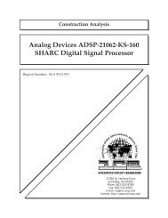
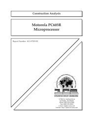
Construction Analysis<br />
<strong>SGS</strong>-<strong>Thomson</strong> <strong>93C46CB1</strong><br />
<strong>1K</strong> <strong>EEPROM</strong><br />
Report Number: SCA 9612-519<br />
Serving the Global Semiconductor Industry Since 1964<br />
15022 N. 75th Street<br />
Scottsdale, AZ 85260-2476<br />
Phone: 602-998-9780<br />
Fax: 602-948-1925<br />
e-mail: ice@primenet.com<br />
Internet: http://www.ice-corp.com/ice<br />
®
INDEX TO TEXT<br />
TITLE PAGE<br />
INTRODUCTION 1<br />
MAJOR FINDINGS 1<br />
TECHNOLOGY DESCRIPTION<br />
Assembly 2<br />
Die Process 2 - 3<br />
ANALYSIS RESULTS I<br />
Assembly 4<br />
ANALYSIS RESULTS II<br />
Die Process and Design 5 - 6<br />
ANALYSIS PROCEDURE 7<br />
TABLES<br />
Overall Quality Evaluation 8<br />
Package Markings 9<br />
Wirebond Strength 9<br />
Die Material Analysis 9<br />
Horizontal Dimensions 10<br />
Vertical Dimensions 10<br />
- i -
INDEX TO FIGURES<br />
PACKAGING AND ASSEMBLY Figures 1 - 6<br />
DIE LAYOUT AND IDENTIFICATION Figures 7 - 8<br />
PHYSICAL DIE STRUCTURES Figures 9 - 33<br />
COLOR DRAWING OF DIE STRUCTURE Figure 20<br />
ROM MEMORY CELL Figures 21 - 24<br />
<strong>EEPROM</strong> MEMORY CELL Figures 25 - 32<br />
INPUT PROTECTION CIRCUIT Figure 33<br />
GENERAL CIRCUIT LAYOUT Figure 33<br />
- ii -
INTRODUCTION<br />
This report describes a construction analysis of the <strong>SGS</strong>-<strong>Thomson</strong> <strong>93C46CB1</strong> <strong>1K</strong> <strong>EEPROM</strong>.<br />
Four devices packaged in 8-pin Plastic Dual In-line Packages (PDIPs) were received for the<br />
analysis. Date codes were not identifiable (possibly 9618).<br />
Questionable Items: 1 None.<br />
Special Features:<br />
MAJOR FINDINGS<br />
• Twin-well CMOS process with single poly and tunnel oxide windows.<br />
1 <strong>The</strong>se items present possible quality or reliability concerns. <strong>The</strong>y should be discussed<br />
with the manufacturer to determine their possible impact on the intended application.<br />
- 1 -
Assembly:<br />
TECHNOLOGY DESCRIPTION<br />
• Devices were packaged in 8-pin Plastic Dual In-line Packages (PDIPs).<br />
• <strong>The</strong> dice were mounted to the paddles using a silver-filled polyimide die attach.<br />
• Die separation was by sawing.<br />
• Wirebonding was by the thermosonic ball bond method using 1.1 mil O.D. gold<br />
wire.<br />
• All pins were connected. Lead-locking provisions (anchors) at all pins.<br />
Die Process :<br />
• Devices were fabricated using a selective oxidation, twin-well CMOS process in a P<br />
substrate. No epi was used.<br />
• No die coat was present.<br />
• Passivation consisted of a layer of oxy-nitride over a layer of silicon-dioxide.<br />
• Metallization consisted of a single layer of dry-etched aluminum and did not use a<br />
cap or barrier. Standard contacts were used (no plugs).<br />
• Pre-metal dielectric consisted of a layer of borophosphosilicate glass (BPSG) over<br />
densified oxides. <strong>The</strong> glass was reflowed following contact cuts.<br />
• A single layer of poly (no silicide) was used to form all gates on the die, the word<br />
lines and one plate of the capacitors in the <strong>EEPROM</strong> cell array. Direct poly-todiffusion<br />
(buried) contacts were not used. Definition of the poly was by a dry etch.<br />
- 2 -
TECHNOLOGY DESCRIPTION (continued)<br />
• Standard implanted N+ and P+ diffusions formed the sources/drains of the CMOS<br />
transistors. An LDD process was used with oxide sidewall spacers left in place.<br />
• Local oxide (LOCOS) isolation. A slight step was present in the oxide at the edge of<br />
the well boundaries indicating a twin-well process was used.<br />
• <strong>The</strong> memory cell consisted of a 3T, single capacitor, <strong>EEPROM</strong> design. Metal was<br />
used to form the bit lines. Poly was used to form the word/select lines, one plate of<br />
the capacitor and the tunnel-oxide device.<br />
• Two separate small MROM arrays were also present. One of these used poly mask<br />
programming, the other field oxide mask (i.e., diffusion) programming.<br />
• Redundancy fuses were not present.<br />
- 3 -
Package and Assembly:<br />
Questionable Items: 1 None.<br />
Special Features: None.<br />
General Items:<br />
ANALYSIS RESULTS I<br />
- 4 -<br />
Figures 1 - 6<br />
• Devices were packaged in 8-pin Plastic Dual In-line Packages (PDIPs).<br />
• Overall package quality: Good. No significant defects were noted on the external or<br />
internal portions of the package. No cracks or voids were noted in the plastic.<br />
• Leadframe: <strong>The</strong> leadframe was constructed of copper.<br />
• Die dicing: Die separation was by sawing of normal quality. No large cracks or<br />
chips were present.<br />
• Die attach: A silver-filled polyimide of normal quality was used to attach the die to<br />
the paddle.<br />
• Wirebonding was by the thermosonic ball bond method using 1.1 mil O.D. gold<br />
wire. Bonds were well formed and placement was good. Wirepull strengths were<br />
normal with no bond lifts (see page 10).<br />
1 <strong>The</strong>se items present possible quality or reliability concerns. <strong>The</strong>y should be discussed<br />
with the manufacturer to determine their possible impact on the intended application.
Die Process:<br />
Questionable Items: 1 None.<br />
Special Features:<br />
• Single poly, tunnel oxide windows.<br />
General Items:<br />
ANALYSIS RESULTS II<br />
- 5 -<br />
Figures 7 - 33<br />
• Fabrication process: Devices were fabricated using a selective oxidation, twin-well<br />
CMOS process in a P substrate. No epi was used.<br />
• Process implementation: Die layout was clean and efficient. Alignment was good at<br />
all levels. No damage or contamination was found.<br />
• Die coat: No die coat was present.<br />
• Overlay passivation: A layer of oxy-nitride over a layer of silicon-dioxide. Overlay<br />
integrity test indicated defect-free passivation. Edge seal was good as it extended<br />
into the scribe lane to seal the metallization.<br />
• Metallization: A single layer of metal consisting of aluminum. No cap or barrier<br />
metals were used.<br />
• Metal patterning: <strong>The</strong> metal layer was patterned by a dry etch of normal quality. All<br />
contacts were completely surrounded by aluminum.<br />
• Metal defects: No voiding, notching, or neckdown was noted in the metal layer.<br />
No silicon nodules were noted following the removal of the aluminum layer.<br />
1 <strong>The</strong>se items present possible quality or reliability concerns. <strong>The</strong>y should be discussed<br />
with the manufacturer to determine their possible impact on the intended application.
ANALYSIS RESULTS II (continued)<br />
• Metal step coverage: Worst case aluminum thinning was 65 percent at contact<br />
edges. Typical aluminum thinning was 50 percent. MIL-STD allows up to 70<br />
percent metal thinning for contacts of this size.<br />
• Pre-metal dielectric: A layer of borophosphosilicate glass ( BPSG) over densified<br />
oxides was used under the metal. Reflow was performed following contact cuts.<br />
No problems were found.<br />
• Contact defects: None. Alignment was good and no significant over-etching of the<br />
contacts was noted.<br />
• Polysilicon: A single layer of poly (no silicide) was used to form all gates, word lines,<br />
and one plate of the capacitors in the <strong>EEPROM</strong> cell array. Direct poly-to-diffusion<br />
(buried) contacts were not used. Definition was by a dry etch of normal quality.<br />
• Diffusions: Standard implanted N+ and P+ diffusions formed the sources/drains of<br />
the CMOS transistors. An LDD process was used with oxide sidewall spacers left<br />
in place. No silicide was present over diffusions.<br />
• Local oxide (LOCOS) isolation was used. No problems were noted. <strong>The</strong> slight step<br />
present in the oxide at the well boundary indicates a twin-well process was<br />
employed. <strong>The</strong> P-well could not be delineated in cross section.<br />
• ROM arrays: Two different MROM array types were present on the device. Both<br />
were located at one end of the die. One array was programmed at the poly level (see<br />
Figures 21 and 22) and the other array was programmed at the diffusion level (see<br />
Figures 23 and 24).<br />
• <strong>EEPROM</strong>: <strong>The</strong> <strong>EEPROM</strong> memory cells used three transistor, single capacitor<br />
<strong>EEPROM</strong> design. Metal was used to form the bit lines. Poly was used to form the<br />
word/select lines, one plate of the capacitor, and the tunnel oxide device. Cell pitch<br />
was 7.8 x 18.4 microns.<br />
• Redundancy fuses were not present on the die.<br />
- 6 -
PROCEDURE<br />
<strong>The</strong> devices were subjected to the following analysis procedures:<br />
External inspection<br />
X-ray<br />
Decapsulate<br />
Internal optical inspection<br />
SEM of passivation and assembly features<br />
Passivation integrity test<br />
Wirepull test<br />
Passivation removal<br />
SEM inspection of metal<br />
Metal removal<br />
Delayer to silicon and inspect poly/die surface<br />
Die sectioning (90° for SEM) *<br />
Die material analysis<br />
Measure horizontal dimensions<br />
Measure vertical dimensions<br />
* Delineation of cross-sections is by silicon etch unless otherwise indicated.<br />
- 7 -
OVERALL QUALITY EVALUATION: Overall Rating: Good<br />
DETAIL OF EVALUATION<br />
Package integrity N<br />
Package markings N<br />
Die placement N<br />
Wirebond placement N<br />
Wire spacing N<br />
Wirebond quality N<br />
Die attach quality N<br />
Dicing quality N<br />
Die attach method Silver-filled polyimide<br />
Dicing method Sawn<br />
Wirebond method <strong>The</strong>rmosonic ball bonds using 1.1 mil gold wire.<br />
Die surface integrity:<br />
Toolmarks (absence) G<br />
Particles (absence) G<br />
Contamination (absence) G<br />
Process defects (absence) G<br />
General workmanship G<br />
Passivation integrity G<br />
Metal definition N<br />
Metal integrity N<br />
Contact coverage G<br />
Contact registration G<br />
G = Good, P = Poor, N = Normal, NP = Normal/Poor<br />
- 8 -
Wire material: 1.1 mil O.D. gold<br />
Die pad material: aluminum<br />
Sample # 1<br />
# of wires pulled: 8<br />
Bond lifts: 0<br />
Force to break - high: 9.5g<br />
- low: 4.5g<br />
- avg.: 7.5g<br />
- std. dev.: 1.6<br />
PACKAGE MARKINGS (TOP)<br />
<strong>93C46CB1</strong><br />
91E618<br />
(LOGO ) MAL<br />
(BOTTOM)<br />
NONE<br />
WIREBOND STRENGTH<br />
DIE MATERIAL ANALYSIS<br />
Overlay passivation: A layer of oxy-nitride over a layer of silicon-<br />
dioxide.<br />
Metallization: * Aluminum (Al).<br />
Pre-metal dielectric: A layer of borophosphosilicate glass (BPSG)<br />
containing 3.4 wt. % phosphorus and 3.6 wt. %<br />
boron over various densified oxides.<br />
∗ <strong>The</strong>re is no known method for determining the exact amount of silicon or copper in the aluminum<br />
of a finished die.<br />
- 9 -
HORIZONTAL DIMENSIONS<br />
Die size: 1.4 x 1.8 mm (56 x 72 mils)<br />
Die area: 2.6 mm2 (4,032 mils2 )<br />
Min pad size: 0.12 x 0.12 mm (4.7 x 4.7 mils)<br />
Min pad window: 0.11 x 0.11 mm (4.3 x 4.3 mils)<br />
Min pad space: 0.08 mm (3.1 mils)<br />
Min metal width: 1.7 micron<br />
Min metal space: 1.6 micron<br />
Min metal pitch: 3.3 microns<br />
Min contact: 1.1 micron<br />
Min poly width: 1.2 micron<br />
Min poly space: 1.4 micron<br />
Min gate length - (N-channel): * 1.2 micron<br />
- (P-channel): 1.3 micron<br />
Cell size: 143 microns2 Cell pitch: 7.8 x 18.4 microns<br />
VERTICAL DIMENSIONS<br />
Die thickness: 0.5 mm (19.5 mils)<br />
Layers:<br />
Passivation 2: 0.6 micron<br />
Passivation 1: 0.4 micron<br />
Metal: 0.85 micron<br />
Pre-metal dielectric: 0.4 micron (avg.)<br />
Oxide on poly: 0.25 micron<br />
Poly: 0.4 micron<br />
Local oxide: 0.6 micron<br />
N+ S/D: 0.3 micron<br />
P + S/D: 0.5 micron<br />
N-well: 3 microns<br />
P-well: Could not delineate<br />
* Physical gate length<br />
- 10 -
<strong>SGS</strong>-<strong>Thomson</strong> <strong>93C46CB1</strong><br />
CS<br />
CLK<br />
D.I.<br />
D.O.<br />
1<br />
2<br />
3<br />
4<br />
Integrated Circuit Engineering Corporation<br />
Figure 1. Package photograph and pinout diagram of the <strong>SGS</strong>-<strong>Thomson</strong> <strong>93C46CB1</strong><br />
<strong>1K</strong>bit <strong>EEPROM</strong>. Mag. 7.5x.<br />
8<br />
7<br />
6<br />
5<br />
D.U. = DON'T USE<br />
VCC<br />
D.U.<br />
ORG<br />
VSS
<strong>SGS</strong>-<strong>Thomson</strong> <strong>93C46CB1</strong><br />
PIN 1<br />
top view<br />
side view<br />
Figure 2. X-ray views of the package. Mag. 8x.<br />
Integrated Circuit Engineering Corporation
<strong>SGS</strong>-<strong>Thomson</strong> <strong>93C46CB1</strong><br />
Figure 3. Perspective SEM view of a typical ball bond. Mag. 600x. 60°.<br />
PASSIVATION<br />
METAL<br />
Au<br />
LOCOS<br />
Au BALL BOND<br />
Figure 4. SEM section views of the bond pad.<br />
Integrated Circuit Engineering Corporation<br />
Mag. 3000x<br />
Mag. 10,000x
<strong>SGS</strong>-<strong>Thomson</strong> <strong>93C46CB1</strong><br />
Mag. 150x<br />
Mag. 1300x<br />
DIE<br />
EDGE OF PASSIVATION<br />
Figure 5. SEM views of die corner and edge seal. 60°.<br />
Integrated Circuit Engineering Corporation
<strong>SGS</strong>-<strong>Thomson</strong> <strong>93C46CB1</strong><br />
METAL<br />
LOCOS<br />
SCRIBE LANE<br />
123<br />
PASSIVATION<br />
METAL<br />
PASSIVATION<br />
DIE EDGE<br />
Figure 6. SEM views of the edge seal.<br />
Integrated Circuit Engineering Corporation<br />
Mag. 1600x<br />
Mag. 5000x<br />
Mag. 13,000x
<strong>SGS</strong>-<strong>Thomson</strong> <strong>93C46CB1</strong><br />
PIN 1<br />
Integrated Circuit Engineering Corporation<br />
Figure 7. Whole die photograph of the <strong>SGS</strong>-<strong>Thomson</strong> <strong>93C46CB1</strong> <strong>EEPROM</strong>. Mag. 120x.
<strong>SGS</strong>-<strong>Thomson</strong> <strong>93C46CB1</strong><br />
Figure 8. Identification markings from the die surface. Mag. 400x.<br />
Integrated Circuit Engineering Corporation
<strong>SGS</strong>-<strong>Thomson</strong> <strong>93C46CB1</strong><br />
LOCAL OXIDE<br />
PASSIVATION<br />
METAL<br />
PASSIVATION<br />
P+<br />
POLY GATE<br />
Mag. 6200x<br />
Mag. 13,000x<br />
POLY<br />
LOCAL OXIDE<br />
Figure 9. SEM section views illustrating general device structure.<br />
Integrated Circuit Engineering Corporation<br />
METAL
<strong>SGS</strong>-<strong>Thomson</strong> <strong>93C46CB1</strong><br />
Mag. 2500x<br />
Mag. 10,000x<br />
Figure 10. SEM views of overlay passivation coverage. 60°.<br />
Integrated Circuit Engineering Corporation
<strong>SGS</strong>-<strong>Thomson</strong> <strong>93C46CB1</strong><br />
DIE<br />
Mag. 13,000x<br />
PASSIVATION 2<br />
PASSIVATION 1<br />
METAL<br />
PRE-METAL GLASS<br />
Mag. 26,000x<br />
PASSIVATION<br />
METAL<br />
Figure 11. SEM section views of metal line profiles.<br />
Integrated Circuit Engineering Corporation
<strong>SGS</strong>-<strong>Thomson</strong> <strong>93C46CB1</strong><br />
METAL<br />
METAL<br />
METAL<br />
CONTACTS<br />
Figure 12. Topological SEM views illustrating metal patterning. 0°.<br />
Integrated Circuit Engineering Corporation<br />
Mag. 1600x<br />
Mag. 2500x<br />
Mag. 3300x
<strong>SGS</strong>-<strong>Thomson</strong> <strong>93C46CB1</strong><br />
METAL<br />
METAL<br />
METAL<br />
POLY<br />
Figure 13. Perspective SEM views illustrating metal coverage. 60°.<br />
Integrated Circuit Engineering Corporation<br />
Mag. 2500x<br />
Mag. 4000x<br />
Mag. 10,000x
<strong>SGS</strong>-<strong>Thomson</strong> <strong>93C46CB1</strong><br />
PRE-METAL<br />
GLASS<br />
PASSIVATION<br />
METAL<br />
METAL<br />
METAL<br />
P+<br />
POLY<br />
N+<br />
LOCAL OXIDE<br />
DENSIFIED<br />
OXIDE<br />
PASSIVATION<br />
Figure 14. SEM section views of metal contacts.<br />
Integrated Circuit Engineering Corporation<br />
POLY GATE<br />
POLY GATE<br />
metal-to-N+,<br />
Mag. 20,000x<br />
metal-to-P+,<br />
Mag. 20,000x<br />
metal-to-poly,<br />
Mag. 26,000x
<strong>SGS</strong>-<strong>Thomson</strong> <strong>93C46CB1</strong><br />
POLY<br />
METAL<br />
POLY<br />
METAL<br />
Figure 14a. Perspective SEM views of circular devices. 60°.<br />
Integrated Circuit Engineering Corporation<br />
metal,<br />
Mag. 1900x<br />
metal,<br />
Mag. 2500x<br />
unlayered,<br />
Mag. 2500x
<strong>SGS</strong>-<strong>Thomson</strong> <strong>93C46CB1</strong><br />
N+<br />
POLY<br />
POLY<br />
POLY<br />
Figure 15. Topological SEM views illustrating poly patterning. 0°.<br />
P+<br />
Integrated Circuit Engineering Corporation<br />
Mag. 1600x<br />
Mag. 3300x<br />
Mag. 5000x
<strong>SGS</strong>-<strong>Thomson</strong> <strong>93C46CB1</strong><br />
POLY<br />
DIFFUSION<br />
Mag. 2600x<br />
Mag. 13,000x<br />
Figure 16. SEM views illustrating poly coverage. 60°.<br />
Integrated Circuit Engineering Corporation
<strong>SGS</strong>-<strong>Thomson</strong> <strong>93C46CB1</strong><br />
SIDEWALL<br />
SPACER<br />
PASSIVATION<br />
PASSIVATION<br />
PRE-METAL GLASS<br />
GATE OXIDE<br />
POLY GATE<br />
PRE-METAL GLASS<br />
POLY GATE<br />
GATE OXIDE<br />
POLY GATE<br />
N+ S/D<br />
METAL<br />
P+ S/D<br />
METAL<br />
PRE-METAL GLASS<br />
Integrated Circuit Engineering Corporation<br />
N-channel<br />
P-channel<br />
glass-etch<br />
Figure 17. SEM section views illustrating typical gates. Mag. 26,000x.
<strong>SGS</strong>-<strong>Thomson</strong> <strong>93C46CB1</strong><br />
GATE OXIDE<br />
Integrated Circuit Engineering Corporation<br />
Figure 18. SEM section view of a local oxide birdsbeak profile. Mag. 26,000x.<br />
METAL<br />
LOCAL OXIDE<br />
STEP AT WELL<br />
BOUNDARY<br />
METAL<br />
PRE-METAL GLASS<br />
POLY<br />
POLY<br />
N-WELL<br />
P SUBSTRATE<br />
LOCAL OXIDE<br />
Figure 19. Optical and SEM views illustrating well structure.<br />
Mag. 20,000x<br />
Mag. 1600x
P-WELL<br />
POLY GATE<br />
SIDEWALL SPACER<br />
N+ S/D<br />
PRE-METAL DIELECTRIC<br />
LOCAL OXIDE<br />
,,,,,,,,<br />
,,,,,,,,<br />
P SUBSTRATE<br />
METAL<br />
N-WELL<br />
Orange = Nitride, Blue = Metal, Yellow = Oxide, Green = Poly,<br />
Red = Diffusion, and Gray = Substrate<br />
Figure 20. Color cross section drawing illustrating device structure.<br />
PASSIVATION 2<br />
PASSIVATION 1<br />
P+ S/D<br />
<strong>SGS</strong>-<strong>Thomson</strong> <strong>93C46CB1</strong><br />
Integrated Circuit Engineering Corporation
<strong>SGS</strong>-<strong>Thomson</strong> <strong>93C46CB1</strong><br />
DIFFUSION<br />
POLY GATES<br />
POLY GATE<br />
Integrated Circuit Engineering Corporation<br />
metal,<br />
Mag. 1600x<br />
poly,<br />
Mag. 1600x<br />
poly,<br />
Mag. 3300x<br />
Figure 21. Topological views of an MROM array on the <strong>93C46CB1</strong>. 0°.
<strong>SGS</strong>-<strong>Thomson</strong> <strong>93C46CB1</strong><br />
POLY GATE<br />
DIFFUSION<br />
Figure 22. Perspective SEM views of the MROM array. 60°.<br />
Integrated Circuit Engineering Corporation<br />
metal,<br />
Mag. 5000x<br />
poly,<br />
Mag. 2600x<br />
poly,<br />
Mag. 5000x
<strong>SGS</strong>-<strong>Thomson</strong> <strong>93C46CB1</strong><br />
METAL<br />
POLY GATE<br />
POLY WORD<br />
LINES<br />
Integrated Circuit Engineering Corporation<br />
POLY<br />
(ON LOCAL OXIDE)<br />
metal,<br />
Mag. 1600x<br />
poly,<br />
Mag. 1600x<br />
poly,<br />
Mag. 6500x<br />
Figure 23. Topological SEM views of an additional MROM array on the <strong>93C46CB1</strong>. 0°.
<strong>SGS</strong>-<strong>Thomson</strong> <strong>93C46CB1</strong><br />
metal<br />
DIFFUSION<br />
poly<br />
Figure 24. Perspective SEM views of the MROM array. Mag. 2600x, 60°.<br />
Integrated Circuit Engineering Corporation<br />
POLY<br />
(ON LOCAL OXIDE)<br />
POLY GATE
<strong>SGS</strong>-<strong>Thomson</strong> <strong>93C46CB1</strong><br />
BIT LINE<br />
BIT LINE<br />
metal<br />
poly<br />
Integrated Circuit Engineering Corporation<br />
POLY WORD LINES<br />
CAPACITORS<br />
Figure 25. Topological SEM views of the <strong>EEPROM</strong> array. Mag. 1600x, 0°.
<strong>SGS</strong>-<strong>Thomson</strong> <strong>93C46CB1</strong><br />
BIT LINE<br />
BIT LINE<br />
metal<br />
poly<br />
POLY WORD<br />
LINES<br />
Integrated Circuit Engineering Corporation<br />
Figure 26. Perspective SEM views of the <strong>EEPROM</strong> array. Mag. 2000x, 60°.
<strong>SGS</strong>-<strong>Thomson</strong> <strong>93C46CB1</strong><br />
BIT LINE<br />
BIT LINE<br />
CAPACITOR<br />
CAPACITOR<br />
CAPACITOR<br />
POLY WORD LINE<br />
TUNNEL OXIDE<br />
DEVICE<br />
POLY<br />
Figure 27. Detail views of the <strong>EEPROM</strong> array. 60°.<br />
Integrated Circuit Engineering Corporation<br />
metal,<br />
Mag. 5000x<br />
poly,<br />
Mag. 5000x<br />
poly,<br />
Mag. 10,000x
<strong>SGS</strong>-<strong>Thomson</strong> <strong>93C46CB1</strong><br />
BIT A<br />
BIT B<br />
C<br />
TUNNEL<br />
OXIDE DEVICE<br />
BIT LINE<br />
WORD<br />
C<br />
3<br />
1<br />
3<br />
2<br />
2<br />
1<br />
BIT B<br />
BIT A<br />
SHARED WITH<br />
ADJACENT CELL<br />
TO ADJACENT CELL<br />
TO ADJACENT CELL<br />
SHARED WITH<br />
ADJACENT CELL<br />
Integrated Circuit Engineering Corporation<br />
metal<br />
poly<br />
Figure 28. Topological SEM views of an <strong>EEPROM</strong> cell along with the schematic.<br />
Mag. 3300x, 0°.
<strong>SGS</strong>-<strong>Thomson</strong> <strong>93C46CB1</strong><br />
POLY GATE<br />
PASSIVATION 2<br />
PASSIVATION 1<br />
N+<br />
PASSIVATION 2<br />
PASSIVATION 1<br />
N+<br />
METAL BIT LINE<br />
GATE OXIDE<br />
POLY GATE<br />
METAL BIT LINE<br />
GATE OXIDE<br />
METAL BIT LINE<br />
N+ S/D<br />
Integrated Circuit Engineering Corporation<br />
Mag. 11,000x<br />
Mag. 26,000x<br />
Mag. 26,000x<br />
Figure 29. SEM section views of an <strong>EEPROM</strong> cell illustrating bit line contact<br />
and select gate.
<strong>SGS</strong>-<strong>Thomson</strong> <strong>93C46CB1</strong><br />
PASSIVATION<br />
POLY GATE<br />
N+ (GND)<br />
GATE OXIDE<br />
PASSIVATION<br />
POLY<br />
POLY<br />
CAPACITOR<br />
POLY<br />
CAPACITOR<br />
N+ (GND)<br />
Figure 30. Detail SEM views of the <strong>EEPROM</strong> cell structure.<br />
Integrated Circuit Engineering Corporation<br />
LOCAL<br />
OXIDE<br />
Mag. 3300x<br />
Mag. 6500x<br />
Mag. 26,000x
<strong>SGS</strong>-<strong>Thomson</strong> <strong>93C46CB1</strong><br />
POLY WORD LINE<br />
PASSIVATION<br />
N+<br />
METAL BIT<br />
LINES<br />
Mag. 8000x<br />
METAL BIT LINE<br />
CONTACTS<br />
Mag. 9000x<br />
LOCAL OXIDE<br />
Integrated Circuit Engineering Corporation<br />
Figure 31. SEM section views of <strong>EEPROM</strong> cells (perpendicular to bit lines).
<strong>SGS</strong>-<strong>Thomson</strong> <strong>93C46CB1</strong><br />
TUNNEL OXIDE<br />
DEVICE<br />
PASSIVATION<br />
METAL<br />
POLY GATE (3)<br />
POLY<br />
TUNNEL OXIDE<br />
Mag. 6500x<br />
Mag. 13,000x<br />
METAL BIT LINES<br />
POLY<br />
Integrated Circuit Engineering Corporation<br />
GATE OXIDE<br />
Figure 32. SEM section views of <strong>EEPROM</strong> cells (perpendicular to bit lines).<br />
N+
<strong>SGS</strong>-<strong>Thomson</strong> <strong>93C46CB1</strong><br />
Integrated Circuit Engineering Corporation<br />
Mag. 160x<br />
Mag. 400x<br />
Mag. 800x<br />
Figure 33. Optical views of input protection and typical circuit layout.