Torsion
Torsion
Torsion

You also want an ePaper? Increase the reach of your titles
YUMPU automatically turns print PDFs into web optimized ePapers that Google loves.
134 CHAPTER 5. TORSION<br />
were assumed to remain valid for a bar of arbitrary cross-section, the displacement field, eqs. (5.4) and (5.3),<br />
and the corresponding strain field, eqs. (5.5) to (5.7), would also describe the kinematics of bars with arbitrary<br />
sections. The only non-vanishing stress component would be the circumferential shearing stress given by<br />
eq. (5.12).<br />
Unfortunately, this assumption can lead to grossly erroneous results because it implies a solution that<br />
violates the equilibrium equations of the problem at the edge of the section. Consider, for instance, the torsion<br />
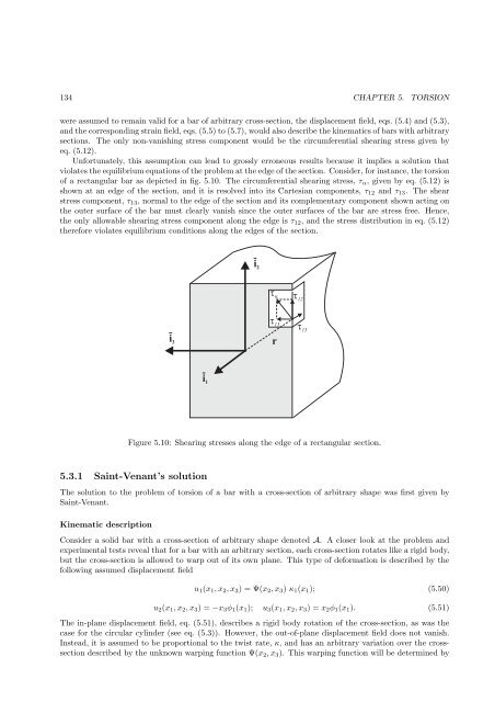
of a rectangular bar as depicted in fig. 5.10. The circumferential shearing stress, τα, given by eq. (5.12) is<br />
shown at an edge of the section, and it is resolved into its Cartesian components, τ12 and τ13. The shear<br />
stress component, τ13, normal to the edge of the section and its complementary component shown acting on<br />
the outer surface of the bar must clearly vanish since the outer surfaces of the bar are stress free. Hence,<br />
the only allowable shearing stress component along the edge is τ12, and the stress distribution in eq. (5.12)<br />
therefore violates equilibrium conditions along the edges of the section.<br />
i 3<br />
i 1<br />
i 2<br />
Figure 5.10: Shearing stresses along the edge of a rectangular section.<br />
5.3.1 Saint-Venant’s solution<br />
The solution to the problem of torsion of a bar with a cross-section of arbitrary shape was first given by<br />
Saint-Venant.<br />
Kinematic description<br />
Consider a solid bar with a cross-section of arbitrary shape denoted A. A closer look at the problem and<br />
experimental tests reveal that for a bar with an arbitrary section, each cross-section rotates like a rigid body,<br />
but the cross-section is allowed to warp out of its own plane. This type of deformation is described by the<br />
following assumed displacement field<br />
<br />
13<br />
r<br />
12<br />
13<br />
u1(x1, x2, x3) = Ψ(x2, x3) κ1(x1); (5.50)<br />
u2(x1, x2, x3) = −x3φ1(x1); u3(x1, x2, x3) = x2φ1(x1). (5.51)<br />
The in-plane displacement field, eq. (5.51), describes a rigid body rotation of the cross-section, as was the<br />
case for the circular cylinder (see eq. (5.3)). However, the out-of-plane displacement field does not vanish.<br />
Instead, it is assumed to be proportional to the twist rate, κ, and has an arbitrary variation over the crosssection<br />
described by the unknown warping function Ψ(x2, x3). This warping function will be determined by