Torsion
Torsion
Torsion

Create successful ePaper yourself
Turn your PDF publications into a flip-book with our unique Google optimized e-Paper software.
124 CHAPTER 5. TORSION<br />
Q 1<br />
i 3<br />
R<br />
i 2<br />
i 3<br />
Circular<br />
cylinder<br />
i 2<br />
R i<br />
R o<br />
i 3<br />
Circular<br />
annulus<br />
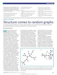
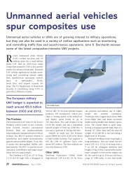
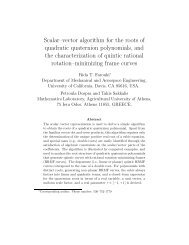
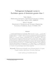
Figure 5.1: Circular cylinder with end torques.<br />
written as the projection of this displacement along directions ī2 and ī3, respectively,<br />
u2(x1, r, α) = −rφ1(x1) sin α; u3(x1, r, α) = rφ1(x1) cos α. (5.1)<br />
Since the cross-section does not deform out of its own plane, the axial displacement field must vanish,<br />
i.e. u1(x1, x2, x3) = 0. Finally, the transformation from polar to Cartesian coordinates is<br />
i 1<br />
i 2<br />
Q1<br />
x2 = r cos α; x3 = r sin α. (5.2)<br />
The complete displacement field describing the torsion of circular cylinders expressed in Cartesian coordinates<br />
can now be written by substituting eq. (5.2) in (5.1) to yield<br />
and<br />
u2(x1, x2, x3) = −x3φ1(x1); u3(x1, x2, x3) = x2φ1(x1) (5.3)<br />
u1(x1, x2, x3) = 0. (5.4)<br />
The corresponding strain field is readily obtained using the strain-displacement equations as:<br />
ε1 = ∂u1<br />
= 0; (5.5)<br />
∂x1<br />
ε2 = ∂u2<br />
= 0; ε3 =<br />
∂x2<br />
∂u3<br />
= 0; γ23 =<br />
∂x3<br />
∂u2<br />
+<br />
∂x3<br />
∂u3<br />
= 0; (5.6)<br />
∂x2<br />
γ12 = ∂u1<br />
+<br />
∂x2<br />
∂u2<br />
∂x1<br />
= −x3 κ1(x1); γ13 = ∂u1<br />
+<br />
∂x3<br />
∂u3<br />
∂x1<br />
= x2 κ1(x1), (5.7)<br />
where the sectional twist rate is defined as<br />
κ1(x1) = dφ1<br />
. (5.8)<br />
dx1<br />
The section twist rate, κ1, measures the deformation of the circular cylinder. The twist angle, φ1, simply<br />
measures the rotation of any section with respect to a reference. Note that a constant twist angle implies a<br />
rigid body rotation of the cylinder about its axis, but no deformation.