Torsion
Torsion
Torsion

You also want an ePaper? Increase the reach of your titles
YUMPU automatically turns print PDFs into web optimized ePapers that Google loves.
148 CHAPTER 5. TORSION<br />
b<br />
i 3<br />
b >>t<br />
i 2<br />
max<br />
(a) (b)<br />
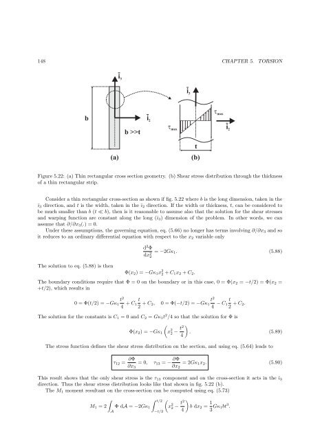
Figure 5.22: (a) Thin rectangular cross section geometry. (b) Shear stress distribution through the thickness<br />
of a thin rectangular strip.<br />
Consider a thin rectangular cross-section as shown if fig. 5.22 where b is the long dimension, taken in the<br />
ī3 direction, and t is the width, taken in the ī2 direction. If the width or thickness, t, can be considered to<br />
be much smaller than b (t ≪ b), then is it reasonable to assume also that the solution for the shear stresses<br />
and warping function are constant along the long (ī3) dimension of the problem. In other words, we can<br />
assume that ∂/∂x3(.) = 0.<br />
Under these assumptions, the governing equation, eq. (5.66) no longer has terms involving ∂/∂x3 and so<br />
it reduces to an ordinary differential equation with respect to the x2 variable only<br />
The solution to eq. (5.88) is then<br />
d 2 Φ<br />
dx 2 2<br />
i 3<br />
t<br />
max<br />
= −2Gκ1. (5.88)<br />
Φ(x2) = −Gκ1x 2 2 + C1x2 + C2.<br />
The boundary conditions require that Φ = 0 on the boundary or in this case, 0 = Φ(x2 = −t/2) = Φ(x2 =<br />
+t/2), which results in<br />
t<br />
0 = Φ(t/2) = −Gκ1<br />
2<br />
4<br />
t<br />
+ C1<br />
2 + C2,<br />
t<br />
0 = Φ(−t/2) = −Gκ1<br />
2<br />
4<br />
i 2<br />
t<br />
− C1 + C2.<br />
2<br />
The solution for the constants is C1 = 0 and C2 = Gκ1t 2 /4 so that the solution for Φ is<br />
Φ(x2) = −Gκ1<br />
<br />
x 2 2 − t2<br />
<br />
. (5.89)<br />
4<br />
The stress function defines the shear stress distribution on the section, and using eq. (5.64) leads to<br />
τ12 = ∂Φ<br />
= 0, τ13 = −<br />
∂x3<br />
∂Φ<br />
= 2Gκ1x2. (5.90)<br />
∂x2<br />
This result shows that the only shear stress is the τ13 component and on the cross-section it acts in the ī3<br />
direction. Thus the shear stress distribution looks like that shown in fig. 5.22 (b).<br />
The M1 moment resultant on the cross-section can be computed using eq. (5.73)<br />
<br />
t/2 <br />
M1 = 2 Φ dA = −2Gκ1 x<br />
A<br />
−t/2<br />
2 2 − t2<br />
<br />
b dx2 =<br />
4<br />
1<br />
3 Gκ1bt 3 .