- Page 1:
The computation of turbulent natura
- Page 4 and 5:
3.2 Mean Flow Equations and their s
- Page 6 and 7:
7.2.6 FFT analysis . . . . . . . .
- Page 8 and 9:
List of Figures 2.1 Comparison of e
- Page 10 and 11:
6.15 Temperature and stream lines w
- Page 12 and 13:
6.45 Temperature fluctuations withi
- Page 14 and 15:
7.9 rms velocity fluctuations compa
- Page 16 and 17:
7.43 Temperature contours within x-
- Page 18 and 19:
7.82 Mean velocity distributions re
- Page 20 and 21:
7.119Time-averaged rms velocity flu
- Page 22 and 23:
8.23 Contour plots of V, W andk at
- Page 24 and 25:
8.49 Contour plots of V, W andk at
- Page 26 and 27:
For the inclined tall cavities, in
- Page 28 and 29:
Declaration No portion of the work
- Page 30 and 31:
Acknowledgements I would like to ex
- Page 32 and 33:
Nomenclature Acronyms AWF Analytica
- Page 34 and 35:
λ Thermal conductivity µ Molecula
- Page 36 and 37:
cl Equilibrium length scale constan
- Page 38 and 39:
yd Thickness of the dissipative lay
- Page 40 and 41:
Chapter 1 Introduction In this rese
- Page 42 and 43:
41 need fine numerical resolution n
- Page 44 and 45:
43 nonlinear discretization methods
- Page 46 and 47:
45 the only way to achieve computat
- Page 48 and 49:
47 elaborate expressions for modell
- Page 50 and 51:
Chapter 2 Literature Review In this
- Page 52 and 53:
51 local Nusselt number occurs in t
- Page 54 and 55:
53 Cavities and Enclosures Kirkpatr
- Page 56 and 57:
55 boundary conditions which avoid
- Page 58 and 59:
57 of cold wall. They showed that t
- Page 60 and 61:
59 their predictions and their expe
- Page 62 and 63:
61 and the fluid near the vertical
- Page 64 and 65:
63 term in the ε equation performe
- Page 66 and 67:
65 space and time. Then the full al
- Page 68 and 69:
67 with heated vertical walls. They
- Page 70 and 71:
69 horizontal axis. This tall cavit
- Page 72 and 73:
71 • Large eddy simulation (LES):
- Page 74 and 75:
73 ρuiuj = 2 3 ρkδij ∂Ui −
- Page 76 and 77:
75 3.3.3 Low-Reynolds Number k-ε m
- Page 78 and 79:
77 diffusivity model is rather simp
- Page 80 and 81:
79 ∂(ρεθ) ∂t + ∂(ρUjεθ)
- Page 82 and 83:
81 stresses can be derived from the
- Page 84 and 85:
83 One option is to derive and solv
- Page 86 and 87:
85 εθ = 2α ∂θ Basic Different
- Page 88 and 89:
87 c1 c2 c3 c1w c2w 1.8 0.6 0.5 0.5
- Page 90 and 91:
89 are defined as: A = 1− 9 8 (A2
- Page 92 and 93:
91 2/3εδij. At moderate Reynolds
- Page 94 and 95:
93 Figure 4.1 - A low-Reynolds-numb
- Page 96 and 97:
95 energy over the near-wall contro
- Page 98 and 99:
97 wall heat flux can be obtained f
- Page 100 and 101:
99 values. • The convection terms
- Page 102 and 103:
101 is: Θ1 = Prυ µυ + Prυbµ
- Page 104 and 105:
103 where Θwall = Θn − Prυ + P
- Page 106 and 107:
105 C = µ2 υ ρ 2 υ kP ∂(ρUU
- Page 108 and 109:
107 +A1y ∗ + by∗2 2 + bµy ∗
- Page 110 and 111:
109 where B2 = y ∗ C1 υ 2 y∗
- Page 112 and 113:
111 where ∂U2 ∂y∗ = C2y∗ +A
- Page 114 and 115:
113 and the other option is to calc
- Page 116 and 117:
115 explained. It might be noted th
- Page 118 and 119:
117 near-wall treatments available
- Page 120 and 121:
119 N n W w P e E s S Figure 5.2 -
- Page 122 and 123:
121 φw = φW + φP −φW 2 − φ
- Page 124 and 125:
123 The schemes are SIMPLE (“Semi
- Page 126 and 127:
125 Pe = P ∗ +P ′ ′ 1 +P 2 (5
- Page 128 and 129:
127 Update P ′ from equation 5.26
- Page 130 and 131:
129 5.6 Time-dependent computations
- Page 132 and 133:
131 For the thermal boundary condit
- Page 134 and 135:
133 gx = g cos(Ψ) (5.42) gy = −g
- Page 136 and 137:
135 stable and unstable inclined ta
- Page 138 and 139:
137 variations. In these calculatio
- Page 140 and 141:
139 Rayleigh number Ra = βg∆ΘL3
- Page 142 and 143:
141 V/V 0 0.2 0 -0.2 Y=0.95 EXP 0 0
- Page 144 and 145:
143 U/V 0 0.2 0 -0.2 0 0.2 0.4 0.6
- Page 146 and 147:
145 Temperature contours Stream lin
- Page 148 and 149:
147 Temperature contours Stream lin
- Page 150 and 151:
149 Temperature contours Stream lin
- Page 152 and 153:
151 Temperature contours Stream lin
- Page 154 and 155:
153 diagrams show that the LRN k-ε
- Page 156 and 157:
155 2 k/V0 V/V 0 0.08 0.06 0.04 0.0
- Page 158 and 159:
157 2 k/V0 2 k/V0 0.03 0.02 0.01 LR
- Page 160 and 161:
159 Figure 6.26 - Mean velocity vec
- Page 162 and 163:
161 6.4.2 k-ε predictions In Figur
- Page 164 and 165:
163 In Figure 6.29, the Nusselt num
- Page 166 and 167:
165 moves down from the top of the
- Page 168 and 169:
167 v rms /V 0 v rms /V 0 v rms /V
- Page 170 and 171:
169 T T T T 1 0.8 0.6 0.4 0.2 Y=0.9
- Page 172 and 173:
171 2 uv/V0 2 uv/V0 2 uv/V0 2 uv/V0
- Page 174 and 175:
173 Nu 20 15 10 5 Cold Wall 0 0 0.2
- Page 176 and 177:
175 T T T T 1 0.8 0.6 0.4 Y=0.95 0.
- Page 178 and 179:
177 V/V 0 V/V 0 0.4 0.2 0 -0.2 -0.4
- Page 180 and 181:
179 In Figures 6.44-6.46, the rms t
- Page 182 and 183:
181 θ rms /ΔΘ θ rms /ΔΘ θ rm
- Page 184 and 185:
183 θ rms /ΔΘ θ rms /ΔΘ θ rm
- Page 186 and 187:
185 of the cavity. Figure 6.49 pres
- Page 188 and 189:
187 T T 1 0.8 0.6 0.4 0.2 Y=0.1 0 0
- Page 190 and 191:
189 θ rms /ΔΘ θ rms /ΔΘ 0.15
- Page 192 and 193:
191 Nu 20 15 10 5 Cold Wall 0 0 0.2
- Page 194 and 195:
193 Figure 6.58 - Stream traces and
- Page 196 and 197:
195 and SWF treatments is compared
- Page 198 and 199:
197 T T T T T 1 0.8 0.6 0.4 0.2 0 0
- Page 200 and 201:
199 Nu 60 40 20 LES AWF LRN SWF 0 0
- Page 202 and 203:
201 After validation of the STREAM
- Page 204 and 205:
203 V/V 0 V/V 0 0.5 0 -0.5 0.6 0.4
- Page 206 and 207:
205 T T 1 0.8 0.6 0.4 0.2 0 0 0.2 0
- Page 208 and 209:
207 v rms /V 0 v rms /V 0 0.2 0.15
- Page 210 and 211:
209 V/V 0 V/V 0 0.4 0.2 0 -0.2 -0.4
- Page 212 and 213:
211 the distance between the hot an
- Page 214 and 215:
213 1.5 Y 2 1 0.5 0 0 0.05 0.1 0.15
- Page 216 and 217:
215 7.2.4 3D time dependent simulat
- Page 218 and 219:
217 0.65 1.5 Y 0.5 Y 2 1 0.65 0.65
- Page 220 and 221:
219 0.35 0.5 0.05 0.5 0.5 0.65 0.65
- Page 222 and 223:
221 Y Y 2 1.5 1 0.5 0.35 0.5 0.5 0.
- Page 224 and 225:
223 data. The comparisons show that
- Page 226 and 227:
225 flow at this angle of inclinati
- Page 228 and 229:
227 T T T 1 0.8 0.6 0.4 0.2 T X 1 0
- Page 230 and 231:
229 U/V 0 U/V 0 U/V 0 0.4 0.2 0 -0.
- Page 232 and 233:
231 u rms /V 0 u rms /V 0 u rms /V
- Page 234 and 235:
233 u rms /V 0 u rms /V 0 0.15 0.1
- Page 236 and 237:
235 T 1 0.8 0.6 0.4 0.2 T Y=0.5 X 1
- Page 238 and 239:
237 U/V 0 0.4 0.2 0 -0.2 -0.4 Y=0.9
- Page 240 and 241:
239 u rms /V 0 0.25 0.2 0.15 0.1 0.
- Page 242 and 243:
241 Figure 7.34 - Time average vect
- Page 244 and 245:
243 Y 2 1.5 1 0.5 0.3 0.5 0.55 0.35
- Page 246 and 247:
245 PSD (T) PSD (T) PSD (T) 1 0.8 0
- Page 248 and 249:
247 PSD (T) PSD (T) PSD (T) 1 0.8 0
- Page 250 and 251:
249 PSD (T) PSD (T) PSD (T) 1 0.8 0
- Page 252 and 253:
251 the central, z=0.5, longitudina
- Page 254 and 255:
253 1.5 Y 2 1 0.5 Y 0 0 0.05 0.1 0.
- Page 256 and 257:
255 τ * =550 τ * =495 τ * =440
- Page 258 and 259:
257 Y 2 1.5 1 0.5 0.3 0.45 0.45 0.3
- Page 260 and 261:
259 not sufficiently detailed to pr
- Page 262 and 263:
261 T 1 0.8 0.6 0.4 0.2 T Y=0.5 X 1
- Page 264 and 265:
263 V/V 0 V/V 0 V/V 0 0.4 0.2 0 -0.
- Page 266 and 267:
265 V/V 0 V/V 0 0.4 0.2 0 -0.2 -0.4
- Page 268 and 269:
267 v rms /V 0 v rms /V 0 v rms /V
- Page 270 and 271:
269 v rms /V 0 v rms /V 0 0.25 0.2
- Page 272 and 273:
271 X X X 0.15 0.1 0.05 0 0 0.1 0.2
- Page 274 and 275:
273 1.5 Y 2 1 0.5 0 0 0.05 0.1 0.15
- Page 276 and 277:
275 PSD (T) PSD (T) PSD (T) 1 0.8 0
- Page 278 and 279:
277 PSD (T) PSD (T) PSD (T) 1 0.8 0
- Page 280 and 281:
279 PSD (T) PSD (T) PSD (T) 1 0.8 0
- Page 282 and 283:
281 cold wall temperatures are 53
- Page 284 and 285:
283 The reverse feature is observed
- Page 286 and 287:
285 normal components in Figures 7.
- Page 288 and 289:
287 V/V 0 V/V 0 0 -0.2 -0.4 -0.6 0
- Page 290 and 291:
289 v rms /V 0 v rms /V 0 0.15 0.1
- Page 292 and 293:
291 T T 1 0.8 0.6 0.4 0.2 Y=0.7 0 0
- Page 294 and 295:
293 V/V 0 0.8 0.6 0.4 0.2 0 -0.2 Y=
- Page 296 and 297:
295 V/V 0 V/V 0 0.6 0.4 0.2 0 -0.2
- Page 298 and 299:
297 v rms /V 0 v rms /V 0 0.15 EXP
- Page 300 and 301:
299 active sides, y-z, there are re
- Page 302 and 303:
301 V/V 0 V/V 0 0.2 0 -0.2 -0.4 -0.
- Page 304 and 305:
303 v rms /V 0 v rms /V 0 0.15 0.1
- Page 306 and 307:
305 T 1 0.8 0.6 0.4 0.2 Y=0.05 EXP
- Page 308 and 309:
307 T 1 0.8 0.6 0.4 0.2 Y=0.05 T 1
- Page 310 and 311:
309 V/V 0 0.8 0.6 0.4 0.2 0 -0.2 Y=
- Page 312 and 313:
311 v rms /V 0 0.15 0.1 0.05 EXP k-
- Page 314 and 315:
313 U/V 0 0.15 0.1 0.05 0 -0.05 -0.
- Page 316 and 317:
315 u rms /V 0 0.15 0.1 0.05 0 0 0.
- Page 318 and 319: 317 reproduce the measured temperat
- Page 320 and 321: 319 T T T 1 0.8 0.6 0.4 0.2 Y=0.9 E
- Page 322 and 323: 321 U/V 0 U/V 0 0.1 0.05 0 -0.05 -0
- Page 324 and 325: 323 u rms /V 0 u rms /V 0 0.15 0.1
- Page 326 and 327: 325 T 1 0.8 0.6 0.4 0.2 Y=0.05 T 1
- Page 328 and 329: 327 V/V 0 0.4 0.2 0 -0.2 -0.4 -0.6
- Page 330 and 331: 329 v rms /V 0 0.15 0.1 0.05 0 0 0.
- Page 332 and 333: 331 V/V 0 V/V 0 0.6 0.4 0.2 0 -0.2
- Page 334 and 335: 333 v rms /V 0 v rms /V 0 0.15 EXP
- Page 336 and 337: 335 Nu Nu X 0.15 0.1 0.05 20 15 10
- Page 338 and 339: 337 1.5 Y 2 1 0.5 0 0 0.1 0.2 0.3 Z
- Page 340 and 341: Chapter 8 Annular horizontal penetr
- Page 342 and 343: 341 8.2 Grid Symmetry boundary cond
- Page 344 and 345: 343 Figure 8.3 - Grid in x-y plane.
- Page 346 and 347: 345 the diameter of the cold pipe i
- Page 348 and 349: 347 downward motion close to the pe
- Page 350 and 351: 349 Figure 8.5 - Contour plots of U
- Page 352 and 353: 351 Figure 8.7 - Contour plots of T
- Page 354 and 355: 353 Z=0.23 Z=0.46 Z=0.69 Z=0.87 Z=0
- Page 356 and 357: 355 Z=0.88 Z=0.92 Z=1.0 Z=0.88 Z=0.
- Page 358 and 359: 357 Z=0.88 Z=0.92 Z=1.0 Z=0.88 Z=0.
- Page 360 and 361: 359 X=0.25 X=0.5 X=0.25 X=0.5 Figur
- Page 362 and 363: 361 8.4 Time-dependent simulation (
- Page 364 and 365: 363 number, it is necessary to empl
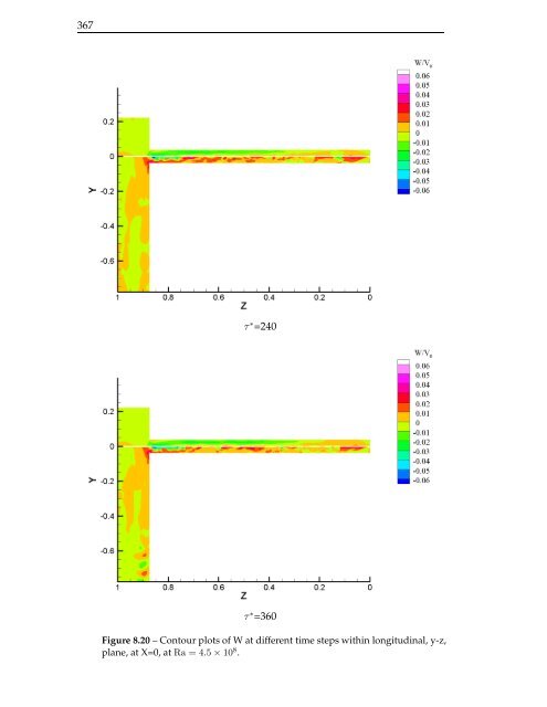
- Page 366 and 367: 365 τ ∗ =240 τ ∗ =360 Figure
- Page 370 and 371: 369 τ ∗ =0 τ ∗ =120 τ ∗ =2
- Page 372 and 373: 371 τ ∗ =0 τ ∗ =120 τ ∗ =2
- Page 374 and 375: 373 Z=0.69 τ ∗ =0 τ ∗ =120 τ
- Page 376 and 377: 375 Time-averaged Steady state Figu
- Page 378 and 379: 377 Time-averaged Z=0.23 Z=0.46 Z=0
- Page 380 and 381: 379 8.5 Steady-state simulation (Ra
- Page 382 and 383: 381 reduces towards the sides and a
- Page 384 and 385: 383 Figure 8.33 - Contour plots of
- Page 386 and 387: 385 Z=0.23 Z=0.46 Z=0.69 Z=0.87 Z=0
- Page 388 and 389: 387 Z=0.88 Z=0.92 Z=1.0 Z=0.88 Z=0.
- Page 390 and 391: 389 Z=0.88 Z=0.92 Z=1.0 Z=0.88 Z=0.
- Page 392 and 393: 391 Y=0.22 (Inlet) Y=-0.11 Y=0.22 (
- Page 394 and 395: 393 The contours of the instantaneo
- Page 396 and 397: 395 total turbulent kinetic energy
- Page 398 and 399: 397 τ ∗ =240 τ ∗ =360 Figure
- Page 400 and 401: 399 τ ∗ =240 τ ∗ =360 Figure
- Page 402 and 403: 401 τ ∗ =0 τ ∗ =300 τ ∗ =6
- Page 404 and 405: 403 τ ∗ =0 τ ∗ =300 τ ∗ =6
- Page 406 and 407: 405 Z=0.69 τ ∗ =0 τ ∗ =120 τ
- Page 408 and 409: 407 Time-averaged Steady state Figu
- Page 410 and 411: 409 Time-averaged Z=0.23 Z=0.46 Z=0
- Page 412 and 413: 411 8.7 Closing remarks In this cha
- Page 414 and 415: Chapter 9 Conclusions and Future Wo
- Page 416 and 417: 415 60 ◦ Stable Case Buoyancy-dri
- Page 418 and 419:
417 using the k-ε-AWF are in close
- Page 420 and 421:
419 the spanwise direction, suggest
- Page 422 and 423:
421 results of the 3D numerical sim
- Page 424 and 425:
423 stable and unstable configurati
- Page 426 and 427:
425 penetration was concerned, the
- Page 428 and 429:
427 convection within rectangular c
- Page 430 and 431:
429 [8] D. Cooper, T. Craft, K. Est
- Page 432 and 433:
431 [28] R. Boudjemadi, V. Maupu, D
- Page 434 and 435:
433 [47] D. Naot, A. Shavit, and M.
- Page 436 and 437:
435 [68] K. Hanjalić. Achievements
- Page 438:
437 T V/V 0 v rms /V 0 1 0.8 0.6 0.