A Displacement Metric for Finite Sets of Rigid Body Displacements
A Displacement Metric for Finite Sets of Rigid Body Displacements
A Displacement Metric for Finite Sets of Rigid Body Displacements

Create successful ePaper yourself
Turn your PDF publications into a flip-book with our unique Google optimized e-Paper software.
2<br />
1.5<br />
1<br />
0.5<br />
0<br />
−0.5<br />
−1<br />
M3<br />
M4<br />
M2<br />
M1<br />
M5<br />
M6<br />
PF<br />
F<br />
M7<br />
−1.5 −1 −0.5 0 0.5 1 1.5 2<br />
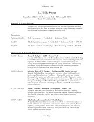
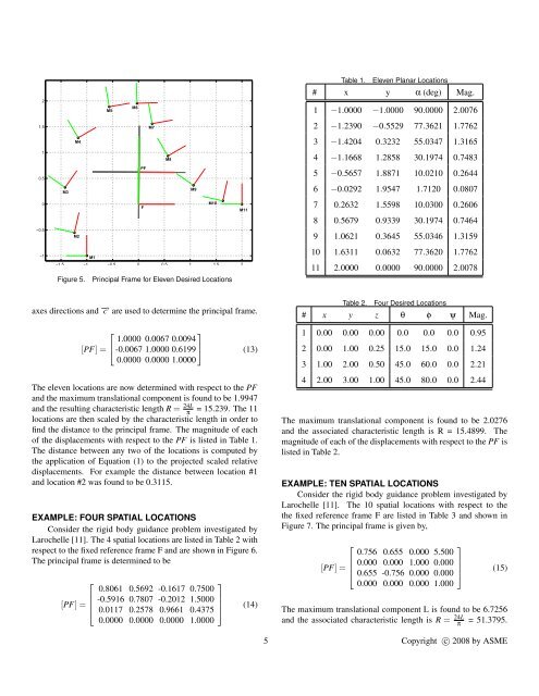
Figure 5. Principal Frame <strong>for</strong> Eleven Desired Locations<br />
axes directions and −→ c are used to determine the principal frame.<br />
M8<br />
⎡<br />
⎤<br />
1.0000 0.0067 0.0094<br />
[PF] = ⎣ -0.0067 1.0000 0.6199 ⎦ (13)<br />
0.0000 0.0000 1.0000<br />
The eleven locations are now determined with respect to the PF<br />
and the maximum translational component is found to be 1.9947<br />
and the resulting characteristic length R = 24L<br />
π = 15.239. The 11<br />
locations are then scaled by the characteristic length in order to<br />
find the distance to the principal frame. The magnitude <strong>of</strong> each<br />
<strong>of</strong> the displacements with respect to the PF is listed in Table 1.<br />
The distance between any two <strong>of</strong> the locations is computed by<br />
the application <strong>of</strong> Equation (1) to the projected scaled relative<br />
displacements. For example the distance between location #1<br />
and location #2 was found to be 0.3115.<br />
EXAMPLE: FOUR SPATIAL LOCATIONS<br />
Consider the rigid body guidance problem investigated by<br />
Larochelle [11]. The 4 spatial locations are listed in Table 2 with<br />
respect to the fixed reference frame F and are shown in Figure 6.<br />
The principal frame is determined to be<br />
⎡<br />
⎤<br />
0.8061 0.5692 -0.1617 0.7500<br />
⎢<br />
[PF] = ⎢ -0.5916 0.7807 -0.2012 1.5000 ⎥<br />
⎣ 0.0117 0.2578 0.9661 0.4375 ⎦<br />
0.0000 0.0000 0.0000 1.0000<br />
M9<br />
M10<br />
M11<br />
(14)<br />
Table 1. Eleven Planar Locations<br />
# x y α (deg) Mag.<br />
1 −1.0000 −1.0000 90.0000 2.0076<br />
2 −1.2390 −0.5529 77.3621 1.7762<br />
3 −1.4204 0.3232 55.0347 1.3165<br />
4 −1.1668 1.2858 30.1974 0.7483<br />
5 −0.5657 1.8871 10.0210 0.2644<br />
6 −0.0292 1.9547 1.7120 0.0807<br />
7 0.2632 1.5598 10.0300 0.2606<br />
8 0.5679 0.9339 30.1974 0.7464<br />
9 1.0621 0.3645 55.0346 1.3159<br />
10 1.6311 0.0632 77.3620 1.7762<br />
11 2.0000 0.0000 90.0000 2.0078<br />
Table 2. Four Desired Locations<br />
# x y z θ φ ψ Mag.<br />
1 0.00 0.00 0.00 0.0 0.0 0.0 0.95<br />
2 0.00 1.00 0.25 15.0 15.0 0.0 1.24<br />
3 1.00 2.00 0.50 45.0 60.0 0.0 2.21<br />
4 2.00 3.00 1.00 45.0 80.0 0.0 2.44<br />
The maximum translational component is found to be 2.0276<br />
and the associated characteristic length is R = 15.4899. The<br />
magnitude <strong>of</strong> each <strong>of</strong> the displacements with respect to the PF is<br />
listed in Table 2.<br />
EXAMPLE: TEN SPATIAL LOCATIONS<br />
Consider the rigid body guidance problem investigated by<br />
Larochelle [11]. The 10 spatial locations with respect to the<br />
the fixed reference frame F are listed in Table 3 and shown in<br />
Figure 7. The principal frame is given by,<br />
⎡<br />
⎤<br />
0.756 0.655 0.000 5.500<br />
⎢<br />
[PF] = ⎢ 0.000 0.000 1.000 0.000 ⎥<br />
⎣ 0.655 -0.756 0.000 0.000 ⎦<br />
0.000 0.000 0.000 1.000<br />
(15)<br />
The maximum translational component L is found to be 6.7256<br />
and the associated characteristic length is R = 24L<br />
π = 51.3795.<br />
5 Copyright c○ 2008 by ASME