GREENSTAR™ 2100 & 2600 Display - StellarSupport - John Deere
GREENSTAR™ 2100 & 2600 Display - StellarSupport - John Deere
GREENSTAR™ 2100 & 2600 Display - StellarSupport - John Deere

You also want an ePaper? Increase the reach of your titles
YUMPU automatically turns print PDFs into web optimized ePapers that Google loves.
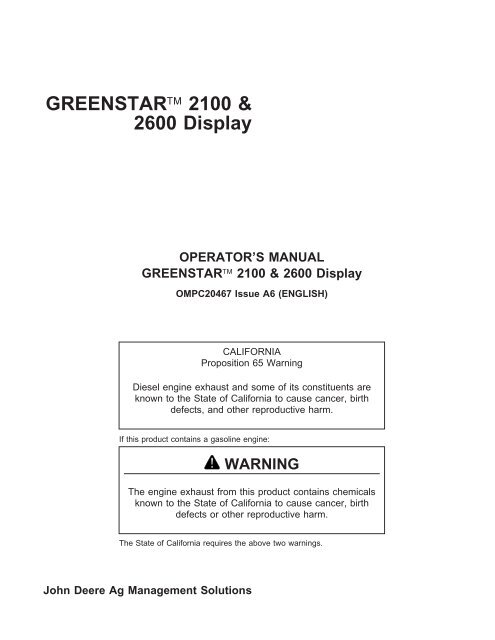
GREENSTAR <strong>2100</strong> &<br />
<strong>2600</strong> <strong>Display</strong><br />
OPERATOR’S MANUAL<br />
GREENSTAR <strong>2100</strong> & <strong>2600</strong> <strong>Display</strong><br />
OMPC20467 Issue A6 (ENGLISH)<br />
CALIFORNIA<br />
Proposition 65 Warning<br />
Diesel engine exhaust and some of its constituents are<br />
known to the State of California to cause cancer, birth<br />
defects, and other reproductive harm.<br />
If this product contains a gasoline engine:<br />
WARNING<br />
The engine exhaust from this product contains chemicals<br />
known to the State of California to cause cancer, birth<br />
defects or other reproductive harm.<br />
The State of California requires the above two warnings.<br />
<strong>John</strong> <strong>Deere</strong> Ag Management Solutions
Foreword<br />
WARRANTY: Please reference your purchase<br />
agreement for warranty statement. <strong>John</strong> <strong>Deere</strong><br />
products are designed and tested to meet the<br />
requirements of agricultural environments. Like all<br />
electronic products, touch screens are vulnerable to<br />
damage, either deliberate or through neglect. Damage<br />
due to neglect is not covered under <strong>John</strong> <strong>Deere</strong><br />
product warranty. It is important to follow proper use<br />
guidelines with the GSD<strong>2600</strong> touch screen. Under no<br />
circumstance should you contact the touch screen with<br />
an object harder or sharper than a fingertip (pen,<br />
pencil point, or any metal objects). Heavy pressure can<br />
also damage underlying components and void the<br />
touch screen warranty. Light amounts of pressure, if<br />
exerted continuously, can degrade touch screen<br />
reliability. The GSD<strong>2600</strong> should be stored near room<br />
temperature during the off season and in the original<br />
shipping container with no items contacting the<br />
touchscreen surface.<br />
INTENDED USE: This system is designed solely for<br />
use in customary agriculture or similar operations. Use<br />
in any other way is considered as contrary to intended<br />
use. Manufacturer accepts no liability for damage or<br />
injury resulting from misuse, and these risks must be<br />
borne solely by user. Compliance with and strict<br />
adherence to conditions of operation, service and<br />
repair as specified by manufacturer also constitute<br />
essential elements for intended use.<br />
READ THIS MANUAL carefully to learn how to operate<br />
and service your system correctly. Failure to do so<br />
could result in personal injury or equipment damage.<br />
This manual and safety signs on the system may also<br />
Introduction<br />
be available in other languages. (See your <strong>John</strong> <strong>Deere</strong><br />
dealer to order.)<br />
THIS MANUAL SHOULD BE CONSIDERED a<br />
permanent part of your system and should remain with<br />
system when you sell it.<br />
MEASUREMENTS in this manual are given in both<br />
metric and customary U.S. unit equivalents. Use only<br />
correct replacement parts and fasteners. Metric and<br />
inch fasteners may require a specific metric or inch<br />
wrench.<br />
RIGHT-HAND AND LEFT-HAND sides are determined<br />
by facing direction of forward travel.<br />
WRITE PRODUCT IDENTIFICATION NUMBERS<br />
(P.I.N.) in Specification or Identification Numbers<br />
section. Accurately record all numbers to help in<br />
tracing system should it be stolen. Your dealer also<br />
needs these numbers when you order parts. File<br />
identification numbers in a secure place off machine.<br />
THIS SYSTEM SHOULD BE OPERATED, serviced<br />
and repaired only by persons familiar with all its<br />
particular characteristics and acquainted with relevant<br />
safety rules (accident prevention). Accident prevention<br />
regulations, all other generally recognized regulations<br />
on safety and occupational medicine and road traffic<br />
regulations must be observed at all times. Any<br />
arbitrary modifications carried out on this system will<br />
relieve manufacturer of all liability for any resulting<br />
damage or injury.<br />
OUO6050,0001500 –19–09JAN06–1/1<br />
011906<br />
PN=2
Contents<br />
Page Page<br />
Safety ................................05-1 GreenStar General<br />
GREENSTAR2 PRO softkey ...............40-1<br />
Updating Software<br />
RESOURCES/CONDITIONS softkey .........40-2<br />
GS2 Live Update ........................10-1 EQUIPMENT softkey .....................40-3<br />
Loading Software ........................10-1 MACHINE tab. ..........................40-3<br />
IMPLEMENT 1 tab .......................40-6<br />
General Information<br />
Theory of Operation ......................15-1<br />
Front of <strong>Display</strong> .........................15-3<br />
Back of <strong>Display</strong> .........................15-4<br />
<strong>Display</strong> Control. .........................15-4<br />
<strong>Display</strong> Secondary Navigation ..............15-5<br />
Data Card. .............................15-6<br />
IMPLEMENT 2 and IMPLEMENT 3 tab ......40-12<br />
MAPPING softkey. ......................40-13<br />
Mapping Harvest .......................40-14<br />
MAPS tab. ............................40-15<br />
BOUNDARIES tab ......................40-17<br />
FLAGS tab ............................40-18<br />
Screen Layout ..........................15-8 Guidance<br />
GUIDANCE softkey ......................45-1<br />
<strong>Display</strong> Navigation<br />
Power Up ..............................20-1<br />
Selecting a Desired Input Field with <strong>Display</strong><br />
Control ..............................20-2<br />
Input Fields. ............................20-2<br />
VIEW tab ..............................45-3<br />
GUIDANCE SETTINGS tab ................45-8<br />
Turning View ...........................45-8<br />
Turn Predictor ..........................45-9<br />
Recording Turn Points ....................45-9<br />
Predicting Turn Points ...................45-10<br />
softkeys and Icons<br />
ISO Standard Icons ......................25-1<br />
Performance Monitor .....................25-1<br />
Message Center .........................25-2<br />
<strong>Display</strong> ................................25-4<br />
StarFire iTC ............................25-6<br />
Lead Compensation .....................45-12<br />
SHIFT TRACK SETTINGS tab .............45-12<br />
Track 0 Setup<br />
Straight Track Mode ...................45-14<br />
Curve Track Mode ....................45-15<br />
Circle Track Mode. ....................45-16<br />
GreenStar2 Pro .........................25-8<br />
Row Finder Mode .....................45-17<br />
AutoTrac System .......................45-17<br />
AutoTrac Status Pie .....................45-18<br />
<strong>Display</strong> Setup Steering Sensitivity ......................45-21<br />
<strong>Display</strong> Software Activations. ...............30-1 AutoTrac Tractors<br />
OBTAINING ACTIVATION CODE & Enabling System ......................45-23<br />
ACTIVATING SOFTWARE IN DISPLAY .....30-2 Activating System .....................45-24<br />
<strong>Display</strong> Deactivating System ...................45-25<br />
<strong>Display</strong> Soft-key (F) ....................30-3 AutoTrac Sprayers<br />
Settings Soft-key (G). ...................30-6 Enabling System ......................45-26<br />
Auxiliary Controls Soft-key (H) ............30-7 Activating System .....................45-27<br />
Diagnostics Soft-key (I) ..................30-8 Deactivating System ...................45-28<br />
AutoTrac Combines<br />
Home Page Layout<br />
Enabling System ......................45-28<br />
Home Page Layout. ......................35-1<br />
Harvest Home Page Layout Options .........35-4<br />
Continued on next page<br />
All information, illustrations and specifications in this manual are based on<br />
the latest information available at the time of publication. The right is<br />
reserved to make changes at any time without notice.<br />
COPYRIGHT © 2006<br />
DEERE & COMPANY<br />
Moline, Illinois<br />
All rights reserved<br />
A <strong>John</strong> <strong>Deere</strong> ILLUSTRUCTION ® Manual<br />
i 011906<br />
PN=1
Contents<br />
Page Page<br />
Activating System .....................45-29 Moisture Curve ........................60-8<br />
Deactivating System ...................45-30 Selection Recording ....................60-9<br />
AutoTrac Universal<br />
Accuracy. ...........................45-30<br />
Setting Yield/Area Units .................60-9<br />
General Information ...................45-31<br />
Start-Up Screen ......................45-32<br />
Setup ..............................45-33<br />
Enabling System ......................45-34<br />
Activating System .....................45-35<br />
Deactivating System ...................45-36<br />
Information ..........................45-36<br />
Circle Track ...........................45-37<br />
Curve Track ...........................45-40<br />
AutoTrac Accuracy ......................45-43<br />
Harvest Monitor—Picker<br />
Original GreenStar Monitor. ................65-1<br />
Picker<br />
Flow Chart ...........................65-1<br />
Setting Yield Units .....................65-2<br />
Setting Area Units. .....................65-2<br />
Setting Rows and Spacing ...............65-2<br />
Calibration. ...........................65-5<br />
Row Compensation. ....................65-6<br />
Quick Calibration. ......................65-6<br />
Standard Calibration ....................65-7<br />
Documentation Manual Adjustment of Calibration Factor. ....65-8<br />
Turning Documentation On/Off ..............50-1<br />
How Documentation Organizes Data .........50-1<br />
Recording ............................65-9<br />
DOCUMENTATION softkey ................50-2<br />
Operations .............................50-3<br />
Harvest Setup ..........................50-4<br />
Performance Monitor<br />
Setup Performance Monitor ................70-1<br />
Changing Harvest Settings .................50-5<br />
Task Notes. ............................50-7<br />
Controllers .............................50-8<br />
TOTALS softkey .........................50-9<br />
Harvest Totals .........................50-10<br />
Using Documentation with <strong>John</strong> <strong>Deere</strong><br />
Air Carts ............................50-12<br />
Required and Optional Items For<br />
Documentation .......................50-12<br />
Map Based Prescriptions .................50-13<br />
Coverage Map .........................50-15<br />
Connecting Non-<strong>Deere</strong> Controllers ..........50-16<br />
Swath Control Pro—Enabling ..............50-17<br />
Swath Control Pro—Setup ................50-22<br />
Swath Control Pro—Coverage Map .........50-26<br />
StarFire iTC Receiver<br />
STARFIRE ITC softkey. ...................75-1<br />
INFO tab ..............................75-2<br />
SETUP tab .............................75-3<br />
Correction Mode. ........................75-3<br />
Correction Frequency .....................75-3<br />
Mount Direction .........................75-4<br />
Fore/Aft ...............................75-5<br />
Height. ................................75-6<br />
QuickStart .............................75-6<br />
Hours On After Shutdown. .................75-7<br />
TCM Calibration .........................75-7<br />
ACTIVATIONS tab ......................75-10<br />
SERIAL PORT tab ......................75-11<br />
RTK softkey ...........................75-11<br />
Original GreenStar Monitor<br />
Compatible Systems. .....................55-1<br />
Operating Original GreenStar Monitor. ........55-1<br />
Vehicle ...............................75-13<br />
Vehicle Repeater .......................75-14<br />
Quick Survey Mode .....................75-15<br />
Absolute Base Mode ....................75-16<br />
Harvest Monitor—Combine<br />
Original GreenStar Monitor. ................60-1<br />
Combine<br />
RTK Network Configuration ...............75-17<br />
SATELLITE INFORMATION softkey. ........75-19<br />
DIAGNOSTIC softkey. ...................75-21<br />
Starting ..............................60-1<br />
Defining Header .......................60-2<br />
Calibration. ...........................60-3<br />
Low Flow Compensation<br />
Connecting RS-232 GPS Receivers<br />
Connecting RS-232 GPS Receivers ..........80-1<br />
Procedure--Optional. ..................60-5 ISO Implements<br />
Manually Adjusting Calibration Factor .......60-6 ISO Implements .........................85-1<br />
SETUP - MOISTURE CORRECTION .......60-6<br />
Moisture Correction. ....................60-7<br />
Operating ISO Implement ..................85-2<br />
Moisture Alarm ........................60-8 Continued on next page<br />
ii 011906<br />
PN=2
Page<br />
Troubleshooting and Diagnostics<br />
Message Center .........................90-1<br />
Resetting <strong>Display</strong> ........................90-6<br />
Warning Screens ........................90-7<br />
Diagnostic Addresses. ....................90-8<br />
Guidance Warnings .....................90-11<br />
Trouble Code Pop-Up Boxes—Platform<br />
Core Software. .......................90-13<br />
Trouble Code Pop-Up Boxes—Guidance<br />
Software ............................90-15<br />
Trouble Code Pop-Up Boxes—<br />
Documentation Software ................90-17<br />
AutoTrac Universal ......................90-19<br />
AutoTrac Universal Stop Codes ............90-21<br />
GreenStar Diagnostics ...................90-22<br />
Fault Codes—StarFire iTC ................90-22<br />
Diagnostic Trouble Codes—StarFire iTC .....90-25<br />
Specifications<br />
Metric Bolt and Screw Torque Values. ........95-1<br />
Unified Inch Bolt and Screw Torque Values ....95-2<br />
Contents<br />
iii 011906<br />
PN=3
Contents<br />
iv 011906<br />
PN=4
Recognize Safety Information<br />
This is a safety-alert symbol. When you see this symbol<br />
on your machine or in this manual, be alert to the<br />
potential for personal injury.<br />
Follow recommended precautions and safe operating<br />
practices.<br />
Understand Signal Words<br />
A signal word—DANGER, WARNING, or CAUTION—is<br />
used with the safety-alert symbol. DANGER identifies the<br />
most serious hazards.<br />
DANGER or WARNING safety signs are located near<br />
specific hazards. General precautions are listed on<br />
CAUTION safety signs. CAUTION also calls attention to<br />
safety messages in this manual.<br />
Follow Safety Instructions<br />
Safety<br />
Carefully read all safety messages in this manual and on<br />
your machine safety signs. Keep safety signs in good<br />
condition. Replace missing or damaged safety signs. Be<br />
sure new equipment components and repair parts include<br />
the current safety signs. Replacement safety signs are<br />
available from your <strong>John</strong> <strong>Deere</strong> dealer.<br />
Learn how to operate the machine and how to use<br />
controls properly. Do not let anyone operate without<br />
instruction.<br />
Keep your machine in proper working condition.<br />
Unauthorized modifications to the machine may impair the<br />
function and/or safety and affect machine life.<br />
If you do not understand any part of this manual and need<br />
assistance, contact your <strong>John</strong> <strong>Deere</strong> dealer.<br />
T81389 –UN–07DEC88<br />
DX,ALERT –19–29SEP98–1/1<br />
TS187 –19–30SEP88<br />
DX,SIGNAL –19–03MAR93–1/1<br />
TS201 –UN–23AUG88<br />
DX,READ –19–03MAR93–1/1<br />
05-1 011906<br />
PN=5
Prepare for Emergencies<br />
Be prepared if a fire starts.<br />
Keep a first aid kit and fire extinguisher handy.<br />
Safety<br />
Keep emergency numbers for doctors, ambulance service,<br />
hospital, and fire department near your telephone.<br />
Practice Safe Maintenance<br />
Understand service procedure before doing work. Keep<br />
area clean and dry.<br />
Never lubricate, service, or adjust machine while it is<br />
moving. Keep hands, feet , and clothing from<br />
power-driven parts. Disengage all power and operate<br />
controls to relieve pressure. Lower equipment to ground.<br />
Stop engine, remove key, and set parking brake. Allow<br />
machine to cool.<br />
Securely support any machine elements that must be<br />
raised for service work.<br />
Keep all parts in good condition and properly installed. Fix<br />
damage immediately. Replace worn or broken parts.<br />
Remove any buildup of grease, oil, or debris.<br />
Disconnect battery ground cable (-) before making<br />
adjustments on electrical systems or welding on machine.<br />
Read Operator Manuals for ISOBUS Implements<br />
In addition to GreenStar Applications, this display can<br />
be used as a display device for any implement that<br />
meets ISO 11783 standard. This includes capability to<br />
control ISOBUS implements. When used in this<br />
manner, information and implement control functions<br />
placed on the display are provided by the implement<br />
TS291 –UN–23AUG88<br />
DX,FIRE2 –19–03MAR93–1/1<br />
TS218 –UN–23AUG88<br />
OUO6050,0001494 –19–20OCT05–1/1<br />
and are the responsibility of the implement<br />
manufacturer. Some of these implement functions<br />
could provide a hazard either to the Operator or a<br />
bystander. Read the operator manual provided by the<br />
implement manufacturer and observe all safety<br />
messages in manual and on implement prior to use.<br />
OUO6050,0001495 –19–17NOV05–1/1<br />
05-2 011906<br />
PN=6
GS2 Live Update<br />
<strong>John</strong> <strong>Deere</strong> AMS periodically develops software<br />
updates to your GreenStar 2 system to deliver new<br />
system enhancements, or performance improvements.<br />
This could include updated software for your GS2<br />
display, as well as many other components.<br />
The GS2 Live Update is a desktop software application<br />
that will automatically alert you of recent updates to<br />
Loading Software<br />
IMPORTANT: IMPORTANT: If changes are made<br />
while machine is in auxiliary mode,<br />
turn key off and wait for display’s<br />
power light to turn off before starting<br />
the ignition. This allows display to<br />
shut down and save data.<br />
IMPORTANT: Do not turn off power or remove<br />
data card while display is<br />
reprogramming. Doing so can<br />
damage display and put software in<br />
an irrecoverable state.<br />
Verify that display has the latest software available. To<br />
acquire the latest software visit<br />
www.<strong>StellarSupport</strong>.com or contact a <strong>John</strong> <strong>Deere</strong><br />
dealer.<br />
After new software has been downloaded to data card,<br />
simply insert data card in display and system will show<br />
a screen prompting operator to reprogram display. If<br />
operator does not choose to reprogram system,<br />
reprogramming alarm will appear during every<br />
power-up cycle if the data card is still inserted.<br />
Updating Software<br />
your GS2 system, and walk you through the<br />
downloading process. To install the GS2 Live Update,<br />
insert the CD into your CD ROM drive and follow the<br />
on screen prompts. If no prompts appear, double click<br />
on My Computer, and find the drive associated with<br />
your CD ROM drive. Run the program labeled<br />
“GS2LiveUpdateSetup.exe”.<br />
OUO6050,0001752 –19–18JAN06–1/1<br />
To install this software update, press the button to<br />
continue:<br />
Updating software - Warning: Do not power down<br />
display or remove card.<br />
The update was successfully installed. Press the<br />
button to continue. - Please cycle power.<br />
The system is restarting, please wait...<br />
If software update was unsuccessful this message will<br />
be given: The software update was unsuccessfully.<br />
See the message center.<br />
To manually load a different software version to a<br />
component:<br />
• Choose component from list on Message Center -<br />
Reprogram Device Screen<br />
• Push REPROGRAM DEVICE button<br />
• Choose software version from the drop-down box<br />
and press enter.<br />
OUO6050,0001753 –19–18JAN06–1/1<br />
10-1 011906<br />
PN=7
Theory of Operation<br />
IMPORTANT: It is important to follow proper use<br />
guidelines with the GSD<strong>2600</strong> touch<br />
screen. Under no circumstance<br />
should you contact the touch screen<br />
with an object harder or sharper<br />
than a fingertip (pen, pencil point, or<br />
any metal objects). Heavy pressure<br />
can also damage underlying<br />
components and void the touch<br />
screen warranty. Light amounts of<br />
pressure, if exerted continuously,<br />
can degrade touch screen reliability.<br />
The GSD<strong>2600</strong> should be stored near<br />
room temperature during the off<br />
season and in the original shipping<br />
container with no items contacting<br />
the touchscreen surface.<br />
The <strong>2100</strong> & <strong>2600</strong> GreenStar displays are primarily<br />
used as an operator interface for guidance and<br />
documentation applications.<br />
The <strong>2600</strong> GreenStar display’s primary navigational<br />
point is the touchscreen which allows the operator to<br />
input information by touching the screen. The <strong>2600</strong><br />
can also use the display control which allows use of<br />
input buttons and thumb wheel.<br />
The <strong>2100</strong> GreenStar display’s primary navigational<br />
point is the display control which allows the operator to<br />
input information using buttons and a thumb wheel.<br />
Selected field, button, or softkey will appear with a<br />
highlighted border.<br />
GreenStar Basics Software<br />
The <strong>2100</strong> and <strong>2600</strong> display come standard with a<br />
basic software feature set, including:<br />
General Information<br />
• Manual Guidance<br />
• Documentation (field and harvest)<br />
• On-Screen Mapping<br />
• Prescriptions<br />
When connected to a GPS receiver, the system allows<br />
the operator to manually drive vehicle with the aid of<br />
GPS. When combined with an optional AutoTrac<br />
activation, and vehicle steering kit, system can<br />
automatically guide machine though the field.<br />
Documentation can be used to record data tied to GPS<br />
coordinates. On some machines, rates, yield,<br />
implement width, or other information will be recorded<br />
from the vehicle CAN bus. The displays can also be<br />
connected to certain 3rd party controllers to record rate<br />
information. This data is collected on the compact flash<br />
card and can be downloaded into desktop software to<br />
produce maps and reports of field activities.<br />
On-screen mapping uses GPS, and a recording source<br />
to create real time maps of field activities. Operators<br />
will be able to see the areas of the field they have<br />
covered.<br />
Original GreenStar Monitor function can be used to<br />
operate selected <strong>John</strong> <strong>Deere</strong> implements as they<br />
would normally be used with the original GreenStar<br />
display. The <strong>2100</strong> and <strong>2600</strong> may also be mounted in<br />
tandem with an original GreenStar display. In this<br />
configuration, <strong>John</strong> <strong>Deere</strong> machine specific information<br />
will display on the original GreenStar display, and GS2<br />
Basics applications will be shown on the <strong>2100</strong> or <strong>2600</strong>.<br />
The <strong>2100</strong> and <strong>2600</strong> displays have an integrated<br />
performance monitor that can be used to record area<br />
and other data based on implement width and ground<br />
speed.<br />
Continued on next page<br />
OUO6050,00016EA –19–17JAN06–1/2<br />
15-1 011906<br />
PN=8
<strong>Display</strong> can also be used for machines and systems<br />
that conform to implementation level 2 of International<br />
Organization for Standardization (ISO) 11783. The<br />
purpose of ISO 11783 is to enable electronic units to<br />
communicate with each other providing a standardized<br />
system that is easy to read and understand. Utilizing<br />
straight-forward customizable controls that are<br />
separate from the display itself, the operator can use<br />
the display as a tractor performance monitor and a<br />
monitor for an ISO 11783 compliant implement.<br />
General Information<br />
From time to time, <strong>John</strong> <strong>Deere</strong> AMS publishes<br />
software updates to the GS2 system over the internet<br />
at www.<strong>StellarSupport</strong>.com. Each display also comes<br />
with a GS2 Live Update CD. Live Update can be<br />
installed on an internet connected PC and alert the<br />
user when updates to the display are available. It will<br />
then walk the user through the downloading process.<br />
The download can be stored on a data card, and<br />
inserted into the display to complete the update.<br />
OUO6050,00016EA –19–17JAN06–2/2<br />
15-2 011906<br />
PN=9
Front of <strong>Display</strong><br />
IMPORTANT: Do not remove 12 volt power from<br />
display until the LED light is black.<br />
Prematurely removing power (green or<br />
orange light status) may cause loss of<br />
data and/or the display to lose<br />
functionality. It may take up to 20<br />
seconds after removing key power for<br />
the LED light to completely go black.<br />
The data card should not be removed<br />
during this period also.<br />
<strong>Display</strong> (A) is located in cab and allows operator to view<br />
instantaneous information from seat while operating<br />
vehicle.<br />
Power light (B) will indicate power mode of display:<br />
• green—display on and cold boot up<br />
• flashing green—warm boot-up<br />
• orange—standby<br />
• off—shutdown<br />
Cold boot-up occurs when display has been powered<br />
down for over 24 hours and takes 20-25 seconds to<br />
power up.<br />
Warm boot-up occurs when display has been operating in<br />
the last 24 hours and takes 1-3 seconds to power up.<br />
IMPORTANT: Always clean screen on <strong>2600</strong> display<br />
with power off. Cleaning screen while<br />
operating could result in unintended<br />
button presses.<br />
General Information<br />
To clean display, power down and wipe screen with a soft<br />
cloth sprayed with a non-ammonia based cleaner such as<br />
<strong>John</strong> <strong>Deere</strong> glass or multipurpose cleaner.<br />
<strong>Display</strong><br />
A—<strong>Display</strong><br />
B—Power Light (reference only)<br />
PC8572 –UN–03AUG05<br />
OUO6050,00016EB –19–08DEC05–1/1<br />
15-3 011906<br />
PN=10
Back of <strong>Display</strong><br />
Backside of <strong>Display</strong> contains:<br />
• <strong>Display</strong> Mounting Holes—attach to bracket on machine<br />
• Secondary Navigational point—provides backup<br />
navigation with display<br />
• Data Card Door/Slot—houses data card used for data<br />
collection and saving selected display and implement<br />
settings.<br />
• <strong>Display</strong> Connector—connects vehicle wiring harness<br />
plugs with display for system power and<br />
communication.<br />
NOTE: Backside of display will all have label with display<br />
model and serial number on it.<br />
A—<strong>Display</strong> Mounting Holes<br />
B—Secondary Navigation<br />
C—<strong>Display</strong> Connector<br />
D—Compact Flash Door<br />
<strong>Display</strong> Control<br />
CAUTION: Do not mount display control on the<br />
side of dual displays (<strong>2100</strong>/<strong>2600</strong> and GSD4).<br />
This blocks the operator’s view and overloads<br />
the bracket. Mount the display control<br />
elsewhere.<br />
General Information<br />
The display control is the primary navigational point on the<br />
GreenStar <strong>Display</strong> <strong>2100</strong> (and <strong>2600</strong> if equipped).<br />
The display control contains 10 available short-cut<br />
softkeys A-J, Thumb Wheel (A), ENTER button (B),<br />
CANCEL button (C), and MENU button (D).<br />
A—Thumb Wheel<br />
B—ENTER button<br />
C—CANCEL button<br />
D—MENU button<br />
Backside of <strong>Display</strong><br />
<strong>Display</strong> Control<br />
PC8863 –UN–02NOV05<br />
OUO6050,00016EC –19–08DEC05–1/1<br />
PC8864 –UN–09JAN06<br />
OUO6050,00016ED –19–08DEC05–1/1<br />
15-4 011906<br />
PN=11
<strong>Display</strong> Secondary Navigation<br />
General Information<br />
Secondary display controls consist of five buttons located<br />
on backside of display. They provide backup navigation in<br />
the event that the primary display controls are not<br />
communicating with display.<br />
ENTER button (A) and CANCEL button (D) operate the<br />
same as they do on the primary display controls.<br />
Up Arrow (B) and Down Arrow (C) simulate thumb wheel<br />
operation on display control.<br />
DISPLAY RESET button (E) resets display without cycling<br />
power on vehicle. Hold for 3 seconds to reboot.<br />
A—Enter<br />
B—Up Arrow<br />
C—Down Arrow<br />
D—Cancel<br />
E—<strong>Display</strong> Reset<br />
<strong>Display</strong> Secondary Navigation<br />
PC8580 –UN–17AUG05<br />
OUO6050,00016EE –19–08DEC05–1/1<br />
15-5 011906<br />
PN=12
Data Card<br />
IMPORTANT: Do not remove 12 volt power from<br />
display until the LED light is black.<br />
Prematurely removing power (green or<br />
orange light status) may cause loss of<br />
data and/or the display to lose<br />
functionality. It may take up to 20<br />
seconds after removing key power for<br />
the LED light to completely go black.<br />
The data card should not be removed<br />
during this period also.<br />
IMPORTANT: Data card must be in display during<br />
operation or system functionality will<br />
deteriorate.<br />
IMPORTANT: Do not remove data card while display<br />
is reprogramming. Doing so can<br />
damage display and put software in an<br />
irrecoverable state.<br />
Any time machine configuration<br />
changes are made, the power must be<br />
cycled on the display to allow changes<br />
to take place.<br />
General Information<br />
After configuring machine and<br />
implement setup, make sure key power<br />
is turned off and LED light is able to go<br />
to black before operating in the field.<br />
This will allow all setup information to<br />
be saved to the data card.<br />
Steps for Data Card Insertion<br />
1. Open the card slot door by pressing forward on the<br />
door latch tab, and continue to press forward until the<br />
door springs open.<br />
2. Wait for message stating that Data Card can be<br />
ejected.<br />
3. The side of the data card that has the ridge along the<br />
bottom edge should be facing the operator as it is<br />
inserted. It cannot be inserted with the opposite side<br />
facing the operator.<br />
A—Data Card<br />
Continued on next page<br />
Data Card in <strong>Display</strong><br />
PC8865 –UN–02NOV05<br />
OUO6050,00016EF –19–19JAN06–1/2<br />
15-6 011906<br />
PN=13
General Information<br />
4. Press the data card into the slot until it clicks into place<br />
and pushes the eject button all the way out. It has a<br />
similar feel to inserting a PCMCIA card into a Mobile<br />
Processor.<br />
5. Close the card slot door.<br />
Steps for Data Card Removal<br />
1. Open the card slot door.<br />
2. Press the eject button located directly below the card<br />
slot inside the card slot door. This is very similar to<br />
removing a PCMCIA card from a Mobile Processor.<br />
3. The data card will pop out enough to grab it with your<br />
fingers and remove it from the card slot.<br />
OUO6050,00016EF –19–19JAN06–2/2<br />
15-7 011906<br />
PN=14
Screen Layout<br />
General Information<br />
Screen Layout<br />
A—Home C—Message Center D—softkeys E—Application Info Area<br />
B—Menu<br />
NOTE: <strong>Display</strong> screen illustrated on following pages<br />
are provided for reference only. Actual screens<br />
may appear differently due to connection of<br />
optional devices and/or software versions.<br />
Home (A), Menu (B) and Message Center (C)<br />
selections will be on every screen.<br />
• Home selection—allows operator to view Home<br />
Page.<br />
• Menu selection—allows operator to view a list of<br />
available applications.<br />
• Message Center selection—allows operator to view<br />
cautions, warning messages, diagnostic information.<br />
(See SETUP MESSAGE CENTER in <strong>Display</strong><br />
Message Center section.)<br />
Selecting one of the softkeys (D) will cause a new<br />
page to appear or a process to be started.<br />
OUO6050,00016F0 –19–08DEC05–1/1<br />
15-8 011906<br />
PN=15<br />
PC8577 –UN–02NOV05
Power Up<br />
IMPORTANT: Do not remove 12 volt power from<br />
display until the LED light is black.<br />
Prematurely removing power (green<br />
or orange light status) may cause<br />
loss of data and/or the display to<br />
lose functionality. It may take up to<br />
20 seconds after removing key<br />
power for the LED light to<br />
completely go black. The data card<br />
should not be removed during this<br />
period also.<br />
IMPORTANT: When setting up the display with<br />
vehicle key in the accessory position<br />
(power on, engine off), turn key to<br />
OFF position for 20 seconds<br />
BEFORE starting the vehicle. This<br />
will ensure the setup data is saved<br />
to the data card prior to operating.<br />
<strong>Display</strong> Navigation<br />
If the vehicle is running during setup<br />
and programming, turn the vehicle<br />
off with key in the OFF position and<br />
wait 30 seconds before restarting.<br />
This ensures that all data is saved to<br />
the data card.<br />
DO NOT turn the key to the start<br />
position directly from the accessory<br />
position. The reduction in voltage<br />
during the starting phase could<br />
result in a loss of all setup data.<br />
IMPORTANT: If changes are made while machine<br />
is in auxiliary mode, turn key off and<br />
wait for display’s power light to turn<br />
off before starting the ignition. This<br />
allows display to shut down and<br />
save data.<br />
IMPORTANT: Data card must be in display during<br />
operation or system functionality will<br />
deteriorate.<br />
During power up of display, a start-up screen will show<br />
a status bar that indicates display is powering up.<br />
Once the display has powered up, if no implement is<br />
connected, a default performance monitor screen will<br />
be shown. If an ISO implement is connected, that<br />
implement’s information will be shown in application<br />
info area along with 10 softkeys.<br />
OUO6050,00016F1 –19–09JAN06–1/1<br />
20-1 011906<br />
PN=16
Selecting a Desired Input Field with <strong>Display</strong><br />
Control<br />
<strong>Display</strong> Navigation<br />
NOTE: The <strong>2600</strong> GreenStar <strong>Display</strong>’s primary<br />
navigational point is the touchscreen which allows<br />
the operator to input information by touching the<br />
screen.<br />
THUMB WHEEL (A)— move highlight or focus<br />
ENTER (B)—allows operator to select input fields,<br />
buttons, or softkeys.<br />
CANCEL (C)—cancels operator’s selection or exits from<br />
selection process.<br />
MENU (D)—displays menu list<br />
Short-Cut Buttons A-J—allow operator to activate an<br />
associated input field, button, or softkey with the letter<br />
corresponding to the short-cut button pressed.<br />
NOTE: Only input fields or softkeys will show a<br />
Highlight/focus around it.<br />
To activate and select an input field, move highlight/focus<br />
with thumb wheel to desired function and press ENTER<br />
button.<br />
Input Fields<br />
There are a variety of input fields and buttons that allow<br />
the operator to navigate through the screens on the<br />
display and input values:<br />
• Drop-Down Box<br />
• Input Box<br />
• Check Box<br />
• Button<br />
<strong>2100</strong> <strong>Display</strong>—fields are highlighted and can be scrolled<br />
through using wheel on display control.<br />
<strong>2600</strong> <strong>Display</strong>—fields are selected by touching screen. Key<br />
pad will appear to input alpha/numeric data.<br />
A—Thumb Wheel<br />
B—ENTER button<br />
C—CANCEL button<br />
D—MENU button<br />
Continued on next page<br />
<strong>Display</strong> Control<br />
PC8864 –UN–09JAN06<br />
OUO6050,00016F2 –19–08DEC05–1/1<br />
OUO6050,00016F3 –19–08DEC05–1/5<br />
20-2 011906<br />
PN=17
PC8845 –UN–30OCT05<br />
Drop-Down Box<br />
A drop-down box has a border with a numeric or text<br />
value and up/down arrows on the right side that allow<br />
operator to select a prepopulated item pre-populated in<br />
a list.<br />
To open, highlight drop-down box and press ENTER<br />
button. List will appear. Rotating thumb wheel will<br />
<strong>Display</strong> Navigation<br />
allow operator to move highlight focus through list to<br />
desired input value. Pressing ENTER button will select<br />
new value.<br />
To close the drop-down box without making a<br />
selection, press CANCEL button. List will close and<br />
original value will remain.<br />
Continued on next page<br />
PC8846 –UN–30OCT05<br />
OUO6050,00016F3 –19–08DEC05–2/5<br />
20-3 011906<br />
PN=18
Input Box<br />
<strong>Display</strong> Navigation<br />
An Input box has a border with a numeric value or text.<br />
This allows the operator to select and enter new values or<br />
text.<br />
NOTE: The faster rotary wheel is spun, the faster values<br />
will incrementally change.<br />
To change a value, highlight Input box and press ENTER<br />
button. Colors change inside box to indicate that the<br />
thumb wheel can be rotated to change current value to<br />
desired value. When finished, press Enter to accept new<br />
value. To cancel out of an input box, press CANCEL<br />
button to keep the original value.<br />
If the input box is a number with a small range of values,<br />
then the number can be changed by pressing the ENTER<br />
button followed by spinning the rotary wheel. As the wheel<br />
is spun faster, the number will change faster.<br />
If there is a large range of values, a numeric key pad will<br />
appear, allowing selection of each digit.<br />
<strong>2600</strong> GreenStar <strong>Display</strong>—If display is not equipped with a<br />
display control no highlight will appear. <strong>Display</strong> uses a<br />
pop-up keyboard to enter values.<br />
Check Box<br />
A check box is a square with a border. A check mark in<br />
the box indicates that the box is activated.<br />
To activate a check box, highlight empty check box and<br />
press ENTER button. A check will appear inside box<br />
activating item. To deactivate a check box, highlight check<br />
box and press ENTER button to remove the check.<br />
PC8847 –UN–30OCT05<br />
PC8686 –UN–09AUG05<br />
Continued on next page<br />
OUO6050,00016F3 –19–08DEC05–3/5<br />
OUO6050,00016F3 –19–08DEC05–4/5<br />
20-4 011906<br />
PN=19
Button<br />
A Button is an icon or text with a border. Activating a<br />
button will perform that icon’s function.<br />
To activate a function, highlight the button and press<br />
enter.<br />
<strong>Display</strong> Navigation<br />
PC8649 PC8650 –UN–01NOV05<br />
ENTER<br />
GOTO<br />
OUO6050,00016F3 –19–08DEC05–5/5<br />
20-5 011906<br />
PN=20
ISO Standard Icons<br />
The buttons shown are ISO standard icons that are used<br />
throughout various display applications.<br />
Performance Monitor<br />
• PERFORMANCE MONITOR softkey<br />
• SETTINGS softkey<br />
• TOTALS softkey<br />
PERFORMANCE MONITOR softkey—Ground Speed,<br />
Engine Speed, Area Covered, Wheel Slip, Recording<br />
Source<br />
softkeys and Icons<br />
PC8582 PC8648 –UN–01NOV05<br />
CANCEL<br />
PC8649 PC8650 –UN–01NOV05<br />
ENTER<br />
PC8651 PC8652 –UN–01NOV05<br />
CALIBRATION<br />
PC8658 –UN–05AUG05<br />
PC8791 –UN–18OCT05<br />
Continued on next page<br />
CLEAR<br />
GOTO<br />
RETURN<br />
PERFORMANCE MONITOR button<br />
PERFORMANCE MONITOR softkey<br />
OUO6050,00016F4 –19–08DEC05–1/1<br />
OUO6050,00016F5 –19–08DEC05–1/4<br />
OUO6050,00016F5 –19–08DEC05–2/4<br />
25-1 011906<br />
PN=21
SETTINGS softkey<br />
TOTALS softkey—Distance, Area, Area/Hour, Fuel/Hour,<br />
Fuel/Area, Hours<br />
Message Center<br />
• REPROGRAM DEVICE softkey<br />
• ABOUT softkey<br />
• MESSAGE CENTER softkey<br />
• DIAGNOSTIC ADDRESSES softkey<br />
• TROUBLE CODES softkey<br />
• ELECTRONIC CONTROL UNIT INFO softkey<br />
• BUS INFO softkey<br />
REPROGRAMMING softkey—Components and Software<br />
Version<br />
softkeys and Icons<br />
PC8792 –UN–18OCT05<br />
PC8793 –UN–18OCT05<br />
PC8655 –UN–05AUG05<br />
PC8665 –UN–05AUG05<br />
Continued on next page<br />
SETTINGS softkey<br />
TOTALS softkey<br />
MESSAGE CENTER button<br />
REPROGRAMMING softkey<br />
OUO6050,00016F5 –19–08DEC05–3/4<br />
OUO6050,00016F5 –19–08DEC05–4/4<br />
OUO6050,00016F6 –19–08DEC05–1/8<br />
OUO6050,00016F6 –19–08DEC05–2/8<br />
25-2 011906<br />
PN=22
ABOUT softkey—Software Copyrights, Build Initiated,<br />
Build Machine, P/N, S/N and CPLD<br />
MESSAGE CENTER softkey—Messages to <strong>Display</strong><br />
DIAGNOSTIC ADDRESSES softkey—Device Information<br />
TROUBLE CODES softkey—Trouble Codes<br />
softkeys and Icons<br />
PC8666 –UN–05AUG05<br />
PC8667 –UN–05AUG05<br />
PC8668 –UN–05AUG05<br />
PC8669 –UN–05AUG05<br />
Continued on next page<br />
ABOUT softkey<br />
MESSAGE CENTER softkey<br />
DIAGNOSTIC ADDRESSES softkey<br />
TROUBLE CODES softkey<br />
OUO6050,00016F6 –19–08DEC05–3/8<br />
OUO6050,00016F6 –19–08DEC05–4/8<br />
OUO6050,00016F6 –19–08DEC05–5/8<br />
OUO6050,00016F6 –19–08DEC05–6/8<br />
25-3 011906<br />
PN=23
ELECTRONIC CONTROL UNIT INFO softkey—Electronic<br />
Control Unit Info<br />
BUS INFO softkey—Bus Info<br />
<strong>Display</strong><br />
• DISPLAY softkey<br />
• SETTINGS softkey<br />
– REGIONAL tab<br />
– TIME/DATE tab<br />
– UNITS OF MEASURE tab<br />
• AUXILIARY CONTROLS softkey<br />
• DIAGNOSTICS softkey<br />
– READINGS tab<br />
– TESTS tab<br />
– ABOUT tab<br />
softkeys and Icons<br />
PC8670 –UN–05AUG05<br />
PC8671 –UN–05AUG05<br />
PC8654 –UN–05AUG05<br />
Continued on next page<br />
ELECTRONIC CONTROL UNIT INFO softkey<br />
BUS INFO softkey<br />
DISPLAY button<br />
OUO6050,00016F6 –19–08DEC05–7/8<br />
OUO6050,00016F6 –19–08DEC05–8/8<br />
OUO6050,00016F7 –19–08DEC05–1/5<br />
25-4 011906<br />
PN=24
DISPLAY —Dim, Sync with Cab, Contrast, Day/Night,<br />
Volume, Highlight Color<br />
SETTINGS softkey<br />
REGIONAL tab—Country, Language, Numeric Format,<br />
Units<br />
TIME/DATE tab—Date, Date Format, Time, GPS Time<br />
Sync, 24 Hour Clock<br />
UNITS OF MEASURE tab—Distance, Area, Volume,<br />
Mass, Temperature, Pressure, Force<br />
AUXILIARY CONTROLS softkey—Input Device, Input,<br />
Assigned, Function, Implement<br />
softkeys and Icons<br />
PC8689 –UN–09AUG05<br />
PC8690 –UN–09AUG05<br />
PC8691 –UN–09AUG05<br />
Continued on next page<br />
DISPLAY softkey<br />
SETTINGS softkey<br />
AUXILIARY CONTROLS softkey<br />
OUO6050,00016F7 –19–08DEC05–2/5<br />
OUO6050,00016F7 –19–08DEC05–3/5<br />
OUO6050,00016F7 –19–08DEC05–4/5<br />
25-5 011906<br />
PN=25
DIAGNOSTICS softkey<br />
softkeys and Icons<br />
READING tab—Unswitched Voltage, Switched Voltage,<br />
CAN High Voltage (Vehicle Bus), CAN Low Voltage<br />
(Vehicle Bus), CAN High Voltage (Implement Bus), CAN<br />
Low Voltage (Implement Bus), Operation Hours, Radar<br />
Sensor Input, Implement Switch Status, Card Door Status,<br />
Card Present, CCD Status, RS232 #1 Status, RS232 #2<br />
Status, Speed Source, Software Part Number, Software<br />
Version Number, Hardware Part Number, Hardware Serial<br />
Number<br />
TEST tab—Color Test, Touchscreen Test, Touchscreen<br />
Calibration<br />
ABOUT tab—Copyright information, Build Initiated, Build<br />
Machine, Application Software Build, P/N, S/N, CPLD<br />
StarFire iTC<br />
• STARFIRE ITC softkey<br />
– INFO tab<br />
– SETUP tab<br />
– ACTIVATIONS tab<br />
– SERIAL PORT tab<br />
• RTK softkey<br />
• SATELLITES softkey<br />
– SKY PLOT tab<br />
– GRAPH tab<br />
• DIAGNOSTICS softkey<br />
– READINGS tab<br />
– DATA LOGS tab<br />
PC8683 –UN–05AUG05<br />
PC8659 –UN–05AUG05<br />
Continued on next page<br />
DIAGNOSTICS softkey<br />
STARFIRE ITC button<br />
OUO6050,00016F7 –19–08DEC05–5/5<br />
OUO6050,00016F8 –19–08DEC05–1/5<br />
25-6 011906<br />
PN=26
STARFIRE ITC softkey<br />
INFO tab—Position Mode, Differential Mode, Lat, Lon,<br />
Altitude, GPS Course, GPS Speed, Roll Angle, Accuracy,<br />
GPS Signal, Diff Signal, Yaw Rate<br />
SETUP tab—Correction Mode, Correction Freq., Mount<br />
Direction, Fore/Aft, Height, Enable QuickStart, Hours On<br />
After Shutdown, TCM On/Off, TCM Calibrate<br />
ACTIVATIONS tab—Activation Code Enter, SF2 License,<br />
SF2 End Date, StarFire SN. Activation/License Status<br />
Window, Grace Periods Available<br />
softkeys and Icons<br />
SERIAL PORT tab—Baud Rate, Output Rate, GGA, RMC,<br />
ZDA, GSA, VTG<br />
RTK softkey—Operating Mode, Radio Channel, Network<br />
ID, Repeater Configure, BaseStation: Status, Sat.<br />
Corrections, Location#, Distance, Direction, Base Battery<br />
Voltage, Radio Data Received, Noise Level<br />
SATELLITES softkey<br />
SKY PLOT tab—Satellites in Solution, Above Elevation<br />
Mask, Tracked, VDOP, HDOP, PDOP, Correction Age.<br />
Sat ID, Elevation, Azimuth, L1 SNR, L2 SNR Status<br />
GRAPH tab—Sat ID, OK, Track, Search, Lock<br />
PC8680 –UN–05AUG05<br />
PC8681 –UN–05AUG05<br />
PC8682 –UN–05AUG05<br />
Continued on next page<br />
STARFIRE ITC softkey<br />
RTK softkey<br />
SATELLITES softkey<br />
OUO6050,00016F8 –19–08DEC05–2/5<br />
OUO6050,00016F8 –19–08DEC05–3/5<br />
OUO6050,00016F8 –19–08DEC05–4/5<br />
25-7 011906<br />
PN=27
DIAGNOSTICS softkey<br />
softkeys and Icons<br />
READINGS tab—Unswitched Voltage, Switched Voltage,<br />
CAN High Voltage (Vehicle Bus), CAN Low Voltage<br />
(Vehicle Bus), Software Part Number, Software Version<br />
Number, Hardware Part Number, Hardware Serial<br />
Number, Receiver Hours, RTK Software Version Number,<br />
RTK Serial Number, RTK Status, RTK Search Time, RTK<br />
Satellites in Search<br />
DATA LOGS tab—GPS Accuracy, PDOP, Satellites Used,<br />
GPS Signal Quality, Diff Signal Quality, Nav Mode,<br />
Differential Mode<br />
GreenStar2 Pro<br />
• MAPPING softkey<br />
– MAPS tab<br />
– BOUNDARIES tab<br />
– FLAGS tab<br />
• GUIDANCE softkey<br />
– VIEW tab<br />
– GUIDANCE SETTINGS tab<br />
– SHIFT TRACK SETTINGS tab<br />
• DIAGNOSTIC READINGS softkey<br />
• GREENSTAR2 PRO softkey<br />
– VIEW tab<br />
– SUMMARY tab<br />
– ACTIVATIONS tab<br />
– MEMORY tab<br />
• RESOURCES/CONDITIONS softkey<br />
– RESOURCES tab<br />
– CONDITIONS tab<br />
• EQUIPMENT softkey<br />
– MACHINE tab<br />
– IMPLEMENT 1 tab<br />
– IMPLEMENT 2 (Optional) tab<br />
– IMPLEMENT 3 (Optional) tab<br />
• DOCUMENTATION softkey<br />
• REPORTS AND TOTALS softkey<br />
PC8683 –UN–05AUG05<br />
PC8661 –UN–02NOV05<br />
Continued on next page<br />
GREENSTAR2 PRO button<br />
OUO6050,00016F8 –19–08DEC05–5/5<br />
OUO6050,00016F9 –19–08DEC05–1/9<br />
25-8 011906<br />
PN=28
MAPPING softkey<br />
MAPS tab—Map, Map Settings<br />
BOUNDARIES tab—Client, Farm, Field, Boundary Type,<br />
Boundary Offset, Recording<br />
FLAGS tab—Button, Name, Mode<br />
GUIDANCE softkey<br />
VIEW tab—View, Shift Track, Set Track 0, AutoTrac<br />
Stage, Signal Level, Steer Sensitivity<br />
softkeys and Icons<br />
GUIDANCE SETTINGS tab—Tracking Mode, Tones,<br />
Turning View, Turn Predictor, Deactivation Message, Lead<br />
Compensation, Accuracy Bar Step Size<br />
SHIFT TRACK SETTINGS tab—Off, Small Shifts, Large<br />
Shifts, Clear All Shifts<br />
DIAGNOSTIC READINGS softkey—Latitude, Longitude,<br />
Course, Speed, Altitude, Position Mode, GPS Quality,<br />
PDOP, HDOP, VDOP, Number of Satellites, Satellite ID’s<br />
PC8672 –UN–05AUG05<br />
PC8673 –UN–05AUG05<br />
PC8837 –UN–27OCT05<br />
Continued on next page<br />
MAPPING softkey<br />
GUIDANCE softkey<br />
DIAGNOSTIC READINGS softkey<br />
OUO6050,00016F9 –19–08DEC05–2/9<br />
OUO6050,00016F9 –19–08DEC05–3/9<br />
OUO6050,00016F9 –19–08DEC05–4/9<br />
25-9 011906<br />
PN=29
GREENSTAR2 PRO softkey<br />
VIEW tab—View, Variety, Rates, Area<br />
SUMMARY tab—Client, Farm, Field, Task, Operator,<br />
Machine, Implement, Implement Width, Job, Operation,<br />
Product Name, Product Type, Prescription, Wind Speed,<br />
Wind Direction, Temperature, Track Mode, A-B Line<br />
ACTIVATIONS tab—Component, Status<br />
softkeys and Icons<br />
MEMORY tab—Copy Card, Memory Used, Estimated<br />
Recording Time Left, Prepare Card for Removal, Clear all<br />
Memory/Restore Factory Defaults<br />
RESOURCES/CONDITIONS softkey<br />
RESOURCES tab—Client, Farm, Field, Task, Operator,<br />
License Number, Area, Task Notes<br />
CONDITIONS tab—Temperature, Wind Speed, Wind<br />
Direction, Sky Condition, Humidity, Crop Growth Stage,<br />
Soil Moisture, Soil Temperature<br />
EQUIPMENT softkey<br />
MACHINE tab—Machine, Model, Hitch Type, Recording<br />
Source, Recording Hours Remaining, Receiver Offset<br />
IMPLEMENT tab—Implement, Model, Lateral Offset, Inline<br />
Offset, Implement Width, Track Spacing, Overlap<br />
PC8675 –UN–14OCT05<br />
PC8676 –UN–05AUG05<br />
PC8677 –UN–05AUG05<br />
Continued on next page<br />
GREENSTAR2 PRO softkey<br />
RESOURCES/CONDITIONS softkey<br />
EQUIPMENT softkey<br />
OUO6050,00016F9 –19–08DEC05–5/9<br />
OUO6050,00016F9 –19–08DEC05–6/9<br />
OUO6050,00016F9 –19–08DEC05–7/9<br />
25-10 011906<br />
PN=30
DOCUMENTATION softkey—Tillage, Planting/Seeding,<br />
Product Application, Harvest, Other<br />
REPORTS AND TOTALS softkey—Job, Client, Farm,<br />
Field, Task, Operation, Product Type, Load, Area,<br />
Average Rate, Total Amount, Hours, Time to Finish, Area<br />
Remaining, Average Productivity, Fuel Used, Date<br />
softkeys and Icons<br />
PC8678 –UN–05AUG05<br />
PC8679 –UN–05AUG05<br />
DOCUMENTATION softkey<br />
REPORTS AND TOTALS softkey<br />
OUO6050,00016F9 –19–08DEC05–8/9<br />
OUO6050,00016F9 –19–08DEC05–9/9<br />
25-11 011906<br />
PN=31
<strong>Display</strong> Software Activations<br />
The display comes preloaded and activated with<br />
GreenStar Basics Software which includes:<br />
Documentation<br />
• Guidance<br />
– Parallel Tracking<br />
• Documentation<br />
– Harvest Doc<br />
– Map Based Prescriptions<br />
– Field Doc including (Field Doc Sprayer, Field Doc<br />
Planter, Field Doc Air Cart, and Field Doc<br />
Connect)<br />
Software activations are required to operate AutoTrac<br />
and can be purchased from you local <strong>John</strong> <strong>Deere</strong><br />
Dealer.<br />
Items REQUIRED to Activate AutoTrac<br />
• <strong>Display</strong> Serial Number (Found in display)<br />
<strong>Display</strong> Setup<br />
• <strong>Display</strong> Challenge Code (Found in display)<br />
• Comar order number (from dealer once order is<br />
placed)<br />
• Visit www.stellarsupport.com or call 888-GRN-STAR<br />
to obtain 26 digit activation code.<br />
Current Purchased Software Activation options are as<br />
follows:<br />
• SF1 AutoTrac — +/- 33 cm (+/- 13 in.) at receiver<br />
• SF2 AutoTrac— +/- 10 cm (+/- 4 in.) at receiver<br />
• SF1 to SF2 AutoTrac upgrade<br />
• Pivot Pro (AutoTrac Circle operation for center<br />
pivots, requires an AutoTrac activation first)<br />
The display software activations (Pro-Modules) are 26<br />
digit pin numbers that are separate from the StarFire<br />
24 digit GPS activation number. The display software<br />
is only activated once for the life of the display and<br />
requires no other fees.<br />
OUO6050,00016FA –19–08DEC05–1/1<br />
30-1 011906<br />
PN=32
OBTAINING ACTIVATION CODE &<br />
ACTIVATING SOFTWARE IN DISPLAY<br />
NOTE: The display Serial Number and Challenge Code<br />
are found at MENU >> GREENSTAR2 PRO<br />
button >> GS2 softkey >> ACTIVATIONS tab<br />
<strong>Display</strong> Setup<br />
Once you have obtained the 6 digit Comar order number<br />
from your dealer for the GS2 Pro package you have<br />
purchased (AutoTrac, PivotPro, SwathControl Pro), you<br />
are ready obtain the 26 digit code from<br />
www.stellarsupport.com or call 1 888-GRN-STAR. You will<br />
need your display Serial Number as well as the <strong>Display</strong><br />
Challenge Code prior to visiting Stellar Support or<br />
contacting 888-GRN-STAR.<br />
Once at www.stellarsupport.com please select the<br />
Activations and Subscriptions option. Once there, select<br />
GreenStar2 >> Activate AutoTrac and follow the<br />
GreenStar2 Software Activation prompts to obtain the 26<br />
digit code. The 26 digit code will be split into 1-9, 10-17,<br />
and 18-26 digits.<br />
After obtaining the 26 digit code go to: MENU >><br />
GREENSTAR2 PRO button >> GREENSTAR2 PRO<br />
softkey >> ACTIVATIONS<br />
Input the activation code. You will now see Activated in<br />
the Pro Module area. This completes the <strong>Display</strong> Software<br />
Activation Process. Keep in mind if you have purchased<br />
SF2 level AutoTrac, you will be required to also activate<br />
the StarFire receiver to an SF2 level.<br />
PC8663 –UN–05AUG05<br />
PC8661 –UN–02NOV05<br />
MENU button<br />
GREENSTAR2 PRO button<br />
PC8675 –UN–14OCT05<br />
GREENSTAR2 PRO softkey<br />
OUO6050,00016FB –19–08DEC05–1/1<br />
30-2 011906<br />
PN=33
DISPLAY softkey<br />
When display is initially installed in a vehicle, it will<br />
have a default setting for all features. Operators have<br />
the ability to change these settings to fit their needs.<br />
<strong>Display</strong> Setup<br />
<strong>Display</strong> - Main<br />
Once these settings are changed, they will be saved<br />
and retained through each power cycle.<br />
Continued on next page<br />
OUO6050,00016FC –19–08DEC05–1/8<br />
30-3 011906<br />
PN=34<br />
PC8841 –UN–30OCT05
Go to MENU >> DISPLAY button >> DISPLAY softkey<br />
<strong>Display</strong> Setup<br />
PANEL DIM button allows operator to quickly darken<br />
screen with one button push. When the operator engages<br />
the panel dim feature the screen temporarily darkens in<br />
order to reduce glare. Screen will resume normal<br />
brightness when an alarm condition exists or when<br />
operator touches screen (<strong>2600</strong> only) or activates any<br />
button on display control.<br />
NOTE: To exit Panel Dim, press any button on display<br />
control or turn thumb wheel.<br />
BRIGHTNESS button can be changed by selecting PLUS<br />
or MINUS button.<br />
PC8663 –UN–05AUG05<br />
PC8654 –UN–05AUG05<br />
PC8689 –UN–09AUG05<br />
PC8684 –UN–09AUG05<br />
PC8685 –UN–09AUG05<br />
Continued on next page<br />
MENU button<br />
DISPLAY button<br />
DISPLAY softkey<br />
PANEL DIM button<br />
BRIGHTNESS button<br />
OUO6050,00016FC –19–08DEC05–2/8<br />
OUO6050,00016FC –19–08DEC05–3/8<br />
OUO6050,00016FC –19–08DEC05–4/8<br />
30-4 011906<br />
PN=35
NOTE: Sync with Cab feature only functions on selected<br />
vehicles.<br />
Sync with Cab check box , when activated, allows display<br />
to control all lights within vehicle cab. Deselecting check<br />
box will allow only display to lighting to change with no<br />
effect on other cab displays and lights.<br />
<strong>Display</strong> Setup<br />
DAYLIGHT/NIGHTLIGHT button allows operator to quickly<br />
change screen with one button push. control.<br />
Volume can be changed by selecting either + or - button.<br />
NOTE: Highlight color is defaulted to red at initial<br />
power-up of display.<br />
Highlight/Focus Color can be changed by selecting<br />
desired color (red, blue, green).<br />
PC8686 –UN–09AUG05<br />
PC8693 –UN–09AUG05<br />
PC8687 –UN–09AUG05<br />
PC8686 –UN–09AUG05<br />
Sync With Cab Check box<br />
DAYLIGHT/NIGHTLIGHT button<br />
VOLUME button<br />
Highlight/Focus Color<br />
OUO6050,00016FC –19–08DEC05–5/8<br />
OUO6050,00016FC –19–08DEC05–6/8<br />
OUO6050,00016FC –19–08DEC05–7/8<br />
OUO6050,00016FC –19–08DEC05–8/8<br />
30-5 011906<br />
PN=36
SETTINGS softkey<br />
<strong>Display</strong> Setup<br />
IMPORTANT: To reprogram to another language,<br />
language being selected needs to be on<br />
data card. If language file does not load<br />
properly, reload software to data card.<br />
NOTE: If vehicle loses battery power or if display is<br />
disconnected from vehicle Time and Date Settings<br />
will have to be reset.<br />
The Settings screen contains three tabs:<br />
REGIONAL tab<br />
Country, Language, Numeric Format and Units can be<br />
selected. Use drop-down boxes and select desired<br />
measurements to be displayed on screen.<br />
TIME AND DATE tab<br />
Date and time can be changed, as well as time format.<br />
GPS Sync can be selected to automatically set the time<br />
using the time data coming from GPS receiver. When this<br />
is selected, user should choose proper time offset, which<br />
adjusted the GPS time data to correspond to your time<br />
zone, to ensure correct local time. Time Sync will not<br />
occur until GPS signal is acquired.<br />
UNITS OF MEASURE tab<br />
Users can customize units for a mix of metric and imperial<br />
units.<br />
PC8663 –UN–05AUG05<br />
PC8654 –UN–05AUG05<br />
PC8690 –UN–09AUG05<br />
MENU button<br />
DISPLAY button<br />
SETTINGS softkey<br />
OUO6050,00016FD –19–08DEC05–1/1<br />
30-6 011906<br />
PN=37
AUXILIARY CONTROLS softkey<br />
This screen allows mapping of ISO compliant implement<br />
functions to ISO compliant auxiliary controls.<br />
Example:<br />
The display has been set up in a tractor that is attached<br />
to a sprayer.<br />
A switch box has been installed in the tractor containing<br />
two switches: Switch 1 and Switch 2.<br />
The sprayer has two functions that can be controlled by<br />
the switch box: turning the pump on and off, and turning<br />
the nozzles on and off.<br />
The operator can choose which switch will turn the pump<br />
on and off and which switch will turn the nozzles on and<br />
off.<br />
<strong>Display</strong> Setup<br />
The tractor could be attached to a different implement and<br />
the switches could be assigned to control functions of that<br />
implement.<br />
Also, a different input device, such as a joystick, could be<br />
installed and that device could be assigned control over<br />
the sprayer’s functions.<br />
To assign an input function to an implement function using<br />
the Auxiliary screen:<br />
1. Choose the implement and implement function.<br />
2. Choose an input device from the drop-down box.<br />
3. Choose an input device function from the second<br />
drop-down box.<br />
Device function is assigned to auxiliary control function.<br />
PC8663 –UN–05AUG05<br />
PC8654 –UN–05AUG05<br />
PC8691 –UN–09AUG05<br />
MENU button<br />
DISPLAY button<br />
AUXILIARY CONTROLS softkey<br />
OUO6050,00016FE –19–08DEC05–1/1<br />
30-7 011906<br />
PN=38
DIAGNOSTICS softkey<br />
The Diagnostics screen contains three tabs:<br />
READINGS tab<br />
<strong>Display</strong> Setup<br />
This tab will display operating voltages, part numbers, and<br />
hours of operation.<br />
TESTS tab<br />
This tab will allow the user to perform 3 different screen<br />
calibrations—Color Test, Touchscreen Test, Touchscreen<br />
Calibration.<br />
ABOUT tab<br />
This tab is basic display background display information<br />
TESTS tab<br />
The main function under the tests tab will be Touchscreen<br />
calibration. Touchscreen calibration will be required when<br />
the screen icon does not align with the area depressed.<br />
This may be caused by normal wear and tear, age,<br />
certain weather conditions, and contaminants on the<br />
screen (chemicals, solvents, etc.).<br />
Touchscreen Calibration:<br />
1. Under the Touchscreen Calibration button a new<br />
screen will appear with an X in the upper right corner.<br />
2. Press the screen at the X and continue to follow the<br />
X’s around the screen. Always press the screen<br />
directly at the center of the X.<br />
3. Several X’s will show up at various locations on the<br />
screen.<br />
4. Continue to press at the center of the X until complete.<br />
Reset Touchscreen calibration will abort any saved<br />
calibrations and allow the user to start over and perform a<br />
new calibration.<br />
Color Test:<br />
PC8663 –UN–05AUG05<br />
PC8654 –UN–05AUG05<br />
PC8683 –UN–05AUG05<br />
Continued on next page<br />
MENU button<br />
DISPLAY button<br />
DIAGNOSTICS softkey<br />
OUO6050,00016FF –19–08DEC05–1/2<br />
30-8 011906<br />
PN=39
Under the Test button, select the color test. The color test<br />
will display 3 distinct colors on the display for<br />
approximately 5 seconds. If you do not see 3 distinct<br />
colors, contact your <strong>John</strong> <strong>Deere</strong> Dealer for service.<br />
Touchscreen Test:<br />
Under the Test button, select the Touchscreen Test. This<br />
test will allow the user to identify a pixel problem on the<br />
screen.<br />
1. As you touch the screen, a sighting target will show up<br />
on the area touched.<br />
2. Continue to touch the screen around the area of<br />
suspected pixel malfunction and see if the sighting<br />
target appears.<br />
If sighting target does not appear, contact your <strong>John</strong><br />
<strong>Deere</strong> Dealer.<br />
<strong>Display</strong> Setup<br />
OUO6050,00016FF –19–08DEC05–2/2<br />
30-9 011906<br />
PN=40
Home Page Layout<br />
The home page can be configured and customized to<br />
match information needed by operators in a variety of<br />
operations. Templates in layout manager offer several<br />
options for guidance, documentation and mapping.<br />
softkeys on right side of screen can also be mapped to<br />
show other than the full application.<br />
Home Page Layout<br />
PC8663 –UN–05AUG05<br />
PC8656 –UN–17NOV05<br />
Continued on next page<br />
MENU button<br />
OUO6050,0001700 –19–08DEC05–1/5<br />
35-1 011906<br />
PN=41
NOTE: The original GreenStar Monitor is only viewable<br />
as a full screen.<br />
Home Page Layout<br />
IMPORTANT: When setting up the display with<br />
vehicle key in the accessory position<br />
(power on, engine off), turn key to OFF<br />
position for 20 seconds BEFORE<br />
starting the vehicle. This will ensure the<br />
setup data is saved to the data card<br />
prior to operating.<br />
Layout Manager<br />
If the vehicle is running during setup<br />
and programming, turn the vehicle off<br />
with key in the OFF position and wait 30<br />
seconds before restarting. This ensures<br />
that all data is saved to the data card.<br />
DO NOT turn the key to the start<br />
position directly from the accessory<br />
position. The reduction in voltage<br />
during the starting phase could result in<br />
a loss of all setup data.<br />
The home page of the GS2 display can be configured and<br />
customized to match information needed by operators in a<br />
variety of operations. Templates in layout manager offer<br />
several options for guidance, documentation, and<br />
mapping, as well as the Original GreenStar Monitor<br />
function and performance monitor.<br />
To configure the home page:<br />
Press MENU >> LAYOUT MANGER BUTTON<br />
Select the desired configuration<br />
• (A) Entire Application<br />
• (F) Full Screen with softkey Region<br />
• (G) Two Half Screens with softkey Region<br />
• (H) One Half Screen and Two Quarter Screens with<br />
softkey Region<br />
• (I) One Half Screen and Two Quarter Screens with<br />
softkey Region<br />
• (J) Four Quarter Screens with softkey Region<br />
Continued on next page<br />
PC8870 –UN–17NOV05<br />
OUO6050,0001700 –19–08DEC05–2/5<br />
35-2 011906<br />
PN=42
NOTE: The Original GreenStar Monitor function is only<br />
available as a full screen.<br />
Follow on-screen prompts.<br />
Home Page Layout<br />
Page to the selection of your choice using the arrow keys.<br />
Choose the image you want for this portion of the screen.<br />
Repeat this process until all areas are filled in.<br />
Select one of the areas you want to configure.<br />
Choose the source of the information.<br />
PC8872 –UN–17NOV05<br />
Continued on next page<br />
OUO6050,0001700 –19–08DEC05–3/5<br />
OUO6050,0001700 –19–08DEC05–4/5<br />
35-3 011906<br />
PN=43<br />
PC8871 –UN–17NOV05
Press Enter Button.<br />
Harvest Home Page Layout Options<br />
• Full<br />
• Half<br />
• Quarter<br />
• Softkey<br />
Home Page Layout<br />
PC8649 –UN–01NOV05<br />
ENTER<br />
OUO6050,0001700 –19–08DEC05–5/5<br />
OUO6050,000178D –19–07JAN06–1/1<br />
35-4 011906<br />
PN=44
GREENSTAR2 PRO softkey<br />
The GREENSTAR2 PRO - MAIN screen contains four<br />
tabs:<br />
VIEW tab<br />
Shows an operational summary with views of guidance<br />
and documentation information. This screen can be used<br />
to operate from when home page is being used by<br />
another application.<br />
SUMMARY tab<br />
Shows a summary of the current settings for guidance<br />
and documentation. Shown information can be changed<br />
on this screen. This page can be useful to verify setup<br />
information is correct when changing fields.<br />
ACTIVATIONS tab<br />
View available software and enter code to activate.<br />
MEMORY tab<br />
COPY CARD button—copies data card showing memory<br />
used and estimated recording time left<br />
BEGIN button—Prepares data card for removal<br />
CLEAR button—Clears memory and restores factory<br />
defaults<br />
GreenStar General<br />
PC8663 –UN–05AUG05<br />
PC8661 –UN–02NOV05<br />
MENU button<br />
GREENSTAR2 PRO button<br />
PC8675 –UN–14OCT05<br />
GREENSTAR2 PRO softkey<br />
OUO6050,0001701 –19–08DEC05–1/1<br />
40-1 011906<br />
PN=45
RESOURCES/CONDITIONS softkey<br />
Settings in RESOURCES/CONDITIONS screen are used<br />
for guidance, documentation and mapping and are<br />
recorded to data card and unloaded to <strong>John</strong> <strong>Deere</strong><br />
desktop software.<br />
NOTE: If warnings occur indicating memory space is full,<br />
desktop software can be utilized to remove<br />
unused items.<br />
The GREENSTAR2 PRO - RESOURCES/CONDITIONS<br />
screen contains two tabs:<br />
RESOURCES tab<br />
• Client- Used to separate data from different clients,<br />
typically used by custom/commercial operators. Allows<br />
data to be unloaded for a specific client.<br />
• Farm- Used to separate data from different<br />
farms/landowners.<br />
• Field- Used to separate data from different fields within<br />
a farm.<br />
• Task- Used to separate data from different field tasks<br />
like planting, spraying, etc. This can be set to<br />
‘Documentation Off’ for operators who only use<br />
guidance and do not want to document field operation<br />
data.<br />
• Operator- Used to separate data from different<br />
operators.<br />
• License- Used to document applicator license for<br />
operator.<br />
CONDITIONS tab<br />
• Temperature<br />
• Wind Speed<br />
• Wind Direction<br />
• Sky Condition<br />
• Humidity<br />
• Crop Growth Stage<br />
• Soil Moisture<br />
• Soil Temperature<br />
GreenStar General<br />
PC8663 –UN–05AUG05<br />
PC8661 –UN–02NOV05<br />
MENU button<br />
GREENSTAR2 PRO button<br />
PC8676 –UN–05AUG05<br />
RESOURCE/CONDITIONS softkey<br />
OUO6050,0001702 –19–16JAN06–1/1<br />
40-2 011906<br />
PN=46
EQUIPMENT softkey<br />
GreenStar General<br />
The equipment screen is used to record data by machine<br />
to document total area and hours. Equipment settings are<br />
also used for inputs on implement size, GPS receiver<br />
location, etc. Track spacing is used for machine guidance<br />
and coverage maps.<br />
The GREENSTAR2 PRO - EQUIPMENT screen can<br />
contain up to four tabs:<br />
MACHINE tab<br />
IMPLEMENT 1 tab<br />
IMPLEMENT 2 tab (optional)<br />
IMPLEMENT 3 tab (optional)<br />
MACHINE tab<br />
MACHINE tab allows setup of the following:<br />
• Machine- Used to select machine type.<br />
• Model- Used to distinguish between different models or<br />
multiple machines of same model.<br />
• Hitch Type- Drawbar or 3-point hitch.<br />
• Recording Source- Used to determine when recording<br />
turns on/off.<br />
• Receiver Offset- Used to eliminate skips or overlaps<br />
due to an offset receiver.<br />
PC8663 –UN–05AUG05<br />
PC8661 –UN–02NOV05<br />
MENU button<br />
GREENSTAR2 PRO button<br />
PC8677 –UN–05AUG05<br />
Continued on next page<br />
EQUIPMENT softkey<br />
OUO6050,0001703 –19–08DEC05–1/1<br />
OUO6050,0001704 –19–08DEC05–1/3<br />
40-3 011906<br />
PN=47
NOTE: Not all recording sources are available for all<br />
machines.<br />
Recording Source<br />
The following controllers can be used with AUTO to<br />
automatically communicate when system should turn<br />
recording on/off:<br />
• <strong>John</strong> <strong>Deere</strong> Harvest Monitor<br />
• <strong>John</strong> <strong>Deere</strong> SeedStar for Air Carts<br />
• <strong>John</strong> <strong>Deere</strong> SeedStar Gen 2 Monitor or Variable Rate<br />
Drive for Planters<br />
• <strong>John</strong> <strong>Deere</strong> SprayStar Gen 4<br />
• Raven 440, 450, 460, 660<br />
• Rawson Accu-Rate and Accu-Plant<br />
• New Leader Mark III Mark IV<br />
• Dickey-john Seed Manager<br />
• Vanguard PIC Seed Monitor<br />
GreenStar General<br />
Recording Source<br />
A—Manual Recording On/Off<br />
B—Automatic (from controller)<br />
C—Rear PTO<br />
D—3-point Hitch<br />
E—Front PTO<br />
F—Implement Switch Open<br />
G—Implement Switch Closed<br />
H—SCV 1<br />
I—SCV 2<br />
J—SCV 3<br />
K—SCV 4<br />
Continued on next page<br />
PC8770 –UN–11OCT05<br />
OUO6050,0001704 –19–08DEC05–2/3<br />
40-4 011906<br />
PN=48
NOTE: Dual Variety Function can not be used with a<br />
three motor VRT planter<br />
NOTE: PTO, Hitch, and SCV can be used as a recording<br />
source on certain vehicles only.<br />
Receiver Offset<br />
Used to eliminate skips or overlaps due to an offset<br />
receiver.<br />
To enter receiver offset:<br />
• Select input box<br />
• Enter amount of offset in cm/in. using numeric keypad<br />
and select enter button<br />
• Select the Receiver button to move the offset to the<br />
right or left of cab center<br />
If no receiver offset is required, then RECEIVER OFFSET<br />
input box should read 0.<br />
GreenStar General<br />
Receiver Offset<br />
PC8842 –UN–30OCT05<br />
OUO6050,0001704 –19–08DEC05–3/3<br />
40-5 011906<br />
PN=49
IMPLEMENT 1 tab<br />
GreenStar General<br />
GREENSTAR2 PRO - EQUIPMENT—IMPLEMENT tab<br />
A—MACHINE tab E—LATERAL OFFSET button H—INLINE OFFSET input box K—TRACK SPACING input<br />
B—IMPLEMENT 1 tab F—LATERAL OFFSET input I—FT/ROWS button box<br />
C—IMPLEMENT TYPE box J—IMPLEMENT WIDTH input L—OVERLAP input box<br />
drop-down box G—INLINE OFFSET button box M—Row Width<br />
D—MODEL drop-down box<br />
IMPLEMENT tab allows setup of following:<br />
• Implement- Used to select implement type.<br />
• Model- Used to distinguish between different models<br />
or multiple machines of the same model.<br />
• Implement Offsets- Used to define the difference<br />
between the location of the receiver and the location<br />
of the implement for turning recording on/off.<br />
Continued on next page<br />
OUO6050,0001705 –19–11JAN06–1/6<br />
40-6 011906<br />
PN=50<br />
PC8843 –UN–15NOV05
NOTE: Distance measured from GPS receiver to<br />
implement (rear, center or front of vehicle).<br />
Measure to point of action on implement (i.e.<br />
non-SeedStar planter - point of seed being<br />
dropped, tillage implement - first point of<br />
ground breakage). Adjustment of measurement<br />
or position of implement switch (if used) may<br />
be required for desired map appearance.<br />
• Widths– used to enter implement width and track<br />
spacing for guidance. This value is also used to<br />
calculate total area. Change implement width and<br />
track spacing when changing implements. Implement<br />
width and track spacing are independent of each<br />
other.<br />
NOTE: IMPLEMENT tab will show HEADER for<br />
Combines, ROW UNITS for Cotton Pickers,<br />
and BOOM for Sprayer.<br />
GreenStar General<br />
NOTE: Implement width may come from controller on<br />
select controllers.<br />
NOTE: A higher degree of precision can be achieved<br />
for track spacing when track spacing is<br />
entered in by rows instead of feet. More<br />
decimal places are used in the track spacing<br />
calculation when entered in by rows versus the<br />
three decimal places allowed when entered by<br />
feet.<br />
Defining Implement Width and Track Spacing<br />
Implement width and Track spacing can be defined<br />
two ways:<br />
• Rows – enter number of rows and row width<br />
• Width – enter total implement and desired track<br />
spacing<br />
Continued on next page<br />
OUO6050,0001705 –19–11JAN06–2/6<br />
40-7 011906<br />
PN=51
Offsets<br />
There are two different types of implement offsets: Inline<br />
and Lateral.<br />
Inline Offset – used to define the difference between the<br />
location of the receiver and the location of the implement<br />
for turning recording on/off in documentation or for a<br />
coverage map.<br />
Lateral Offset – used to eliminate skips or overlaps due<br />
to an offset implement or an implement that does not<br />
track directly behind machine.<br />
Entering Offsets:<br />
Select the “Lateral” button (A) to move the direction of the<br />
offset between left or right.<br />
Select the “Inline” button (B) to move direction of the<br />
offset between front or back.<br />
GreenStar General<br />
To enter offset: Select the inbox, lateral offset (C) or inline<br />
offset (D), and enter amount of offset.<br />
If no offset is required, box should read 0.<br />
There are two scenarios where implement offset is used.<br />
Implement Offsets<br />
A—Lateral Offset Button<br />
B—Inline Offset Button<br />
C—Lateral Offset Input Box<br />
D—Inline Offset Input Box<br />
Continued on next page<br />
PC8853 –UN–31OCT05<br />
OUO6050,0001705 –19–11JAN06–3/6<br />
40-8 011906<br />
PN=52
GreenStar General<br />
Scenario 1 Offset Implement: When an offset implement<br />
is used (such as an offset disk), enter distance required to<br />
move position of receiver (A) to center of implement. For<br />
example, if you are using a 6.1 m (20 ft) offset disc with<br />
3.7 m (12 ft) to right of hitch and 2.4 m (8 ft) to left of<br />
hitch, enter 61 cm (24 in.) in “Lateral” offset input box.<br />
Select “Lateral” button until implement is displayed to right<br />
side of machine icon. This will position receiver 61 cm (24<br />
in.) to right, so it is in center of implement.<br />
The following steps are used to set implement offset.<br />
1. Measure total width of implement and enter this in<br />
Implement Width input box.<br />
2. Measure distance from center of hitch to left-end of<br />
implement (B).<br />
3. Measure distance from center of hitch to right-end of<br />
implement (C).<br />
4. Subtract smaller number from larger number and divide<br />
by 2. This is the amount of offset (D) that needs to be<br />
entered in the lateral offset input box.<br />
5. Select lateral offset input box and enter amount from<br />
step 4 in cm/in..<br />
6. Select “Lateral” offset button to toggle implement icon<br />
to larger side of implement offset. Example: If larger<br />
part of implement is to left-hand side of tow vehicle,<br />
implement icon must be toggled to left-hand side.<br />
7. Set Track 0 (See Set Track 0).<br />
A<br />
D<br />
B C<br />
A—Position Receiver<br />
B—Distance to Left-End of Implement<br />
C—Distance to Right-End of Implement<br />
D—Amount of Offset<br />
Continued on next page<br />
PC7369 –UN–06NOV03<br />
OUO6050,0001705 –19–11JAN06–4/6<br />
40-9 011906<br />
PN=53
GreenStar General<br />
Scenario 2 Implement always pulls to one side (right<br />
or left) during field operation: This scenario typically<br />
results from improper implement setup or operation.<br />
Check implement operator’s manual to ensure implement<br />
is setup and operating correctly. Before setting implement<br />
offset make sure appropriate track spacing is entered in<br />
MENU button>> IMPLEMENT softkey >> IMPLEMENT<br />
tab. If there still is skip or overlap then use following<br />
procedures. This may help eliminate or lessen effect of<br />
skips or overlaps.<br />
NOTE: Implement offset will not compensate for side draft<br />
resulting from operating on sloped or uneven<br />
terrain.<br />
To determine how much and which direction to set<br />
implement offset, use following procedures.<br />
1. Set lateral offset to 0 (unless operating an offset<br />
implement as described in Scenario 1).<br />
2. Set track spacing and Track 0 (See Track 0 section).<br />
3. Make a complete pass up one track and back down a<br />
consecutive track. Stop before completing second<br />
pass. There are three possible results:<br />
1. One pass overlapping other.<br />
2. The two passes do not meet resulting in a skip.<br />
3. No overlap or skip (no further action required).<br />
4. Measure amount of overlap or skip (A) and divide by 2.<br />
This is the amount of offset that needs to be entered in<br />
lateral offset input box.<br />
5. Select the lateral offset input box and enter the amount<br />
of offset in cm/in.<br />
6. Select “Lateral” offset button to move direction of<br />
offset. (See next page for examples.)<br />
a. If passes result in an overlap, select “Lateral” offset<br />
button to move implement icon towards overlap.<br />
• If overlap is on the right side of the implement,<br />
select button until icon is to the right.<br />
A—Amount of Skip<br />
Continued on next page<br />
A<br />
PC7370 –UN–28OCT02<br />
OUO6050,0001705 –19–11JAN06–5/6<br />
40-10 011906<br />
PN=54
• If overlap in on the left side of the implement,<br />
select button until icon is to the left.<br />
GreenStar General<br />
b. If two passes result in a skip, Select “Lateral” button<br />
to move implement icon away from skip.<br />
• If skip is on the right side of the implement, select<br />
button until icon is to the left.<br />
• If skip is on the left side of the implement, select<br />
button until icon is to the right.<br />
OUO6050,0001705 –19–11JAN06–6/6<br />
40-11 011906<br />
PN=55
IMPLEMENT 2 and IMPLEMENT 3 tab<br />
GreenStar General<br />
IMPLEMENT 2 tab<br />
A—MACHINE tab D—IMPLEMENT TYPE E—MODEL drop-down box G—Track Spacing<br />
B—IMPLEMENT 1 tab drop-down box F—Implement Width H—Overlap<br />
C—IMPLEMENT 2 tab<br />
The IMPLEMENT 2 and IMPLEMENT 3 tabs are<br />
primarily used for logging hours against the equipment.<br />
For IMPLEMENT 2 tab to appear:<br />
a. Tractor or Other is selected from MACHINE<br />
drop-down box in MACHINE tab<br />
b. Implement and model are selected in IMPLEMENT<br />
1 tab<br />
IMPLEMENT 2 tab allows setup of following:<br />
• Implement – Used to select implement type<br />
• Model – Used to distinguish between different<br />
models or multiple machines or the same model<br />
• Widths – Used to view the implement width and<br />
track spacing for the implement 1 type<br />
NOTE: Implement widths or offsets can not be defined<br />
for Implement 2.<br />
For IMPLEMENT 3 tab to appear:<br />
Continued on next page<br />
OUO6050,0001706 –19–08DEC05–1/2<br />
40-12 011906<br />
PN=56<br />
PC8869 –UN–14NOV05
a. Implement and model are selected in IMPLEMENT<br />
2 tab<br />
IMPLEMENT 3 tab allows setup of the following:<br />
• Implement – Used to select implement type<br />
• Model – Used to distinguish between different<br />
models or multiple machines or the same model<br />
MAPPING softkey<br />
Settings in Mapping are used to determine what<br />
information is displayed on maps and which map options<br />
are active.<br />
The GREENSTAR2 PRO - MAPPING screen contains<br />
three tabs:<br />
MAPS tab<br />
BOUNDARIES tab<br />
FLAGS tab<br />
GreenStar General<br />
• Widths – Used to view the implement width and<br />
track spacing for the implement 1 type<br />
NOTE: Implement widths or offsets can not be defined<br />
for Implement 3.<br />
PC8663 –UN–05AUG05<br />
PC8661 –UN–02NOV05<br />
MENU button<br />
GREENSTAR2 PRO button<br />
PC8672 –UN–05AUG05<br />
MAPPING softkey<br />
OUO6050,0001706 –19–08DEC05–2/2<br />
OUO6050,0001707 –19–08DEC05–1/1<br />
40-13 011906<br />
PN=57
Mapping Harvest<br />
Background<br />
• Variety Map<br />
Foreground<br />
• As harvested (Yield) Map<br />
• As harvested (Moisture) Map<br />
Choose moving map or fixed map.<br />
GreenStar General<br />
PC8663 –UN–05AUG05<br />
PC8661 –UN–02NOV05<br />
MENU button<br />
GREENSTAR2 PRO button<br />
PC8672 –UN–05AUG05<br />
MAPPING softkey<br />
OUO6050,000178E –19–07JAN06–1/1<br />
40-14 011906<br />
PN=58
MAPS tab<br />
GreenStar General<br />
GREENSTAR2 PRO - MAPPING screen<br />
A—Pan Buttons C—Vehicle Icon D—Coverage Path E—View Toggle<br />
B—Zoom Buttons<br />
The MAPS tab allows viewing of an on-screen map.<br />
GPS is used to show coverage or as-applied data to<br />
represent areas of the field that have been covered.<br />
• Use the arrow keys (A) to pan left, right, up, or down<br />
• Use the magnifying glass keys (B) to increase or<br />
decrease the zoom level<br />
Continued on next page<br />
OUO6050,0001708 –19–08DEC05–1/2<br />
40-15 011906<br />
PN=59<br />
PC8854 –UN–17NOV05
Under the MAP SETTINGS button:<br />
• Background: Choose available layer to show as the<br />
background of the map view.<br />
• Foreground: Choose between coverage or as-applied if<br />
available.<br />
• View Toggle: Choose Fixed Field View or Moving Map<br />
View.<br />
• A/B Lines Toggle: Choose whether A/B lines will be<br />
visible on the map. Tracking lines will not be available<br />
in Curve Track mode.<br />
• Clear Field Map Data: Erases coverage or as-applied<br />
data from the map.<br />
GreenStar General<br />
Coverage maps are retained through power cycles and<br />
will remain until the CLEAR FIELD MAP button is selected<br />
from the map settings pop-up.<br />
NOTE: When “Field” is changed in the<br />
RESOURCES/CONDITIONS softkey, coverage<br />
will disappear from the map. Coverage will<br />
reappear by changing back to the associated field.<br />
PC8855 –UN–31OCT05<br />
PC8856 –UN–31OCT05<br />
PC8676 –UN–05AUG05<br />
View Toggle<br />
A/B Lines Toggle<br />
RESOURCES/CONDITIONS softkey<br />
OUO6050,0001708 –19–08DEC05–2/2<br />
40-16 011906<br />
PN=60
BOUNDARIES tab<br />
The BOUNDARIES tab allows you to record exterior field<br />
boundaries as well as headland boundaries for fields.<br />
Boundaries calculate acreage and are saved on the data<br />
card to be unloaded in desktop software.<br />
Creating an Exterior Boundary<br />
1. Go to MAPPING softkey >> BOUNDARIES tab.<br />
2. Select the Client, Farm, and Field from the drop-down<br />
boxes.<br />
3. In the TYPE drop-down box, choose EXTERIOR.<br />
4. Enter a boundary offset for the approximate distance<br />
from the receiver to the edge of the field.<br />
GreenStar General<br />
5. Choose whether the boundary will be to the right or left<br />
of the receiver by pressing the right/left toggle button.<br />
6. Press the Record/Pause button and drive around the<br />
perimeter of the field. Record light should blink red and<br />
pink when recording is on. If you need to pause<br />
recording to drive around an obstacle, press the<br />
Record/Pause button. Record light will show solid red.<br />
When Record/Pause button is pressed again, recording<br />
will resume. The boundary will show a straight line<br />
from where recording was paused and when it was<br />
resumed.<br />
7. When boundary is complete or near complete, press<br />
the Stop button . This will complete the boundary.<br />
NOTE: A boundary cannot intersect itself. If this happens,<br />
you will see an error message asking whether you<br />
want GS2 to fix the boundary. Fixing the boundary<br />
will automatically make the intersected boundary<br />
valid.<br />
Creating a Headland Boundary<br />
A headland boundary can be recorded to show where the<br />
headlands exist in maps and perspective views.<br />
1. An Exterior boundary must exist for the field.<br />
PC8672 –UN–05AUG05<br />
GREENSTAR2 PRO button >> MAPPING softkey<br />
PC8904 –UN–19JAN06<br />
PC8857 –UN–31OCT05<br />
PC8859 –UN–31OCT05<br />
PC8860 –UN–31OCT05<br />
Continued on next page<br />
Record/Pause Button<br />
Right/Left Button<br />
Stop Button<br />
Record Light<br />
OUO6050,0001709 –19–08DEC05–1/2<br />
40-17 011906<br />
PN=61
2. Choose HEADLAND from the TYPE drop-down box<br />
GreenStar General<br />
3. Enter the name of the headland boundary in the NAME<br />
drop-down box. You can save several headland<br />
boundaries for a field for different implement widths.<br />
4. In the HEADLAND BOUNDARY input box indicate the<br />
distance from the exterior boundary. This will be the<br />
width of the headland.<br />
5. In the HEADLAND INDICATOR check box, mark<br />
whether you want the indicator on or off.<br />
FLAGS tab<br />
FLAGS tab allows setup of flags for guidance and<br />
documentation.<br />
There are three types of flags: line, point and area.<br />
• Line flags marks tile lines. When a LINE FLAG<br />
button is pressed, FLAG ON button will flash,<br />
indicating flag is active and map will indicate flag<br />
lines. Pressing FLAG button again will de-activate<br />
flag.<br />
• Point flags mark a specific point in a field like a rock,<br />
tree stump, or where machine ran out of seed or<br />
spray. Point flags can also be used to indicate<br />
locations for soil sampling and field scouting. When<br />
a POINT FLAG button is selected, a flag will be<br />
marked for that location. Multiple point flags can be<br />
selected for a particular field.<br />
OUO6050,0001709 –19–08DEC05–2/2<br />
• Area flags are used to mark an area of interest such<br />
as a patch of weeds, a low spot in a field, or a tile<br />
line. Width of an area flag is equal to implement<br />
width in Equipment settings. When an AREA FLAG<br />
button is pressed, FLAG ON button will flash,<br />
indicating flag is active and map will indicate flag<br />
area. Pressing FLAG button again will de-activate<br />
flag<br />
Up to six flags can be configured. Select button to<br />
setup from drop-down box, then indicate a name and<br />
flag mode.<br />
Flags can only be removed using desktop software.<br />
OUO6050,000170A –19–08DEC05–1/1<br />
40-18 011906<br />
PN=62
GUIDANCE softkey<br />
The GREENSTAR2 PRO - GUIDANCE screen contains<br />
three tabs:<br />
VIEW tab<br />
GUIDANCE SETTINGS tab<br />
SHIFT TRACK SETTINGS tab<br />
Guidance<br />
IMPORTANT: If changes are made while machine is in<br />
auxiliary mode, turn key off and wait for<br />
display’s power light to turn off before<br />
starting the ignition. This allows display<br />
to shut down and save data.<br />
IMPORTANT: Data card must be in display during<br />
operation or guidance will not work.<br />
To turn guidance on:<br />
—Go to GUIDANCE softkey >> GUIDANCE SETTINGS<br />
tab >> TRACK MODE<br />
—Select a tracking mode other than GUIDANCE OFF<br />
To turn guidance off:<br />
—Select GUIDANCE softkey >> GUIDANCE SETTINGS<br />
tab >> TRACK MODE drop-down box >> GUIDANCE<br />
OFF<br />
The GUIDANCE softkey consists of three tabs which allow<br />
the operator to setup and view settings for Parallel<br />
Tracking and AutoTrac.<br />
GUIDANCE screen tabs:<br />
The following items are required for guidance to function:<br />
• Tracking mode set to Straight Track, Curve Track,<br />
Circle Track (only available with optional PivotPro<br />
module) or Row Finder<br />
• Track spacing (See equipment section of GreenStar<br />
Basics/Pro General Setup)<br />
• Track 0 (except Curve Track and Row Finder)<br />
• GPS signal (StarFire signal required)<br />
PC8663 –UN–05AUG05<br />
PC8661 –UN–02NOV05<br />
MENU button<br />
GREENSTAR2 PRO button<br />
PC8673 –UN–05AUG05<br />
Continued on next page<br />
GUIDANCE softkey<br />
OUO6050,000170B –19–16JAN06–1/2<br />
45-1 011906<br />
PN=63
Guidance<br />
The following items are optional when operating guidance:<br />
NOTE: If a client, farm, and field are selected only the<br />
Track 0’s for that field will be displayed.<br />
• Client, Farm, and Field (if not selected, all Track 0’s are<br />
saved to ---Client, Farm, and Field)<br />
• Documenting field operational data (See setting<br />
Documentation Off in Documentation setup)<br />
• Field Boundaries (Field Boundaries are required to<br />
create a headland boundary and enable headland<br />
boundary warnings. See Setup Mapping for more<br />
information.)<br />
• Flags<br />
• Coverage Map<br />
NOTE: It is important that the system be setup properly.<br />
Read and follow each procedure in this section to<br />
assure proper setup and operation of the<br />
guidance system.<br />
OUO6050,000170B –19–16JAN06–2/2<br />
45-2 011906<br />
PN=64
VIEW tab<br />
Guidance<br />
GREENSTAR2 PRO - GUIDANCE—VIEW tab<br />
A—VIEW tab D—Off-track Error H—Shift Track Buttons K—GPS Indicator<br />
B—GUIDANCE SETTINGS tab E—Path Accuracy Indicator I—AutoTrac Status L—SET TRACK 0 button<br />
C—SHIFT TRACK SETTINGS F—Track Number J—Steer On/Off M—Steering Sensitivity<br />
tab G—Guidance Icon<br />
The VIEW tab allows the operator to view and/or<br />
change the following:<br />
• Path Accuracy Indicator<br />
• Off-track error<br />
• Track number and direction<br />
• AutoTrac deactivation messages<br />
• Turn predictor or Headland warning<br />
• Guidance Icon<br />
• Shift Track buttons<br />
• AutoTrac Status Pie<br />
• Steer on/off button<br />
• GPS indicator<br />
• Set Track 0 (set circle, record)<br />
• Track 0 name<br />
• Track spacing<br />
• Steering Sensitivity<br />
Continued on next page<br />
OUO6050,000170C –19–19JAN06–1/6<br />
45-3 011906<br />
PN=65<br />
PC8844 –UN–02NOV05
Path Accuracy Indicator – Is a visual indicator of<br />
off-track error. The indicator consists of eight arrows<br />
on each side of the off-track error box. The arrows will<br />
light up indicating the direction the vehicle must be<br />
steered to get back on the A-B line. Each arrow<br />
represents a distance. This distance is defined in the<br />
GUIDANCE SETTINGS tab under Accuracy Bar Step<br />
Size.<br />
Example: The bar step size has been set to 10 cm (4<br />
in.). This means that each arrow that lights up<br />
represents 10 cm (4 in.) of off-track error. If two arrows<br />
are lit up on the left side of the Path Accuracy<br />
Indicator it would represent the vehicle being 20 cm (8<br />
in.) to the right of the desired A-B line. Thus the<br />
operator must steer the vehicle 20 cm (8 in.) to the left<br />
to get to the desired A-B line.<br />
Off-track error – Total off-track error is numerically<br />
displayed in the box. Off-track error will be displayed in<br />
inches up to 99 cm (35 in.) of off-track error. If off-track<br />
error exceeds 99 cm (35 in.) the distance displayed<br />
will change to meters (feet).<br />
Track number – Represents the track number the<br />
vehicle is guiding off of. It also tells which direction the<br />
track is located from the original Track 0 set for the<br />
field.<br />
AutoTrac deactivation message – Each time<br />
AutoTrac is deactivated text is displayed indicating the<br />
reason why AutoTrac deactivated. Messages are also<br />
displayed as to why AutoTrac did not activate. The<br />
deactivation messages display for 3 seconds and then<br />
disappear.<br />
Guidance<br />
Continued on next page<br />
OUO6050,000170C –19–19JAN06–2/6<br />
45-4 011906<br />
PN=66
AutoTrac Deactivation Messages<br />
Deactivation Message Description<br />
Guidance<br />
Steering wheel moved Operator turned steering wheel<br />
Speed too slow Vehicle speed is below minimum required speed<br />
Speed too fast Vehicle speed is above maximum allowed speed<br />
Invalid gear Vehicle operating in an invalid gear<br />
Track number changed Track number changed<br />
Invalid GPS signal SF1, SF2, or RTK signal was lost<br />
SSU fault See <strong>John</strong> <strong>Deere</strong> dealer<br />
Invalid display messages Check display settings<br />
Invalid display settings Check guidance settings and Track 0 setup<br />
No AutoTrac Activation No AutoTrac Activation on GS2<br />
Heading error too large Vehicle is at an angle greater than 45 degrees from track<br />
Off-track error too large Vehicle not within 40% of track spacing<br />
Out of seat Out of seat too long<br />
Oil temp too cold Hydraulic oil not above minimum required temperature<br />
No TCM corrections Make sure TCM is turned on<br />
Invalid SSU activation Need SSU activation code. See <strong>John</strong> <strong>Deere</strong> dealer.<br />
SSU in diagnostic mode Fuse is in diagnostic slot in vehicle fuse box – remove fuse.<br />
Header off Header was turned off<br />
Road mode In transport gear<br />
Invalid SSU voltage See <strong>John</strong> <strong>Deere</strong> dealer<br />
Reverse timeout In reverse gear for more than 45 seconds<br />
Vehicle too slow AutoTrac below minimum speed<br />
Curve too sharp Maximum curvature has been exceeded<br />
Vehicle not moving in a forward Vehicle must be in forward gear to activate<br />
direction<br />
Vehicle shutting down Vehicle is shutting down<br />
Gear data error See <strong>John</strong> <strong>Deere</strong> dealer<br />
Resume switch error See <strong>John</strong> <strong>Deere</strong> dealer<br />
Keyswitch error See <strong>John</strong> <strong>Deere</strong> dealer<br />
SPFH AutoTrac switch is not on Make sure SPFH AutoTrac switch is turned on<br />
SPFH Quick Stop switch is on Make sure SPFH Quick Stop switch is turned off<br />
Turn Predictor/Headland Warning – A visual<br />
indicator is displayed 10 seconds before approaching a<br />
predicted turning point or headland (must be defined).<br />
When the system detects a predicted turning point or<br />
headland, the distance to that turning point or<br />
headland will be displayed and will count down the<br />
intersection to that turning point or headland. The<br />
visual indication is accompanied by tones.<br />
NOTE: If a headland boundary is defined and<br />
headland indicator is selected it will be<br />
displayed instead of turn predictor.<br />
Guidance Icon – The icon represents the implement<br />
and the pointer on the icon represents the center of<br />
the implement. The icon changes length based upon<br />
the entered implement width.<br />
Continued on next page<br />
OUO6050,000170C –19–19JAN06–3/6<br />
45-5 011906<br />
PN=67
NOTE: AutoTrac SF1 must have a GPS accuracy<br />
level of SF1 and AutoTrac SF2 must have a<br />
GPS accuracy of SF2 or RTK.<br />
GPS Indicator – Indicates what level of accuracy the<br />
StarFire receiver is currently operating at (3D, SF2,<br />
SF1, RTK). If using a GPS receiver other than a<br />
StarFire, the text 3D GPS will be displayed but the<br />
indicator bar will not fill..<br />
AutoTrac Status Pie Allows AutoTrac user to view the<br />
stage that AutoTrac is in.<br />
Guidance<br />
• INSTALLED (1/4 of pie)—AutoTrac SSU and all other<br />
hardware necessary for use are installed.<br />
• CONFIGURED (2/4 of pie)—Valid AutoTrac Activation,<br />
Tracking Mode has been determined and a valid Track<br />
0 has been established. Correct StarFire signal level for<br />
AutoTrac Activation is selected. Vehicle conditions met.<br />
• ENABLED (3/4 of pie)—Steer Icon has been pressed<br />
and “Steer On” is displayed.<br />
• ACTIVATED (4/4 of pie with “A”)—Resume switch has<br />
been pressed and AutoTrac is steering the vehicle.<br />
(See AutoTrac Status Pie in this section for more<br />
information.)<br />
Steer On/Off - The Steer On/Off button transitions<br />
AutoTrac from being disabled to an enabled mode.<br />
Shift Track - Shift track is used to adjust position of<br />
machine left, center or right of set track. Shift track can<br />
be used to compensate for GPS drift. Drift is inherent<br />
to any satellite-based, differentially corrected GPS<br />
system.<br />
PC8832 –UN–25OCT05<br />
PC8833 –UN–25OCT05<br />
PC8834 –UN–25OCT05<br />
PC8835 –UN–25OCT05<br />
Continued on next page<br />
Stage 1—INSTALLED<br />
Stage 2—CONFIGURED<br />
Stage 3—ENABLED<br />
Stage 4—ACTIVATED<br />
OUO6050,000170C –19–19JAN06–4/6<br />
OUO6050,000170C –19–19JAN06–5/6<br />
45-6 011906<br />
PN=68
Steering Sensitivity – Allows AutoTrac users to adjust<br />
the vehicles steering sensitivity. To adjust steering<br />
sensitivity select the input box and enter the desired<br />
steering sensitivity value via numeric keypad and select<br />
the enter button. The sensitivity can also be adjusted up<br />
or down by selecting the + or – buttons on either side of<br />
the steer sensitivity input box. Note: Valid range for steer<br />
sensitivity is 50-200 with 200 being the most aggressive<br />
setting.<br />
Guidance<br />
Set Track 0 button- Allows the operator to set Track 0, in<br />
the following modes, using the following methods:<br />
Straight Track Mode<br />
• Set Track 0 button<br />
Circle Track Mode (only available with Pivot Pro Module)<br />
• Set Circle button<br />
Curve Track Mode<br />
• Record button<br />
Row Finder Mode<br />
• Set Row button<br />
PC8852 –UN–30OCT05<br />
Steer Sensitivity<br />
OUO6050,000170C –19–19JAN06–6/6<br />
45-7 011906<br />
PN=69
GUIDANCE SETTINGS tab<br />
The GUIDANCE SETTINGS tab allows setup of the<br />
following:<br />
• Guidance Mode - allows operator to select<br />
between:<br />
– Guidance Off- For use when only documentation<br />
is needed.<br />
– Straight Track- Uses straight line parallel passes.<br />
– Curve Track- Uses a manually driven initial pass,<br />
then guides off of previous pass.<br />
– Circle Track (only available with optional PivotPro<br />
module) Uses a center pivot center point location<br />
to define concentric circles (tracks).<br />
– Row Finder- Used in standing row crop<br />
applications to mark end of a pass and guide<br />
operator to next pass.<br />
• Tracking Tones - can be turned on and off and be<br />
set to alert operator at a specified off-track distance.<br />
To change distance at which tracking tones are<br />
activated, select input field and enter a value<br />
between 10—60 cm (4—24 in.). Tracking tones can<br />
be used as an audible indication of steering<br />
Turning View<br />
NOTE: Track 0 must be established for turning view to<br />
be active.<br />
Select the check box next to Turning View to set<br />
turning view on or off.<br />
Turning view provides a visual indicator of machine<br />
relationship to closest track as machine turns. This<br />
view can be used as a guide when turning into next<br />
track.<br />
Turning View will appear in Straight Track, Curve<br />
Track, Circle Track, and Row Finder modes once<br />
Guidance<br />
direction. If track is right of machine, two low beeps<br />
will sound, if left of machine a single high beep will<br />
sound. Alarm will repeat twice a second until<br />
off-track error between machine and desired track is<br />
less than value entered.<br />
• Turning View - can assist operators to guide vehicle<br />
from one pass to the next by showing an overhead<br />
view of the field instead of the perspective view<br />
while turning around. This feature can be turned on<br />
or off by selecting or deselecting TURNING VIEW<br />
check box.<br />
• Turn Predictor - alerts operator by predicting the<br />
end of pass. This feature can be turned on or off by<br />
selecting or deselecting Turn Predictor check box.<br />
• AutoTrac Deactivation Message - shows operator<br />
why AutoTrac deactivated.<br />
• Lead Compensation - shows how far down current<br />
track guidance looks to for such things as turns.<br />
Used with Parallel Tracking only.<br />
• Accuracy Bar Step Size - used to set the value of<br />
off-track distance each arrow on the Path Accuracy<br />
Indicator represents.<br />
OUO6050,000170D –19–08DEC05–1/1<br />
vehicle has turned more than 45 degrees from track<br />
heading. The Screen will revert back to perspective<br />
view once vehicle is within approximately 5 degrees of<br />
track.<br />
The operator has the ability to cancel the Turning View<br />
once the screen transitions into turning view with a<br />
cancel button that appears in the top left corner of the<br />
guidance view. Once the cancel button is selected the<br />
screen will switch back to the perspective view.<br />
OUO6050,000170E –19–08DEC05–1/1<br />
45-8 011906<br />
PN=70
Turn Predictor<br />
Turn predictor is intended to only predict turn point of a<br />
vehicle using Parallel Tracking or AutoTrac. It is NOT<br />
a headland warning. Because actual field boundary is<br />
unknown, turn predictions are based solely on previous<br />
turn behavior of vehicle. Turn predictions will not<br />
coincide with field boundary if field boundary is not<br />
linear and continuous, or if operator makes turns<br />
before or after field boundary.<br />
NOTE: Turn predictor can not be turned off if no seat<br />
switch is present on the vehicle.<br />
Parallel Tracking will default to ON. To turn off go to<br />
MENU >> GREENSTAR2 PRO button >> GUIDANCE<br />
softkey >> GUIDANCE SETTINGS tab. Deselect the<br />
check box. Once turned OFF, it will remain off through<br />
power cycles until manually turned back on by<br />
operator. Turn OFF will be displayed on guidance<br />
screen when turn predictor is turned off.<br />
AutoTrac will default to ON after every power cycle or<br />
after every seat switch timeout. To turn off go to<br />
Recording Turn Points<br />
For a new turn point to be recorded for current track,<br />
vehicle must travel along track for more than 10<br />
seconds, at a speed greater than 0.5 mph. A turn point<br />
Guidance<br />
Menu >> GREENSTAR2 PRO button>> GUIDANCE<br />
softkey >> GUIDANCE SETTINGS tab. Deselect the<br />
check box. Turn Predictor can not be turned off on<br />
vehicles with out an operator presence switch tied to<br />
CAN line. Once turned OFF, it will remain off only until<br />
next power cycle, seat switch timeout, or if manually<br />
turned back on by operator. Turn OFF will be<br />
displayed on guidance screen when turn predictor is<br />
turned off.<br />
Whenever <strong>Display</strong> resets Turn Predictor back to ON<br />
after a seat switch timeout (operator out of seat for 7<br />
seconds on tractors, 5 seconds on combines and<br />
sprayers), it will display a caution message to operator<br />
indicating that Turn Predictor has been reset to ON<br />
due to operator leaving seat. There will be an option<br />
allowing the operator to turn it back off again directly<br />
from the caution message.<br />
OUO6050,000170F –19–08DEC05–1/1<br />
will be recorded at point at which AutoTrac is<br />
deactivated or point in which heading error exceeds 45<br />
degrees.<br />
OUO6050,0001710 –19–08DEC05–1/1<br />
45-9 011906<br />
PN=71
Predicting Turn Points<br />
To predict a turn, display must have at least one<br />
stored turn point that is within 8 tracks of current track<br />
and on same end of field that vehicle is moving<br />
towards. Turn XXXX ft. (M) will be displayed on<br />
Perspective View screen as soon as predicted turn<br />
point has been calculated for a newly acquired track.<br />
An advance notification, both audible (beep) and visual<br />
(Turn text changing to yellow from green), will<br />
1. The end-point of current track if one exists.<br />
2. The intersection of current track and a perpendicular<br />
line through 1 stored turn point, if only 1 stored point<br />
exists within 8 closest tracks.<br />
Guidance<br />
annunciate at approximately 10 seconds prior to actual<br />
predicted turn. A turn notification, both audible (two<br />
beeps) and visual (Turn text changing to red), shall<br />
annunciate when GPS position crosses predicted turn<br />
point.<br />
The following are examples of how turns are predicted.<br />
Continued on next page<br />
OUO6050,0001711 –19–16JAN06–1/5<br />
PC8216 –UN–28MAY04<br />
OUO6050,0001711 –19–16JAN06–2/5<br />
PC8217 –UN–28MAY04<br />
OUO6050,0001711 –19–16JAN06–3/5<br />
45-10 011906<br />
PN=72
3. The intersection of current track and line through 2<br />
closest stored turn points, if 2 or more stored points<br />
exist within 8 closest tracks.<br />
A—Point of Turn Prediction<br />
B—NOT Point of Turn Prediction<br />
Guidance<br />
4. If 3 or more stored points exist within 8 closest tracks,<br />
closest point will be checked to make sure it falls within<br />
10 meters of projected line through 2nd and 3rd<br />
closest points. If closest point is not within this<br />
distance, then turn prediction will be based only on<br />
perpendicular line through closest point.<br />
A—Point of Turn Prediction<br />
B—NOT Point of Turn Prediction<br />
PC8218 –UN–27MAY04<br />
OUO6050,0001711 –19–16JAN06–4/5<br />
PC8219 –UN–27MAY04<br />
OUO6050,0001711 –19–16JAN06–5/5<br />
45-11 011906<br />
PN=73
Lead Compensation<br />
NOTE: This feature is disabled when working in Curve<br />
Track or AutoTrac modes.<br />
Tracking lead compensation is used to calculate a<br />
position in front of receiver more closely associated<br />
with front of machine. Tracking lead compensation<br />
helps minimize over steering when lining up with a<br />
track and position delays observed when making a<br />
turn. Value entered will depend on speed of travel,<br />
type of machine, and user preference. Default setting<br />
for lead compensation is 127 cm (50 in.) Settings<br />
range from 0-250 cm (0-100 in).<br />
SHIFT TRACK SETTINGS tab<br />
SHIFT TRACK SETTING tab allows setup of the<br />
following:<br />
• Shift On/Off - shift track feature can be turned on/off<br />
by selecting or deselecting SHIFTS ON/OFF.<br />
• Small Shifts Settings - Range 1—30 cm (0.4—12 in.)<br />
Small shifts are active while AutoTrac is active.<br />
• Large Shifts Settings - Range 30—406 cm (12—160<br />
in.).<br />
NOTE: Large Shifts are disabled when AutoTrac is<br />
active or when operating in Curve Track mode.<br />
Guidance<br />
Recommended Tracking Lead Compensation<br />
Machine Type Lead Compensation<br />
Sprayer 183 cm (72 in.)<br />
Combines 183 cm (72 in.)<br />
Row Crop Tractor 71 cm (28 in.)<br />
4WD Tractor 203 cm (80 in.)<br />
Track Tractors 127 cm (50 in.)<br />
OUO6050,0001712 –19–08DEC05–1/1<br />
• Clear All Shifts - Used to clear all shifts for entire<br />
field, restoring original position of Track 0, and<br />
consequently adjusting position of all tracks in field.<br />
NOTE: AutoTrac has to be deactivated to use this<br />
feature.<br />
Continued on next page<br />
Available in Straight Track mode only.<br />
OUO6050,0001713 –19–18JAN06–1/2<br />
45-12 011906<br />
PN=74
Shift Track<br />
Shift track is used to adjust position of machine left,<br />
center or right of set track. Shift track can be used to<br />
compensate for GPS drift. Drift is inherent to any<br />
satellite-based, differentially corrected GPS system.<br />
Shift Track shifts track 0, and all AB lines associated with<br />
this track, right or left the pre-specified distance. An<br />
operator may also "re-center" displayed line on Guidance<br />
icon.<br />
Guidance<br />
To move line to left, select SHIFT LEFT button. To move<br />
line to right, select SHIFT RIGHT button. Each time button<br />
is pressed, line will move the amount defined in the<br />
SHIFT TRACK SETTINGS tab. The amount is displayed<br />
under the Shift Track buttons. To re-center line on<br />
vehicle’s current location select RE-CENTER button.<br />
IMPORTANT: When using SF2 or SF1 Differential<br />
Correction (or when using RTK Quick<br />
Survey Mode) the track may drift over<br />
time or at power cycles. Shift Track can<br />
be used to compensate for GPS drift.<br />
NOTE: RTK Absolute Base Mode is highly recommended<br />
in high accuracy applications when repeatability is<br />
needed. Only RTK Absolute Base Mode provides<br />
consistent repeatability and accuracy.<br />
PC8706 –UN–22AUG05<br />
PC8707 –UN–22AUG05<br />
PC8708 –UN–22AUG05<br />
Shift Left<br />
Re-Center<br />
Shift Right<br />
OUO6050,0001713 –19–18JAN06–2/2<br />
45-13 011906<br />
PN=75
TRACK 0 SETUP<br />
Straight Track Mode<br />
NOTE: Track 0 and A-B lines are two terms used<br />
interchangeably, we will use term Track 0.<br />
Track 0 is the reference point from which all parallel<br />
passes in field are based. Use the following<br />
procedures to setup Track 0 and Track Spacing.<br />
1. GUIDANCE SETTINGS tab—Select STRAIGHT<br />
TRACK mode.<br />
2. VIEW tab—Press SET TRACK 0.<br />
3. Press NEW button below the CURRENT TRACK 0<br />
drop-down box.<br />
4. Enter a name for Track 0 using the alpha/numeric<br />
keypad<br />
5. Press ENTER button.<br />
6. Select method to define Track 0 from METHOD<br />
drop-down box.<br />
• A+B<br />
• A + Heading<br />
• Auto B<br />
• Lat/Lon<br />
Methods of defining Track 0 are explained later in<br />
this section.<br />
7. Set Track Spacing<br />
Track spacing can be defined two different ways:<br />
• Select track spacing button from Set Track 0<br />
dialog box<br />
– Enter implement width<br />
– Enter desired track spacing<br />
NOTE: A higher degree of precision can be achieved<br />
for track spacing when track spacing is<br />
entered in by rows instead of feet. More<br />
decimal places are used in the track spacing<br />
calculation when entered in by rows versus the<br />
three decimal places allowed when entered by<br />
Guidance<br />
A+B<br />
feet. Select (ft)/(rows) button to change to<br />
rows.<br />
• Set track spacing from EQUIPMENT softkey >><br />
IMPLEMENT 1 tab >> (See EQUIPMENT softkey<br />
section.)<br />
1. Drive to desired location in the field.<br />
2. Press SET A button.<br />
3. Drive vehicle to desired point B<br />
NOTE: It is required to drive a longer distance than 3<br />
m (10 ft) to set point B.<br />
4. Press SET B button.<br />
NOTE: The ENTER button will be disabled until both<br />
the Set A and Set B points have been defined.<br />
5. Press ENTER button.<br />
A + Heading<br />
1. Drive to desired location in the field.<br />
2. Press SET A button.<br />
3. Select the HEADING input box and enter a heading<br />
with the numeric keypad.<br />
NOTE: 0.000 indicates North, 90.000 East, 180.000<br />
South, and 270.000 West. Save value by<br />
pressing ENTER button on keypad.<br />
NOTE: The ENTER button will be disabled until both<br />
the Set A and Set B points have been defined.<br />
4. Press ENTER button.<br />
Auto B<br />
Continued on next page<br />
OUO6050,0001714 –19–11JAN06–1/2<br />
45-14 011906<br />
PN=76
1. Drive to desired location in the field.<br />
2. Press SET A button.<br />
3. Drive vehicle in desired direction across field.<br />
NOTE: A distance of 15 m (45 ft) or longer has to be<br />
driven before point B can be defined. This<br />
method calculates point B from the last five<br />
data points taken from the 15 m (45 ft) driven<br />
and runs a best fit line through the points to<br />
determine a heading.<br />
4. The B-point will automatically be saved after<br />
traveling 15 m (45 ft).<br />
Curve Track Mode<br />
NOTE: Track Spacing must be set for operation of this<br />
mode. Set track spacing in EQUIPMENT<br />
softkey >> IMPLEMENT tab.<br />
1. GUIDANCE SETTINGS tab >> TRACKING MODE<br />
drop-down box—Select CURVE TRACK.<br />
Guidance<br />
2. Drive to desired location in the field for start of Track 0.<br />
3. VIEW tab—Press RECORD button.<br />
4. A red light by RECORD button indicates path is being<br />
recorded.<br />
5. Drive vehicle along desired path.<br />
6. Turn vehicle at the end of first pass and the curve path<br />
will be saved.<br />
NOTE: Curve Track recorded data is saved to Client,<br />
Farm, Field that is defined in the<br />
RESOURCES/CONDITIONS softkey >><br />
RESOURCES tab.<br />
5. Press ENTER button.<br />
Lat/Lon<br />
NOTE: The Latitude and Longitude coordinates have<br />
to be entered in decimal degrees.<br />
1. Enter latitude and longitude for point A.<br />
2. Enter latitude and longitude for point B.<br />
3. Press ENTER button.<br />
PC8902 –UN–19JAN06<br />
Curve Track Record Button<br />
OUO6050,0001714 –19–11JAN06–2/2<br />
OUO6050,0001715 –19–08DEC05–1/1<br />
45-15 011906<br />
PN=77
Circle Track Mode<br />
NOTE: Only available with Pivot Pro Module<br />
1. GUIDANCE SETTINGS tab >> TRACKING MODE<br />
drop-down box >> CIRCLE TRACK. Circle Center<br />
and Track Spacing must be set for operation of this<br />
mode.<br />
2. VIEW tab—Select SET CIRCLE.<br />
3. Select NEW button below the CURRENT CIRCLE<br />
drop-down box.<br />
4. Enter name using the alpha/numeric keypad.<br />
5. Select ENTER button.<br />
6. Select method to define Circle Center from<br />
METHOD drop-down box.<br />
• Drive Circle<br />
• Lat/Lon<br />
Methods of defining Circle center are explained<br />
later in this section.<br />
7. Set Track Spacing<br />
Track spacing can be defined two different ways:<br />
• Select track spacing button from Set Circle dialog<br />
box<br />
– Enter implement width<br />
– Enter desired track spacing<br />
NOTE: A higher degree of precision can be achieved<br />
for track spacing when track spacing is<br />
entered in by rows instead of feet. More<br />
decimal places are used in the track spacing<br />
calculation when entered in by rows versus the<br />
three decimal places allowed when entered by<br />
feet. Select (ft)/(rows) button to change to<br />
rows.<br />
• Set track spacing from EQUIPMENT softkey >><br />
IMPLEMENT 1 tab >> (See EQUIPMENT softkey<br />
section.)<br />
Guidance<br />
Drive Circle:<br />
1. Drive machine to desired starting location in field.<br />
2. Press record button and “Recording Circle” will<br />
display.<br />
3. Drive desired circle.<br />
NOTE: It is required to drive over 10% of the circle<br />
before you can calculate the center. The more<br />
of the circle you drive the more accurate the<br />
circle center will be. It is recommended to<br />
drive the entire circle for optimum circle center<br />
calculation.<br />
4. Press the record button again when the button is no<br />
longer grayed out to complete the circle track. This<br />
calculates the circle center. From this circle center<br />
concentric circles are displayed based on track<br />
spacing.<br />
5. Press Enter button.<br />
Lat/Lon:<br />
1. Select the LATITUDE (LAT) input box and enter the<br />
center point latitude coordinates.<br />
2. Select the LONGITUDE (LON) input box and enter<br />
the center point longitude coordinates.<br />
NOTE: The Latitude and Longitude coordinates have<br />
to be entered in decimal degrees.<br />
3. Press ENTER button. This enters the circle center,<br />
and shows concentric tracks based upon the track<br />
spacing.<br />
OUO6050,0001716 –19–11JAN06–1/1<br />
45-16 011906<br />
PN=78
Row Finder Mode<br />
NOTE: Only Parallel Tracking will operate in Row<br />
Finder Mode.<br />
Track Spacing must be set for operation of this mode.<br />
Set track spacing in EQUIPMENT softkey >><br />
IMPLEMENT tab.<br />
AutoTrac System<br />
General Information<br />
IMPORTANT: AutoTrac system is intended to aid<br />
operator to perform field operations<br />
more efficiently. Operator is always<br />
responsible for machine path and<br />
must continue to pay attention to<br />
surrounding environment while<br />
operating machine. Stop operation if<br />
poor visibility conditions impair<br />
operator’s ability to identify people<br />
or obstacles in machine path.<br />
Always operate tractor from seat.<br />
Not for use on roadways. Verify<br />
system is deactivated before<br />
traveling on roadways.<br />
AutoTrac system relies on GPS<br />
system operated by the United<br />
States government, which is solely<br />
responsible for its accuracy and<br />
maintenance. System is subject to<br />
changes that could affect accuracy<br />
and performance of all GPS<br />
equipment.<br />
Operator must maintain<br />
responsibility for machine and must<br />
turn at end of each track. This<br />
system will not turn at end of a<br />
track.<br />
Guidance<br />
OUO6050,0001717 –19–08DEC05–1/1<br />
AutoTrac basic system is intended to be used as an<br />
assistance tool to mechanical markers. Operator must<br />
evaluate overall system accuracy to determine specific<br />
field operations where assisted steering may be used.<br />
This evaluation is necessary because accuracy<br />
required for various field operations may differ<br />
depending on farming operation. Because AutoTrac<br />
uses STARFIRE differential correction network along<br />
with Global Positioning System (GPS), slight shifts in<br />
position may occur over time.<br />
AutoTrac Accuracy—The overall AutoTrac system<br />
accuracy is dependent upon many variables. The<br />
equation looks like:<br />
AutoTrac System Accuracy = Signal accuracy +<br />
Vehicle Setup + Implement Setup + Field/Soil<br />
Conditions.<br />
It is very important to remember:<br />
• Receiver has to go through a warm-up period after<br />
starting.<br />
• Vehicle is setup properly (ballasted according to<br />
vehicle operator manual, etc.)<br />
• Implement is setup to run properly (wear parts such<br />
as shanks, shovels, and sweeps are in good working<br />
condition and correctly spaced).<br />
• Understand how field/soil conditions affect system<br />
(loose soil requires more steering than firm soil, but<br />
firm soil can cause uneven draft loads).<br />
OUO6050,0001718 –19–08DEC05–1/1<br />
45-17 011906<br />
PN=79
AutoTrac Status Pie<br />
Guidance<br />
IMPORTANT: Although AutoTrac system can be<br />
activated when SF2 (or SF1 if using<br />
AutoTrac SF1 activation) correction<br />
signal is confirmed, system accuracy<br />
may continue to increase after powering<br />
up system.<br />
AutoTrac SF2 activation will operate on<br />
SF1, SF2, or RTK signal.<br />
AutoTrac SF1 activation will operate on<br />
SF1 signal only.<br />
NOTE: The status pie and steer icon will not be displayed<br />
if no SSU or AutoTrac Activation is detected.<br />
AutoTrac icon has four stages as shown in the AutoTrac<br />
Status Pie<br />
• INSTALLED<br />
• CONFIGURED<br />
• ENABLED<br />
• ACTIVATED<br />
Stage 1 INSTALLED (1/4 of pie)—SSU and all other<br />
hardware necessary for use are installed.<br />
• SSU is detected<br />
PC8832 –UN–25OCT05<br />
Continued on next page<br />
Stage 1—INSTALLED<br />
OUO6050,0001719 –19–18JAN06–1/7<br />
OUO6050,0001719 –19–18JAN06–2/7<br />
45-18 011906<br />
PN=80
Stage 2 CONFIGURED (2/4 of pie)—Tracking Mode has<br />
been determined. A valid Track 0 has been established.<br />
Correct StarFire signal level for AutoTrac activation is<br />
selected. Vehicle conditions met.<br />
• Guidance system has been turned ON in the display<br />
• Guidance Track 0 has been defined<br />
• AutoTrac Activation detected.<br />
• StarFire signal is present<br />
• SSU has no active faults pertaining to the steering<br />
function<br />
• Hydraulic oil warmer than minimum temperature<br />
• Speed is less than maximum<br />
• TCM message is currently available and valid<br />
• In proper operating gear<br />
Guidance<br />
Steer On/Off – Press the steer on/off button to move<br />
AutoTrac from the CONFIGURED stage to the ENABLED<br />
stage.<br />
Stage 3 ENABLED (3/4 of pie)—Steer Icon has been<br />
pressed. All conditions are met for AutoTrac to operate<br />
and system is ready to be activated.<br />
• Select Steer On/Off button once to turn “Steer On”<br />
Stage 4 ACTIVATED (4/4 of pie with “A”)—Resume switch<br />
has been pressed and AutoTrac is steering the vehicle.<br />
• Press Resume Switch—AutoTrac has been activated<br />
PC8833 –UN–25OCT05<br />
PC8836 –UN–25OCT05<br />
PC8834 –UN–25OCT05<br />
PC8835 –UN–25OCT05<br />
Continued on next page<br />
Stage 2—CONFIGURED<br />
Steer On/Off<br />
Stage 3—ENABLED<br />
Stage 4—ACTIVATED<br />
OUO6050,0001719 –19–18JAN06–3/7<br />
OUO6050,0001719 –19–18JAN06–4/7<br />
OUO6050,0001719 –19–18JAN06–5/7<br />
OUO6050,0001719 –19–18JAN06–6/7<br />
45-19 011906<br />
PN=81
Tractors<br />
4700 and 4710 Sprayers<br />
PC8629 –UN–03AUG05<br />
Guidance<br />
IMPORTANT: In Curve Track mode the Steer On/Off<br />
button is not used. Pie pieces 2 and 3<br />
will automatically fill in once initial pass<br />
is recorded or when vehicle turns<br />
around and a new path is propagated<br />
on screen.<br />
Resume Switch – Press the Resume Switch to move<br />
AutoTrac from the ENABLED stage to the ACTIVATED<br />
stage. Pictures show where Resume Switch can be found<br />
on tractors, sprayers, and combines. Combines use button<br />
2 or 3 on multi-function handle.<br />
A—Resume Switch<br />
N63532 –UN–07AUG03<br />
Tractors<br />
4720 and 4920 Sprayers<br />
Combines<br />
PC7925 –UN–14OCT03<br />
PC8868 –UN–02NOV05<br />
PC7989 –UN–04NOV03<br />
OUO6050,0001719 –19–18JAN06–7/7<br />
45-20 011906<br />
PN=82
Steering Sensitivity<br />
To adjust steering sensitivity select the input box and<br />
enter the desired steering sensitivity value via numeric<br />
keypad and select the enter button. The sensitivity can<br />
also be adjusted up or down by selecting the + or –<br />
buttons on either side of the steer sensitivity input box.<br />
Guidance<br />
NOTE: Valid range for steer sensitivity is 50-200 with 200<br />
being the most aggressive setting.<br />
User Adjustable Steering Sensitivity - steering<br />
sensitivity is aggressiveness of AutoTrac steering system.<br />
A high steering sensitivity setting is more aggressive to<br />
allow system to handle tough manual steering conditions<br />
such as integral implements with a heavy draft load. A low<br />
steering sensitivity setting is less aggressive to allow<br />
system to handle lighter draft loads and higher speeds.<br />
PC8852 –UN–30OCT05<br />
Continued on next page<br />
Steer Sensitivity<br />
OUO6050,000171A –19–08DEC05–1/3<br />
45-21 011906<br />
PN=83
Figure A<br />
Guidance<br />
PC8848 –UN–30OCT05<br />
Figure B<br />
A—Default Gain B—Entered Steering Gain C—Track D—2.5 seconds<br />
The acquire sensitivity is applied only after machine is<br />
within 0.5 M (1.6 ft) of track FIGURE A. Therefore,<br />
adjusting steering sensitivity does not change line<br />
acquisition performance.<br />
The steering sensitivity is momentarily reduced if<br />
tractor front wheel and heading oscillations become<br />
too large. This event may be observed when<br />
implement is raised at start or end of row transitions. If<br />
this event is observed while implement is engaged,<br />
sensitivity level is too high (see Steering Sensitivity).<br />
Adjusting Steering Sensitivity Level<br />
The steering sensitivity must be adjusted to<br />
accommodate field conditions and tractor/implement<br />
configuration. Steering sensitivity should always be<br />
evaluated when implement is engaged. In general, soft<br />
soil requires a higher steering sensitivity level than firm<br />
ground and an integral implement requires a higher<br />
steering sensitivity than a similar drawn implement.<br />
Finally, steering sensitivity will not address condition<br />
where front wheels are not able to turn tractor. Always<br />
make sure front axle load with implement engaged is<br />
sufficient for steering before adjusting steering<br />
sensitivity level.<br />
Continued on next page<br />
PC8849 –UN–30OCT05<br />
OUO6050,000171A –19–08DEC05–2/3<br />
45-22 011906<br />
PN=84
Figure A<br />
Guidance<br />
A—10 second B—1 second C—Track<br />
Too Low—If steering sensitivity is too low, a slow<br />
wandering track error pattern can be observed on<br />
display. This track error pattern takes approximately 10<br />
seconds to go from side to side as is shown in<br />
FIGURE A. If excessive track error is occurring,<br />
increase steering sensitivity by small increments until<br />
desired accuracy is achieved.<br />
NOTE: It is normal to see a momentary track error<br />
when encountering a large rut, furrow, or<br />
implement load change. With steering<br />
sensitivity properly adjusted, slower speed<br />
applications typically achieve a track accuracy<br />
of 0.2 ft or less.<br />
Enabling System—AutoTrac Tractors<br />
The following criteria must be met for AutoTrac to be<br />
enabled:<br />
• Vehicle has an AutoTrac capable steering controller<br />
(SSU)<br />
PC8850 –UN–30OCT05<br />
Figure B<br />
Too High—Setting steering sensitivity to highest level<br />
will not result in maximum tracking accuracy. If<br />
steering sensitivity is too high, excessive front wheel<br />
motion will be observed which reduces accuracy and<br />
causes unnecessary front axle component wear. At<br />
extreme high levels, machine motion will become large<br />
enough to cause steering sensitivity to be momentarily<br />
changed to default level. Wheel motion to watch for<br />
when determining if aggressiveness is too high occurs<br />
at an interval of approximately 1 second from side to<br />
side as shown in FIGURE B. If excessive wheel<br />
motion is observed, lower steering sensitivity by small<br />
increments until desired performance is achieved.<br />
PC8851 –UN–30OCT05<br />
OUO6050,000171A –19–08DEC05–3/3<br />
• Hydraulic oil temp is above 20°C (68°F)<br />
• AutoTrac license activated (26-digit Activation Code)<br />
• Track 0 has been set up<br />
• GPS signal status is present<br />
• TCM turned on<br />
OUO6050,000171B –19–08DEC05–1/1<br />
45-23 011906<br />
PN=85
Activating System—AutoTrac Tractors<br />
Guidance<br />
After system has been ENABLED, operator must manually<br />
change system to ACTIVATED status when steering<br />
assistance is desired.<br />
NOTE: Activating AutoTrac will activate automatic power<br />
shift if it has been set. In 8020T and 9020T<br />
tractors, automatic power shift (APS) must be set<br />
up after enabling AutoTrac. If AutoTrac is enabled<br />
after automatic power shift has been set, APS<br />
must be reset.<br />
APS can be set either before or after enabling AutoTrac in<br />
8010T tractors.<br />
NOTE: Resume switch location may vary depending on<br />
vehicle type, model, and year.<br />
Press resume switch (A) to activate AutoTrac. This will<br />
initiate assisted steering. A-Resume Switch<br />
A—Resume Switch<br />
Continued on next page<br />
OUO6050,000171C –19–08DEC05–1/3<br />
PC8629 –UN–03AUG05<br />
PC8868 –UN–02NOV05<br />
OUO6050,000171C –19–08DEC05–2/3<br />
45-24 011906<br />
PN=86
Guidance<br />
A—Track 0 C—Track Spacing D—Off-Track Lateral Error E—Track Heading Error<br />
B—Track 1 South<br />
Track number changes at 50% of row spacing.<br />
Once tractor is at end of row operator must turn<br />
system to next pass. By turning steering wheel,<br />
AutoTrac is deactivated. operator must turn onto next<br />
track.<br />
AutoTrac can be activated by pressing resume switch<br />
only after following conditions are met:<br />
• Forward vehicle speed is less than 30 km/h (18.6<br />
mph)<br />
Deactivating System—AutoTrac Tractors<br />
CAUTION: Always turn off (Deactivate)<br />
AutoTrac system before entering a roadway.<br />
Do not attempt to turn on (Activate)<br />
AutoTrac system while transporting on a<br />
roadway.<br />
Deactivating System<br />
AutoTrac system can be made DEACTIVE by the<br />
following methods:<br />
• Reverse speed is less than 10 km/h (6 mph)<br />
• Vehicle heading within 80° of desired track<br />
• The machine is within 40% of track spacing<br />
• Operator is seated.<br />
• TCM is on.<br />
• In reverse AutoTrac will remain activated for 45<br />
seconds. After 45 seconds the machine must be put<br />
in a forward gear before reverse will activate again.<br />
PC8866 –UN–02NOV05<br />
OUO6050,000171C –19–08DEC05–3/3<br />
• Turning steering wheel more than 10 degrees.<br />
• Exceeding speed of 30 km/h (18.6 mph).<br />
• Degradation of differential correction signal from SF2<br />
or RTK to WAAS/EGNOS for longer than 3 minutes.<br />
• Pressing STEER ON/OFF button.<br />
• Operator out of seat for more than 7 seconds.<br />
• Engaged in neutral longer than 30 seconds.<br />
• In reverse for longer than 45 seconds.<br />
• Reverse speed exceeds 9.6 km/h (6 mph).<br />
OUO6050,000171D –19–18JAN06–1/1<br />
45-25 011906<br />
PN=87
Enabling System—AutoTrac Sprayers<br />
Press STEER ON/OFF button to toggle between<br />
enable/disable AutoTrac.<br />
To enable system, all of the following criteria must be<br />
met:<br />
• AutoTrac activation is detected.<br />
• Track 0 has been setup.<br />
• Tracking mode selected.<br />
• SSU is in normal operating mode.<br />
Guidance<br />
• 4700 Series Sprayer is in 1st, 2nd, or 3rd range.<br />
4900 Series Sprayer is in Field Mode<br />
• Hydraulic oil is warmed to minimum specification.<br />
Specification<br />
Hydraulic Oil Minimum<br />
Temperature—Temperature ....................................................... 10 °C<br />
(50 °F)<br />
• TCM must be installed and turned on.<br />
OUO6050,000171E –19–08DEC05–1/1<br />
45-26 011906<br />
PN=88
Activating System—AutoTrac Sprayers<br />
4700 and 4710 Sprayer Resume Switch<br />
Guidance<br />
N63532 –UN–07AUG03<br />
A—Resume Switch<br />
CAUTION: While AutoTrac is activated,<br />
operator is responsible for steering at end of<br />
path and collision avoidance.<br />
After system has been ENABLED, operator must<br />
manually change system to ACTIVATED status when<br />
steering assistance is desired.<br />
Press resume switch (A) to activate AutoTrac. This<br />
will initiate assisted steering.<br />
NOTE: 4700 and 4710 have resume switch on consul.<br />
4720 and 4920 have 2 buttons on hydro<br />
handle.<br />
In order to activate system the following criteria must<br />
be met:<br />
• Sprayer hydro handle is out of park.<br />
• 4700 Series Sprayer is in 1st, 2nd, or 3rd range.<br />
4720 and 4920 Sprayer Resume Switch<br />
• 4900 Series Sprayer is in field gears.<br />
• Vehicle speed is less than 37 km/h (23 mph).<br />
• Vehicle heading is within 45 degrees of desired track<br />
above 11.3 km/h (7 mph); Vehicle heading is within<br />
80° of desired track below 11.3 km/h (7 mph).<br />
• Off track error is within 40% of track spacing.<br />
• Operator is seated.<br />
• TCM is on.<br />
• In reverse, AutoTrac will remain activated for 45<br />
seconds. After 45 seconds, the machine must be put<br />
in forward gear before reverse will activate again.<br />
CAUTION: Always turn off (Deactivate)<br />
AutoTrac system before entering a roadway.<br />
Do not attempt to turn on (Activate)<br />
AutoTrac system while transporting on a<br />
roadway. To turn off AutoTrac from<br />
GUIDANCE VIEW tab, toggle STEER ON/OFF<br />
button until STEER OFF is displayed.<br />
PC7989 –UN–04NOV03<br />
OUO6050,000171F –19–18JAN06–1/1<br />
45-27 011906<br />
PN=89
Deactivating System—AutoTrac Sprayers<br />
CAUTION: Always turn off (Deactivate)<br />
AutoTrac system before entering a roadway.<br />
Do not attempt to turn on (Activate)<br />
AutoTrac system while transporting on a<br />
roadway.<br />
AutoTrac system can be made DEACTIVE by following<br />
methods:<br />
• Turning steering wheel more than 10 degrees for<br />
longer than 30 seconds.<br />
Enabling System—AutoTrac Combines<br />
Press STEER ON/OFF button to toggle between<br />
enable/disable AutoTrac.<br />
To enable system, all of the following criteria must be<br />
met:<br />
• AutoTrac activation is detected.<br />
Guidance<br />
• By placing hydro handle in neutral.<br />
• Slowing to speeds less than 1.0 km/h (0.6 mph).<br />
• Exceeding speed of 37 km/h (23 mph).<br />
• In reverse longer than 45 seconds.<br />
• Shifting speed to 4th range on 4700 Series<br />
Sprayers, shifting to transport mode in 4900 Series<br />
Sprayers.<br />
• Toggle STEER ON/OFF button until STEER OFF is<br />
displayed in GUIDANCE VIEW tab.<br />
• Operator out of seat for more than 5 seconds.<br />
• Track 0 has been setup.<br />
• Tracking mode selected.<br />
• SSU is in normal operating mode.<br />
• TCM must be installed and turned on.<br />
• Header On<br />
OUO6050,0001720 –19–08DEC05–1/1<br />
OUO6050,0001721 –19–08DEC05–1/1<br />
45-28 011906<br />
PN=90
Activating System—AutoTrac Combines<br />
Guidance<br />
CAUTION: While AutoTrac is activated, operator<br />
is responsible for steering at end of path and<br />
collision avoidance.<br />
After system has been ENABLED, operator must manually<br />
change system to ACTIVATED status when steering<br />
assistance is desired.<br />
Press button 2 or 3 on multi-function handle to<br />
activate AutoTrac. This will initiate assisted steering.<br />
In order to activate system following criteria must be met:<br />
• Road Transport Switch is in field position.<br />
• Header is engaged.<br />
• Multi-function handle is forward.<br />
• Vehicle speed is less than 22 km/h (13.6 mph).<br />
• Vehicle heading is within 45 degrees of desired track.<br />
• Off track error is within 40 % of track spacing.<br />
• Operator is seated.<br />
• TCM is on.<br />
CAUTION: Always turn off (Deactivate) AutoTrac<br />
system before entering a roadway. Do not<br />
attempt to turn on (Activate) AutoTrac system<br />
while transporting on a roadway. To turn off<br />
AutoTrac from GUIDANCE VIEW tab, toggle<br />
STEER ON/OFF button until STEER OFF is<br />
displayed.<br />
PC7925 –UN–14OCT03<br />
OUO6050,0001722 –19–18JAN06–1/1<br />
45-29 011906<br />
PN=91
Deactivating System—AutoTrac Combines<br />
CAUTION: Always turn off (Deactivate)<br />
AutoTrac system before entering a roadway.<br />
Do not attempt to turn on (Activate)<br />
AutoTrac system while transporting on a<br />
roadway.<br />
AutoTrac system can be made DEACTIVE by following<br />
methods:<br />
• Disengaging header<br />
Accuracy—AutoTrac Universal<br />
The overall AutoTrac system accuracy is dependent<br />
upon many variables. Equation looks like: AutoTrac<br />
System Accuracy = Signal accuracy + Vehicle Setup +<br />
Implement Setup + Field/Soil Conditions. Therefore, it<br />
is very important that receiver has gone through<br />
warm-up period upon start-up; vehicle is setup properly<br />
(ballasted according to vehicle operators manual, etc.),<br />
Guidance<br />
• Turning steering wheel more than 10 degrees<br />
• Slowing to speeds less than 1.0 km/h (0.6 mph)<br />
• Exceeding speed of 22 km/h (13.6 mph)<br />
• Toggle STEER ON/OFF button until STEER OFF is<br />
displayed in GUIDANCE VIEW tab.<br />
• Operator out of seat for more than 5 seconds.<br />
• Track number is changed.<br />
• In reverse longer than 45 seconds.<br />
OUO6050,0001723 –19–08DEC05–1/1<br />
implement is setup to run properly (wear parts such as<br />
shanks, shovels, and sweeps are in good working<br />
condition) and that you understand how field/soil<br />
conditions affect system (loose soil requires more<br />
steering than firm soil, but firm soil can cause uneven<br />
draft loads).<br />
OUO6050,0001724 –19–08DEC05–1/1<br />
45-30 011906<br />
PN=92
General Information—AutoTrac Universal<br />
CAUTION: Do not use AutoTrac system on<br />
roadways. Always turn off (Deactivate)<br />
AutoTrac system before entering a roadway.<br />
Do not attempt to turn on (Activate)<br />
AutoTrac system while transporting on a<br />
roadway.<br />
When system is activated remain alert and<br />
pay attention to surrounding environment.<br />
Take control of steering when necessary to<br />
avoid field hazards, bystanders, equipment<br />
or other obstacles. Stop operation if poor<br />
visibility conditions impair your ability to<br />
safely operate and steer machine.<br />
IMPORTANT: The AutoTrac system is intended to<br />
aid operator in performing field<br />
operations more efficiently. Operator<br />
is always responsible for machine<br />
path and must continue to pay<br />
attention to surrounding<br />
environment while operating<br />
machine. Stop operation if poor<br />
visibility conditions impair your<br />
ability to identify people or obstacles<br />
in machine path.<br />
Always operate machine from<br />
operator’s seat. If provided, always<br />
use seat belt.<br />
The AutoTrac system relies on GPS<br />
system operated by government of<br />
United States, which is solely<br />
responsible for its accuracy and<br />
maintenance. System is subject to<br />
changes that could affect accuracy<br />
and performance of all GPS<br />
equipment.<br />
All operators must be familiar with AutoTrac system<br />
and operating characteristics prior to operation. The<br />
following is a suggested procedure for operator to<br />
become familiar with system:<br />
Guidance<br />
1. Read and understand Operators Manual for<br />
GreenStar2 Guidance - Parallel Tracking and<br />
AutoTrac Assisted Steering Systems.<br />
2. Choose an open area free of hazards (ditches,<br />
buildings, etc.).<br />
3. Set Track Spacing to 92.0 meters (300 ft).<br />
4. Set a Track 0 (A—B Line).<br />
NOTE: Operate vehicle at a speed you are<br />
comfortable, recommend less than 8 km/h (5<br />
mph).<br />
5. Enable AutoTrac on display by turning Steer ON.<br />
6. Press Resume switch to activate AutoTrac. (See<br />
Activating system later in this section).<br />
7. After driving a short distance, then turn steering<br />
wheel to turn vehicle off track to deactivate<br />
AutoTrac. (See Deactivating System later in this<br />
section).<br />
8. Practice Activating AutoTrac at different distances<br />
before and after crossing track and at different<br />
angles. Increase and decrease speeds to simulate<br />
different operating conditions.<br />
9. Reduce Track Spacing to acquire multiple tracks<br />
and continue practicing activating AutoTrac at<br />
different angles and varying speeds to understand<br />
how AutoTrac behaves under different conditions.<br />
Always be prepared to resume manual control if<br />
AutoTrac does not perform expected maneuvers or<br />
machine course must be changed to avoid injury or<br />
property damage. Operator can regain manual steering<br />
by turning steering wheel or Disabling AutoTrac by<br />
turning Steer off on display. It is recommended<br />
practice to be as close as possible to desired track<br />
prior to activating AutoTrac. This will ensure correct<br />
track and direction are acquired.<br />
Continued on next page<br />
OUO6050,0001725 –19–08DEC05–1/2<br />
45-31 011906<br />
PN=93
The AutoTrac basic system is intended to be used as<br />
an assistance tool to mechanical markers on planters.<br />
Operator must evaluate overall system accuracy to<br />
determine specific field operations where assisted<br />
steering may be used. This evaluation is necessary<br />
because accuracy required for various field operations<br />
may differ depending on farming operation. Because<br />
AutoTrac uses StarFire differential correction network<br />
along with Global Positioning System (GPS), slight<br />
shifts in position may occur over time.<br />
To operate AutoTrac operator must set track 0 (similar<br />
to parallel tracking) and all tracks are drawn parallel to<br />
track 0 using track spacing.<br />
Start-Up Screen—AutoTrac Universal<br />
Each time a machine equipped with AutoTrac is<br />
started, this screen will appear as a reminder of<br />
operator responsibilities when using AutoTrac steering<br />
system. To clear this screen press I AGREE.<br />
IMPORTANT: When starting machine with<br />
AutoTrac installed and this startup<br />
Guidance<br />
The AutoTrac system operating status can exist at four<br />
levels: INSTALLED, CONFIGURED, ENABLED, and<br />
ACTIVATED.<br />
After enabling AutoTrac (see Enabling AutoTrac),<br />
AutoTrac is activated by pressing resume switch on<br />
armrest (see Activating AutoTrac). To return to manual<br />
steering, operator must deactivate system (see<br />
Deactivating System).<br />
If required track can be shifted left, right or centered<br />
using shift track feature on display. (See Shift Track).<br />
OUO6050,0001725 –19–08DEC05–2/2<br />
screen is not displayed, update<br />
AutoTrac software through<br />
www.stellarsupport.com or<br />
1-888-GRNSTAR.<br />
OUO6050,0001726 –19–08DEC05–1/1<br />
45-32 011906<br />
PN=94
Setup—AutoTrac Universal<br />
AutoTrac Universal is configured through Original<br />
GreenStar Monitor<br />
Press MENU >> ORIGINAL GREENSTAR MONITOR >><br />
SETUP >>AUTOTRAC<br />
Guidance<br />
• Vehicle Type - The first cell is where the user chooses<br />
which platform he has installed the kit onto. Press the A<br />
button to scroll through the platforms.<br />
• StarFire Height (in) – Enter the height of the StarFire<br />
receiver. Height is measured from the ground to the top<br />
of the dome. This will automatically change the height<br />
value on the StarFire/TCM Setup page or TCM Setup<br />
on Original StarFire.<br />
NOTE: Changing height value in StarFire iTC/TCM or<br />
TCM Setup page will not change the height value<br />
in the AutoTrac Setup.<br />
• StarFire Fore-Aft (in) – Enter the Fore-Aft<br />
measurement. This is the distance the receiver is from<br />
the fixed axle of the vehicle. This is the rear axle of a<br />
row crop or the front axle on a 4 wheel drive.<br />
NOTE: The operator is not allowed to change this value<br />
in the StarFire iTC/TCM or TCM Setup page.<br />
• Steer Wheel Speed – This value determines how fast<br />
the steering wheel turns to make corrections.<br />
• Acquire Sensitivity – This value determines how<br />
aggressively the vehicle acquires the next track.<br />
• Line Sensitivity – This value determines how<br />
aggressively the vehicle stays on the line once the track<br />
has been acquired.<br />
• Operator Presence - This allows the user to input<br />
whether they are on a vehicle that will use the seat<br />
switch or the operator activity monitor.<br />
PC8663 –UN–05AUG05<br />
PC8657 –UN–05AUG05<br />
Continued on next page<br />
ORIGINAL GREENSTAR MONITOR button<br />
OUO6050,0001727 –19–08DEC05–1/2<br />
45-33 011906<br />
PN=95
IMPORTANT: It is important that the operator stay<br />
seated while vehicle is moving.<br />
When seat switch is chosen the<br />
external seat switch will need to be<br />
plugged into the AutoTrac Universal<br />
wiring harness. If operator leaves the<br />
seat for more than 7 seconds AutoTrac<br />
will be disengaged.<br />
When activity monitor is chosen<br />
AutoTrac Universal will look for<br />
operator activity every 7 minutes.<br />
Operator will get a time out warning 15<br />
seconds before AutoTrac will<br />
disengage. Pressing resume will reset<br />
activity monitor timer.<br />
Guidance<br />
There are now three different<br />
Sensitivities that can be set to optimize<br />
the performance of the AutoTrac<br />
Universal kit. The changing of Steer<br />
Wheel Speed and Acquire Sensitivity<br />
will affect the vehicles ability to stay on<br />
the line. Line Sensitivity will need to be<br />
adjusted accordingly to increase line<br />
retention performance. Find the<br />
combination of values that works best<br />
for the application you are doing. It is to<br />
start by tuning steering wheel speed,<br />
next acquire sensitivity and then line<br />
sensitivity.<br />
Enabling System—AutoTrac Universal<br />
Press STEER ON/OFF button to toggle between<br />
enable/disable AutoTrac.<br />
To enable system, all of the following criteria must be<br />
met:<br />
• AutoTrac activation is detected.<br />
OUO6050,0001727 –19–08DEC05–2/2<br />
• Track 0 has been setup.<br />
• Tracking mode selected.<br />
• Proper operator presence mode selected.<br />
• TCM must be installed and turned on.<br />
• AutoTrac Universal Steering Kit is plugged in.<br />
OUO6050,0001728 –19–08DEC05–1/1<br />
45-34 011906<br />
PN=96
Activating System—AutoTrac Universal<br />
Guidance<br />
CAUTION: While AutoTrac is activated, operator<br />
is responsible for steering at end of path and<br />
collision avoidance.<br />
After system has been ENABLED, operator must manually<br />
change system to ACTIVATED status when steering<br />
assistance is desired.<br />
Press resume switch (A). This will initiate assisted<br />
steering.<br />
In order to activate system following criteria must be met:<br />
• Vehicle speed is greater than 0.5 km/h (0.3 mph).<br />
• Forward vehicle speed is less than<br />
Tractor - 30 km/h (18.6 mph)<br />
Sprayer - 37 km/h (23 mph)<br />
Combine - 20 km/h (12.4 mph)<br />
• Reverse vehicle speed is less than 10 km/h (6.0 mph).<br />
• Vehicle within 45 degrees of desired track.<br />
• Operator is seated.<br />
• TCM is on.<br />
• In reverse AutoTrac will remain activated for 45<br />
seconds. After 45 seconds the machine must be put in<br />
a forward gear before reverse will activate again.<br />
CAUTION: Always turn off (Deactivate) AutoTrac<br />
system before entering a roadway. Do not<br />
attempt to turn on (Activate) AutoTrac system<br />
while transporting on a roadway. To turn off<br />
AutoTrac from GUIDANCE VIEW tab, toggle<br />
STEER ON/OFF button until STEER OFF is<br />
displayed.<br />
A—Resume Switch<br />
PC8700 –UN–11AUG05<br />
OUO6050,0001729 –19–18JAN06–1/1<br />
45-35 011906<br />
PN=97
Deactivating System—AutoTrac Universal<br />
CAUTION: Always turn off (Deactivate)<br />
AutoTrac system before entering a roadway.<br />
Do not attempt to turn on (Activate)<br />
AutoTrac system while transporting on a<br />
roadway.<br />
AutoTrac system can be made DEACTIVE by following<br />
methods:<br />
• Turning steering wheel more than 6 degrees.<br />
• Slowing to speeds less than 0.5 km/h (0.3 mph).<br />
Information—AutoTrac Universal<br />
• Software Version - Version of AutoTrac Universal<br />
software<br />
• Hardware P/N - Hardware Part Number<br />
• S/N - Serial number of the AutoTrac Universal<br />
• Mode - Status of AutoTrac: Disabled, Enabled,<br />
Active<br />
• Total Hours - Hours the system has been powered<br />
up<br />
• AutoTrac Hours - Number of hours AutoTrac has<br />
been engaged<br />
• Resume Switch - Shows Resume Switch state. It<br />
will change from OFF to ON when resume switch is<br />
pressed.<br />
• Encoder - Represents the location of the steering<br />
wheel.<br />
IMPORTANT: Encoder should be within +/- 500<br />
when front wheels are straight ahead<br />
for proper performance. If wheels are<br />
straight and encoder is outside this<br />
range, operator should drive straight<br />
until encoder is within these<br />
settings.<br />
Guidance<br />
• Exceeding forward speed of<br />
Tractor - 30 km/h (18.6 mph)<br />
Sprayer - 37 km/h (23 mph)<br />
Combine - 20 km/h (12.4 mph)<br />
• Exceeding reverse speed of 10 km/h (6.0 mph).<br />
• Toggle STEER ON/OFF button until STEER OFF is<br />
displayed in GUIDANCE VIEW tab.<br />
• Operator out of seat for more than 5 seconds if<br />
using seat switch or no activity detected by operator<br />
presence monitor for 7 minutes.<br />
OUO6050,000172A –19–08DEC05–1/1<br />
• Direction - Indicated vehicle direction determined by<br />
AutoTrac Universal.<br />
IMPORTANT: Operator must drive at least 1 mph<br />
and turn steering wheel 45 degrees<br />
in one direction with at least SF1<br />
signal. Direction should be<br />
determined within 3 seconds.<br />
• Stop code - Indicates why the system is not working<br />
or why AutoTrac disengaged.<br />
• Test Motor Left - By pressing the TEST MOTOR<br />
LEFT button, the AutoTrac Universal motor will turn<br />
the steering wheel to the left. Used to test the motor<br />
to make sure it is working.<br />
• Test Motor Right - By pressing the TEST MOTOR<br />
RIGHT button, the AutoTrac Universal motor will turn<br />
the steering wheel to the right. Used to test the<br />
motor to make sure it is working.<br />
OUO6050,000172B –19–18JAN06–1/1<br />
45-36 011906<br />
PN=98
Circle Track<br />
IMPORTANT: Circle Track must be selected in<br />
order to operate Circle Track<br />
Guidance.<br />
• GUIDANCE SETTINGS tab >> TRACKING MODE<br />
drop-down box >> CIRCLE TRACK<br />
• EQUIPMENT softkey >> IMPLEMENT 1 tab >><br />
enter implement width and desired track spacing.<br />
minimum—0.5 m (2 ft), default—9 m (30 ft ),<br />
maximum—304.8 m (1000 ft)<br />
CIRCLE CENTER INFORMATION<br />
Circle Center information (Latitude and Longitude<br />
coordinates) is named (occurs during Set Circle<br />
procedure) and assigned to a Field Name where it can<br />
be recalled for future use. Farm and Field names are<br />
setup and changed in the RESOURCES/CONDITIONS<br />
softkey >RESOURCES tab. See Resources/Conditions<br />
section of manual to setup farm and field names. The<br />
circle center information is stored on the data card and<br />
can be taken to another GSD<strong>2100</strong>/<strong>2600</strong> and recalled<br />
for circle track operation. Desktop software can also<br />
download circle center information and save the<br />
information to additional data cards.<br />
NOTE: If farm and field names are not created, circle<br />
center information will be saved to the “- ---”<br />
farm and field.<br />
If operator desires to perform multiple passes in same<br />
field throughout year (or years) and follow exact same<br />
passes, then they would recall corresponding circle<br />
center information from that farm and field. For<br />
example, during planting, operator sets up a Circle<br />
Center and names it Pass 1 for River Farm >East<br />
Field. When operator cam back to spray field a month<br />
later, they would select River Farm >East Field from<br />
RESOURCES tab and select PASS 1 from CURRENT<br />
CIRCLE drop-down box and the Circle Center<br />
information that was setup during planting would be<br />
recalled. Repeat the same steps for subsequent return<br />
trips to that field.<br />
Circle Track Setup<br />
Guidance<br />
NOTE: Circle Center and Track Spacing must be set<br />
for operation of this mode<br />
1. Name Circle Center:<br />
a. Press VIEW tab >> SET CIRCLE button >><br />
NEW button.<br />
b. Enter name for the circle center using the<br />
alphanumeric keypad.<br />
c. Press ENTER button.<br />
2. Select the method to define Circle Center from<br />
METHOD drop-down box.<br />
3. Set Track Spacing<br />
Track spacing can be defined two different ways:<br />
• Select track spacing button from Set Circle dialog<br />
box<br />
– Enter implement width<br />
– Enter desired track spacing<br />
NOTE: A higher degree of precision can be achieved<br />
for track spacing when track spacing is<br />
entered in by rows instead of feet. More<br />
decimal places are used in the track spacing<br />
calculation when entered in by rows versus the<br />
three decimal places allowed when entered by<br />
feet. Select (ft)/(rows) button to change to<br />
rows.<br />
• Set track spacing from EQUIPMENT softkey >><br />
IMPLEMENT 1 tab >> (See EQUIPMENT softkey<br />
section.)<br />
4. Calculating Circle Center using the following<br />
instructions for DRIVE CIRCLE or LAT/LON.<br />
Drive Circle:<br />
1. Drive machine to desired starting location in field.<br />
Continued on next page<br />
OUO6050,000172C –19–11JAN06–1/3<br />
45-37 011906<br />
PN=99
2. Press record button and “Recording Circle” will<br />
display.<br />
3. Drive desired circle.<br />
NOTE: It is required to drive over 10% of the circle<br />
before you can calculate the center. The more<br />
of the circle you drive the more accurate the<br />
circle center will be. It is recommended to<br />
drive the entire circle for optimum circle center<br />
calculation.<br />
4. Press the record button again when the button is no<br />
longer grayed out to complete the circle track. This<br />
calculates the circle center. From this circle center<br />
concentric circles are displayed based on track<br />
spacing.<br />
5. Press Enter button.<br />
Lat/Lon:<br />
1. Select the LATITUDE (LAT) input box and enter the<br />
center point latitude coordinates.<br />
2. Select the LONGITUDE (LON) input box and enter<br />
the center point longitude coordinates.<br />
NOTE: The Latitude and Longitude coordinates have<br />
to be entered in decimal degrees<br />
3. Press ENTER button. This enters the circle center,<br />
and shows concentric tracks based upon the track<br />
spacing.<br />
Operating Circle Track<br />
When operating Circle Track it is not necessary to<br />
drive tracks in a specific order. Depending on your<br />
Guidance<br />
zoom level all tracks that can be displayed will show<br />
up on the screen with the closest Track designated by<br />
a thicker line. The track number is displayed below the<br />
path accuracy indicator and is automatically updated<br />
by system as a new track is approached. Track<br />
number changes when machine is half way between<br />
two tracks.<br />
Off Track error distance is shown in the path accuracy<br />
indicator. This number shows how far from closest<br />
track machine is. Error number will count up until<br />
machine reaches point halfway between two tracks.<br />
After reaching mid-point error number will count down<br />
as machine approaches next track.<br />
Distance to end of pass utilizing Turn Predictor is<br />
shown in the top right portion of the guidance view.<br />
Distance will count down to predicted turn and tones<br />
will sound when machine is 10 seconds from<br />
intersecting turn point and again when predicted turn<br />
point has been reached.<br />
NOTE: Track spacing may require adjustment due to<br />
operator and/or GPS error.<br />
EXAMPLE: An operator may want to enter a slightly<br />
smaller width by adding an overlap to decrease<br />
implement width, than actual implement width to<br />
account for operator error while steering or GPS error.<br />
Shift Track When in Circle Track Mode, Shift Track is<br />
used to shift the tracks radially closer or further from<br />
the center point. Shift Track does not move the center<br />
point itself. This method of Shift Track allows the<br />
operator to use various implement widths, account for<br />
different lengths of center pivot towers or to account<br />
for stretching/shrinking of the center pivot irrigation<br />
sections.<br />
Continued on next page<br />
OUO6050,000172C –19–11JAN06–2/3<br />
45-38 011906<br />
PN=100
IMPORTANT: When using SF2 or SF1 Differential<br />
Correction (or when using RTK<br />
Quick Survey Mode) the Circle<br />
Center may drift over time or at<br />
power cycles. In Circles Track Mode,<br />
Shift Track does not compensate for<br />
GPS drift. In order to achieve<br />
accuracy and repeatability when<br />
using SF1 or SF2 Differential<br />
Correction, the center point must be<br />
recalculated by manually driving the<br />
circle on a daily basis (see<br />
Calculating Circle Center).<br />
NOTE: RTK Absolute Base Mode is highly<br />
recommended in high accuracy applications<br />
when using Circle Track. Only RTK Absolute<br />
Base Mode provides consistent repeatability<br />
and accuracy in Circle Track.<br />
Example 1: Operator makes first pass through the field<br />
saving Circle Center information to PASS 1 and<br />
RIVER FARM >EAST FIELD pulling a 4.6 m (15 ft)<br />
implement. Operator returns for second pass in same<br />
field with 9.1 m (30 ft) implement. If operator desires to<br />
follow same track stored , operator recalls saved circle<br />
center PASS 1, line up on desired track and use a one<br />
time shift track to allow for difference in implement<br />
widths.<br />
Example 2: Operator is using SF2 and defines a circle<br />
center point by manually driving the circle. The<br />
following day, the operator returns to the field and<br />
finds that the AutoTrac is not lining up properly with<br />
the previous day’s path due to GPS drift. The operator<br />
must re-drive the circle to find the Circle Center Point.<br />
Shift Track Operation<br />
To move line to left, press left shift track button. To<br />
move line to right, press right shift track button. Each<br />
time the left or right button is pressed, line will move<br />
the amount defined in the SHIFT TRACK SETTINGS<br />
tab. To re-center line on vehicle’s current location<br />
press the center shift track button.<br />
Guidance<br />
General Information<br />
AutoTrac Accuracy - The overall AutoTrac system<br />
accuracy is dependent upon many variables. Equation<br />
looks like:<br />
AutoTrac System Accuracy = Signal accuracy +<br />
Vehicle Setup + Implement Setup + Field/Soil<br />
Conditions.<br />
It is very important to remember:<br />
• Receiver has to go through a warm-up period upon<br />
start-up.<br />
• Vehicle is setup properly (ballasted according to<br />
vehicle operator manual, etc.)<br />
• Implement is setup to run properly (wear parts such<br />
as shanks, shovels, and sweeps are in good working<br />
condition and correctly spaced).<br />
• Understand how field/soil conditions affect system<br />
(loose soil requires more steering than firm soil, but<br />
firm soil can cause uneven draft loads).<br />
Accuracy in Slope Conditions:<br />
Circle Track was designed for center pivot operation<br />
on ground with less than 2% slope. Customers who<br />
use circle track on slopes greater than 2% need to be<br />
aware of the performance of circle track in these<br />
conditions and why circle track performs they way that<br />
it does.<br />
In operating Circle Track in some slope conditions<br />
there are cases where the circle track spacing and the<br />
center pivot tower track will not match in tower tracks<br />
away from the center pivot. This is due to the<br />
difference between distance traveled over a hill and on<br />
a level plane. AutoTrac draws the circle spacing as if<br />
the plane were level. The tower tracks obviously go<br />
over the hill terrain. This difference in distance will<br />
increase as slope increases.<br />
OUO6050,000172C –19–11JAN06–3/3<br />
45-39 011906<br />
PN=101
Curve Track<br />
IMPORTANT: Curve Track must be selected in<br />
order to operate Curve Track<br />
Guidance.<br />
Track Spacing must be set for operation of this mode.<br />
• GUIDANCE SETTINGS tab >> TRACKING MODE<br />
drop-down box >> CURVE TRACK<br />
• EQUIPMENT softkey >> IMPLEMENT 1 tab >><br />
enter implement width and desired track spacing.<br />
Saving Curve Track Data<br />
The stored Curve Track data is assigned to a Client,<br />
Farm, Field name that is setup in the<br />
RESOURCES/CONDITIONS softkey >> RESOURCES<br />
tab.<br />
NOTE: Setup of Client, Farm, and Field is not required<br />
for Curve Track operation but is required for<br />
the track to be saved and repeated.<br />
The recorded Curve Track data is saved to the data<br />
card. This data can be transferred into desktop<br />
software and saved to the data card or additional data<br />
cards for use in future field applications. The data card<br />
can also be taken from one GSD<strong>2100</strong>/<strong>2600</strong> to another<br />
and recall the Curve Track data for use.<br />
IMPORTANT: If it is desired to have repeatability<br />
with saved Curve Track data, it is<br />
required that the initial Curve Track<br />
data and subsequent trips across<br />
the field be made using StarFire RTK<br />
(Real Time Kinematics) accuracy.<br />
RTK base station should be<br />
operating in Absolute Base mode.<br />
Recalling Saved Curve Data<br />
Guidance<br />
NOTE: Recalled Curve Track data is available for the<br />
same width implement the data was recorded<br />
with. If a different implement width is used,<br />
new data must be recorded.<br />
IMPORTANT: Make sure the data card contains the<br />
Curve Track data for this field.<br />
• RESOURCES/CONDITIONS softkey >><br />
RESOURCES tab (Select the Client, Farm, Field<br />
name to which the stored Curve Track data was<br />
assigned.)<br />
• GUIDANCE SETTINGS tab >> TRACKING<br />
drop-down box >> CURVE TRACK<br />
• EQUIPMENT softkey >> IMPLEMENT tab >> enter<br />
implement width/track spacing.<br />
Clear Curve Track Data<br />
If Curve Track data has been recorded previously for<br />
this field and operator does not want to use it or the<br />
data card is full due to stored Curve Track data, the<br />
Curve Track data can be removed from the data card.<br />
To clear:<br />
GUIDANCE SETTINGS tab >> TRACKING MODE<br />
drop-down box >> CURVE TRACK >> CLEAR DATA<br />
button (located to the right of TRACKING MODE<br />
drop-down box).<br />
There are two options for clearing Curve Track data<br />
• For this field only – clears Curve Track data for<br />
current field only on data card<br />
• For all fields – clears Curve Track data for all fields<br />
stored on data card<br />
Theory of Operation:<br />
Continued on next page<br />
OUO6050,000172D –19–09JAN06–1/3<br />
45-40 011906<br />
PN=102
Curve Track allows the operator to record a manually<br />
driven curved path (Similar to an A-B Line). Once the<br />
first curved pass has been recorded and machine is<br />
turned around, the operator can Parallel Track or<br />
activate AutoTrac once the propagated path appears.<br />
The vehicle will be guided along subsequent passes,<br />
based off of the previous recorded pass. Each pass is<br />
generated from the original driven pass to ensure that<br />
steering errors are not propagated through the entire<br />
field. The passes are not identical copies of the<br />
original pass. The curvature of the pass changes to<br />
maintain pass to pass error. When necessary, the<br />
operator can change the curve path anywhere in the<br />
field by simply steering the machine off the propagated<br />
path.<br />
NOTE: Skip pass is not available in Curve Track<br />
mode.<br />
Operating Curve Track<br />
IMPORTANT: RTK Absolute Base Mode is required<br />
in high accuracy applications when<br />
repeatability is needed. Only RTK<br />
Absolute Base Mode provides<br />
consistent repeatability and<br />
accuracy in Curve Track.<br />
To start using Curve Track:<br />
GUIDANCE softkey >> VIEW tab—Select RECORD<br />
button<br />
IMPORTANT: Recording has to be on to record<br />
initial pass and to propagate and<br />
record all subsequent passes.<br />
Recording only needs to be turned off if machine is<br />
driven outside of normal field pattern (i.e. refill sprayer,<br />
planter) or if customer does not want to record turns at<br />
end of field or in headlands. Turning recording on/off<br />
must be done manually. Recording can be left on<br />
when turning at end of each pass if desired.<br />
Drive initial pass.<br />
Guidance<br />
NOTE: No navigation line will appear until end of pass<br />
is reached and machine is turned around.<br />
Once machine is turned around, system will<br />
begin searching through recorded line<br />
segments to determine path to guide on.<br />
System locates a line segment that is parallel<br />
and within 1/2 to 1-1/2 implement widths. The<br />
predicted path will appear from which the<br />
operator can navigate from.<br />
Shift Track will only shift the recorded line segments in<br />
one direction based off of the orientation of the line<br />
segment you are currently on.<br />
Record and Repeat<br />
This feature allows the operator to recall saved Curve<br />
Track data (paths) for a field and guide on the<br />
recorded passes.<br />
NOTE: Implement widths must be the same for all<br />
passes.<br />
The operator can also manually drive an entire field or<br />
defined pattern with record button on and then repeat<br />
the recorded paths.<br />
Example:<br />
• Record each pass in a field that had drip tape<br />
installed without an automatic guidance system with<br />
varying guess rows.<br />
• Follow beds from previous season to record all<br />
passes in field.<br />
IMPORTANT: RTK Absolute Base Mode is required<br />
in high accuracy applications when<br />
repeatability is needed. Only RTK<br />
Absolute Base Mode provides<br />
consistent repeatability and<br />
accuracy in Curve Track.<br />
Using Record and Repeat<br />
Continued on next page<br />
OUO6050,000172D –19–09JAN06–2/3<br />
45-41 011906<br />
PN=103
• RESOURCES/CONDITIONS softkey >><br />
RESOURCES tab (Select the Client, Farm, Field<br />
name to which the stored Curve Track data was<br />
assigned.)<br />
• GUIDANCE SETTINGS tab >> TRACKING MODE<br />
drop-down box >> CURVE TRACK<br />
• EQUIPMENT softkey >> IMPLEMENT tab >> enter<br />
implement width/track spacing.<br />
Drive into field where first pass is located.<br />
When the path the machine is to guide off of is<br />
highlighted, press resume switch (AutoTrac only) and<br />
machine will automatically steer on that pass. In<br />
Parallel Tracking (manual guidance) the operator will<br />
be guided off of the highlighted pass.<br />
IMPORTANT: Do not turn the Record button on.<br />
Record and Repeat does not require<br />
the Record button be on unless the<br />
operator is redefining a path.<br />
Guiding around Obstacles in Field<br />
When operating Curve Track in a field and an obstacle<br />
is encountered such as a well head, telephone pole, or<br />
power line, the operator must drive around these<br />
obstacles.<br />
Recording ON:<br />
If recording is left on while driving around an obstacle<br />
that deviation to the propagated path will be recorded<br />
and become a part of the path. On the next pass when<br />
you approach the area in the field the propagated path<br />
for the pass that the machine is on will have<br />
incorporated that deviation and the machine will steer<br />
along that deviation. To straighten out that deviation,<br />
Guidance<br />
the operator must take over manual steering of the<br />
machine and straighten out that deviation. Once the<br />
operator have driven past the deviation in the field and<br />
reacquired the intended path the resume switch may<br />
be engaged and AutoTrac will take over machine<br />
steering.<br />
Recording OFF:<br />
If recording is turned off when the obstacle is<br />
approached and steered around and then recording<br />
turned back on once the obstacle has been navigated<br />
around and AutoTrac engaged to finish the pass, there<br />
will be a gap in the recorded path where the obstacle<br />
is. On the next path when the machine approaches the<br />
gap the operator must take over manual steering of<br />
machine and navigate through the gap. Once the gap<br />
has been navigated and the propagated path is<br />
reacquired, AutoTrac can be engage and the gap will<br />
not appear in subsequent passes.<br />
Guidance Patterns capable with Curve Track<br />
The method of searching all line segments allows an<br />
operator to drive and be guided along a variety of field<br />
patterns:<br />
• Simple Curve<br />
• S-Curve<br />
• Boxed<br />
• Race Track<br />
• Spiral<br />
Shift Track Operation<br />
The use of shift track is not recommended when using<br />
Curve Track. Shift track will not compensate for<br />
inherent GPS drift in Curve Track mode.<br />
OUO6050,000172D –19–09JAN06–3/3<br />
45-42 011906<br />
PN=104
AutoTrac Accuracy<br />
The overall AutoTrac system accuracy is dependent<br />
upon many variables.<br />
Equation looks like:<br />
AutoTrac System Accuracy = Signal accuracy +<br />
Vehicle Setup + Implement Setup + Field/Soil<br />
Conditions.<br />
It is very important to remember:<br />
Guidance<br />
• Receiver has to go through a warm-up period upon<br />
start-up.<br />
• Vehicle is setup properly (ballasted according to<br />
vehicle operator manual, etc.)<br />
• Implement is setup to run properly (wear parts such<br />
as shanks, shovels, and sweeps are in good working<br />
condition and correctly spaced).<br />
• Understand how field/soil conditions affect system<br />
(loose soil requires more steering than firm soil, but<br />
firm soil can cause uneven draft loads).<br />
OUO6050,000172E –19–08DEC05–1/1<br />
45-43 011906<br />
PN=105
Turning Documentation On/Off<br />
NOTE: Totals listed under TOTALS button are only<br />
calculated when documentation is turned on.<br />
(See DOCUMENTATION softkey in this section to turn<br />
documentation on.)<br />
How Documentation Organizes Data<br />
Documentation<br />
To turn documentation off, for guidance only, go to<br />
RESOURCES/CONDITIONS softkey >> RESOURCES<br />
tab >>TASK. Change TASK to DOCUMENTATION<br />
OFF. This allows all guidance screens and features to<br />
be functional while recording no documentation data.<br />
A—FARM NAME B—Field 1 and Field 2 C—Task 1 and Task 2 D—Operation 1-4<br />
Data Organization<br />
GreenStar Basics/Pro Documentation system<br />
organizes operation data as shown in chart. Each farm<br />
can have multiple fields, with each field there are<br />
multiple tasks and each task can have multiple<br />
OUO6050,000172F –19–08DEC05–1/1<br />
operations. A task is any trip over field to perform a<br />
specific function. Each defined task can contain up to<br />
four operation choices. Available operation types are<br />
defined later in this section. Each operation is defined<br />
by: product type, product name, rate of application and<br />
depth/height of application.<br />
PC8867 –UN–02NOV05<br />
OUO6050,0001730 –19–08DEC05–1/1<br />
50-1 011906<br />
PN=106
DOCUMENTATION softkey<br />
Documentation<br />
IMPORTANT: When setting up the display with<br />
vehicle key in the accessory position<br />
(power on, engine off), turn key to OFF<br />
position for 20 seconds BEFORE<br />
starting the vehicle. This will ensure the<br />
setup data is saved to the data card<br />
prior to operating.<br />
If the vehicle is running during setup<br />
and programming, turn the vehicle off<br />
with key in the OFF position and wait 30<br />
seconds before restarting. This ensures<br />
that all data is saved to the data card.<br />
DO NOT turn the key to the start<br />
position directly from the accessory<br />
position. The reduction in voltage<br />
during the starting phase could result in<br />
a loss of all setup data.<br />
The documentation screen allows the setup of operations<br />
and specific details that are associated with those<br />
operations.<br />
Client, Farm, Field, and Task Setup<br />
NOTE: See GreenStar 2 Basics/Pro General Setup,<br />
RESOURCES/CONDITIONS softkey for more<br />
information on setting up Client, Farm and Field.<br />
1. Press RESOURCE/CONDITIONS softkey.<br />
2. Select or Enter Client, Farm, Field, and Task.<br />
3. Press DOCUMENTATION softkey.<br />
4. Choose the type of operation and the details of each<br />
operation.<br />
5. Press EQUIPMENT softkey.<br />
6. Setup recording source and implement width.<br />
PC8663 –UN–05AUG05<br />
PC8661 –UN–02NOV05<br />
MENU button<br />
GREENSTAR2 PRO button<br />
PC8676 –UN–05AUG05<br />
RESOURCES/CONDITIONS softkey<br />
PC8677 –UN–05AUG05<br />
PC8678 –UN–05AUG05<br />
EQUIPMENT softkey<br />
DOCUMENTATION softkey<br />
OUO6050,0001731 –19–08DEC05–1/1<br />
50-2 011906<br />
PN=107
Operations<br />
The user is allowed up to four operations per task.<br />
Below are available operations and details that can be<br />
setup within those operations.<br />
Tillage<br />
• Type<br />
• Depth<br />
Planting/Seeding<br />
• Seed Type<br />
• Single Variety<br />
• Dual Variety*<br />
• Seed Brand<br />
• Variety<br />
• Target Rate**<br />
• Rate Units<br />
• Application Method<br />
• Depth<br />
• Tillage Practice<br />
• Lot Number<br />
*split planter, dual motor planters only<br />
**rate may come from controller on selected controllers<br />
Product Application<br />
• Product(s)/Product Rate<br />
• Carrier/Carrier Rate*<br />
• Tank Mix Name (Optional)<br />
• Application Method<br />
• Height<br />
*rate may come from controller on selected controllers<br />
Harvest<br />
Documentation<br />
• Crop Type<br />
• Seed Brand<br />
• Variety<br />
• Load Type<br />
• Load Number<br />
• Load Warning On/Off<br />
• Load Cart<br />
• Load Destination<br />
• Residue management<br />
Other<br />
• Type<br />
• Name<br />
Automatically Generated Operations<br />
Some operations will be automatically created when<br />
the display is connected to certain machines and a<br />
client, farm, field, and task are defined.<br />
Example: When a SeedStar Gen II planter is<br />
connected to the display (and a client, farm, field, and<br />
task are defined) a seeding operation will automatically<br />
be created. The details of the operation will still need<br />
to be defined.<br />
Limited Availability of Operations<br />
Some operations WILL NOT be available when display<br />
is attached to certain machines and implements.<br />
Example: When a <strong>John</strong> <strong>Deere</strong> 60 Series Combine is<br />
connected to the display only the harvest operation will<br />
be available.<br />
OUO6050,0001732 –19–08DEC05–1/1<br />
50-3 011906<br />
PN=108
Harvest Setup<br />
MENU button >> GREENSTAR2 PRO button >><br />
DOCUMENTATION softkey >> HARVEST tab<br />
Documentation<br />
This screen allows operator to setup and change following<br />
items:<br />
HARVEST tab<br />
Grain Cotton<br />
Crop Type (* required) Crop Type (* required)<br />
Seed Brand Seed Brand<br />
Variety Variety<br />
Load Type Different types<br />
Load Number Load Number<br />
Load Warning On/Off Load Warning On/Off<br />
Load Cart Load Cart<br />
Load Destination Module ID<br />
Residue management Gin Turnout %<br />
NOTE: Client, Farms, Fields, Task, have to be setup<br />
under RESOURCE/CONDITIONS Softkey before<br />
the harvest operation can be accessed.<br />
Save to a PC card before starting Harvest, otherwise it<br />
can be setup in cab as a new Names (see SETUP – R/C<br />
section).<br />
PC8663 –UN–05AUG05<br />
PC8661 –UN–02NOV05<br />
MENU button<br />
GREENSTAR2 PRO button<br />
PC8678 –UN–05AUG05<br />
DOCUMENTATION softkey<br />
OUO6050,0001789 –19–06JAN06–1/1<br />
50-4 011906<br />
PN=109
Changing Harvest Settings<br />
NOTE: Operations can be setup using desktop software<br />
and saved to a PC card.<br />
MENU button >> GREENSTAR2 PRO button >><br />
DOCUMENTATION softkey >> HARVEST tab<br />
Press CHANGE HARVEST SETTINGS button<br />
The first screen allows operator to define:<br />
• Crop Type<br />
• Brand<br />
• Variety<br />
Crop Type—<br />
Brand—<br />
Variety—<br />
The second screen allows operator to define:<br />
• Load Type<br />
• Load number<br />
• Load cart<br />
• Load Destination or Module ID<br />
• Residue management or Gin Turnout%<br />
Load Type—PRESS: ENTER/NEXT button<br />
NOTE: Contractor and Contract # can only be setup with<br />
desktop software and saved to a PC card.<br />
This screen allows a operator to view/change:<br />
Documentation<br />
• Load Type (Grain = Tank/Truck/Field/Custom) (Cotton =<br />
Basket/Module/Field/Custom)<br />
• Load Number (Increment to next load)<br />
• Load Cart<br />
• Load Destination or Module ID<br />
• Residue Management or Gin Turnout %<br />
Press letter button next to LOAD TYPE to toggle to<br />
desired selection:<br />
PC8663 –UN–05AUG05<br />
PC8661 –UN–02NOV05<br />
MENU button<br />
GREENSTAR2 PRO button<br />
PC8678 –UN–05AUG05<br />
Continued on next page<br />
DOCUMENTATION softkey<br />
OUO6050,000178A –19–11JAN06–1/3<br />
50-5 011906<br />
PN=110
Documentation<br />
• Tank - Auto increment when unloading auger is<br />
engaged then disengaged<br />
• Basket- Operator manuals increment loads by pressing<br />
letter button next to NEXT LOAD on RUN PAGE screen<br />
(any size can be used for Cotton)<br />
• Truck - Operator manuals increment loads by pressing<br />
letter button next to NEXT LOAD on RUN PAGE screen<br />
(any size can be used)<br />
• Module - Operator manuals increment loads by pressing<br />
letter button next to NEXT LOAD on RUN PAGE screen<br />
(any size can be used Cotton)<br />
• Field - Increments to next load when new field is<br />
Selected<br />
• Custom – Allows operator to increment and define load<br />
with alpha/numeric text<br />
Press LOAD DESTINATION button.<br />
Select desired destination of load.<br />
NOTE: Load destination can be setup with desktop<br />
software and saved to a PC card or custom<br />
named.<br />
Press MODULE ID button.<br />
Select desired MODULE ID.<br />
NOTE: MODULE ID can be setup with desktop software<br />
and saved to a PC card or custom named.<br />
Defining Residue Management<br />
Press RESIDUE MANAGEMENT button.on SETUP -<br />
OPERATION screen and SETUP - RESIDUE<br />
MANAGEMENT screen will appear.<br />
Select desired residue management:<br />
• Chop<br />
• Spread<br />
• Chop and Spread<br />
• Windrow<br />
• Undefined (non-specified)<br />
Defining Gin Turnout %<br />
Continued on next page<br />
OUO6050,000178A –19–11JAN06–2/3<br />
50-6 011906<br />
PN=111
NOTE: Ensure that 1st Operations tab is set to Harvest.<br />
Three other operations will be available for selection, but<br />
not needed.<br />
Defining Header Width and Header Offset<br />
Screen: Main Menu – GreenStar2 – EQUIPMENT<br />
Press: MACHINE tab>> Machine list box<br />
NOTE: Select COMBINE or COTTON PICKER if not<br />
detected automatically<br />
Define model in list box to right of machine. (This not<br />
required)<br />
Press: HEADER tab>> HEADER list box<br />
Enter header model if desire. (not required)<br />
Header Width is setup in Harvest Monitor, see Section on<br />
Original GreenStar Monitor for procedures.<br />
Verify the proper width has been sent from Harvest<br />
Monitor and show in this tab.<br />
This screen allows operator to define:<br />
Documentation<br />
• Header Name<br />
• Header Width comes from Harvest Monitor (see Original<br />
GreenStar Monitor)<br />
• Header Offset<br />
NOTE: Header Offset is used for operators using a offset<br />
head (i.e. draper).<br />
Task Notes<br />
Task notes can be used to provide detailed information<br />
to field operators, logging notes while in field, or<br />
gathering and reporting other information like soil<br />
sampling and field scouting. Task notes are organized<br />
OUO6050,000178A –19–11JAN06–3/3<br />
by task and notes for a particular task are common<br />
across all clients, farms and fields. Task notes are<br />
synchronized with desktop software, so note can be<br />
transferred from office to field and field to office.<br />
OUO6050,0001733 –19–08DEC05–1/1<br />
50-7 011906<br />
PN=112
Controllers<br />
When connected to controllers below, recording on/off<br />
will be controlled automatically:<br />
• <strong>John</strong> <strong>Deere</strong> Harvest Monitor<br />
• <strong>John</strong> <strong>Deere</strong> SeedStar for Air Carts<br />
• <strong>John</strong> <strong>Deere</strong> SeedStar Gen 2 Monitor or Variable<br />
Rate Drive for Planters<br />
• <strong>John</strong> <strong>Deere</strong> SprayStar Gen 4<br />
• Raven 440, 450, 460, 660<br />
• Rawson Accu-Rate and Accu-Plant<br />
• New Leader Mark III Mark IV<br />
• Dickey-john Seed Manager<br />
• Vanguard PIC Seed Monitor<br />
NOTE: Dual Variety Function can not be used with a<br />
three motor VRT planter<br />
Documentation<br />
Once setup properly, the only operational changes<br />
needed for documentation are turning recording on/off,<br />
changing details within the operation, and changing<br />
Client/Farm/Field as needed.<br />
If product details change while operating, go to<br />
DOCUMENTATION softkey and select tab for affected<br />
operation.<br />
To remove a controller, you must select the remove<br />
button from the 3rd party controller setup page.<br />
OUO6050,0001734 –19–09JAN06–1/1<br />
50-8 011906<br />
PN=113
TOTALS softkey<br />
Totals<br />
Totals screen allows operators to view a variety of<br />
operational information including:<br />
Documentation<br />
• Area<br />
• Average Rate<br />
• Total Amount<br />
• Hours<br />
• Time to Finish (estimated from implement width, ground<br />
speed and area remaining; assumes 100% efficiency)<br />
• Area Remaining<br />
• Average Productivity<br />
• Fuel Used<br />
• Date<br />
This information can be filtered by:<br />
• Client<br />
• Farm<br />
• Field<br />
• Task<br />
• Operation<br />
• Product Type<br />
• Load<br />
To filter totals, select criteria desired, and press enter.<br />
To clear totals press and hold 0 button.<br />
PC8663 –UN–05AUG05<br />
PC8661 –UN–02NOV05<br />
MENU button<br />
GREENSTAR2 PRO button<br />
PC8679 –UN–05AUG05<br />
TOTALS softkey<br />
OUO6050,0001735 –19–08DEC05–1/1<br />
50-9 011906<br />
PN=114
Harvest Totals<br />
Totals<br />
Totals for Harvest Totals screen allows operators to view<br />
a variety of operational information including:<br />
By Crop and Client Caliber<br />
Harvest - Combine Harvest - Cotton Picker<br />
Brand Brand<br />
Variety Variety<br />
Area Area (ha or ac)<br />
Yield (dry) Yield (ba/ac) avg Seed<br />
Moisture (%) Yield (ba/ac) avg Lint<br />
Wet Mass Min Lint Yield (ba/ac)<br />
Yield (wet) Max Lint Yield (ba/ac)<br />
Dry Mass Totals Seed (lbs)<br />
Length of Time Total Lint (lbs)<br />
Estimated Time to Finish Total Bales<br />
Area Remaining Length of Time<br />
Productivity (bu/hr) Productivity (ac/hr)<br />
Productivity (ac/hr) Productivity (ba/hr)<br />
Total Fuel Used Total Fuel Used (l or gal)<br />
Date Estimated Time to Finish<br />
Area Remaining<br />
Date<br />
By Crop and Field<br />
If the user selects a Client, Farm, Field, Task, Operation,<br />
and Crop while leaving all other fields as “----“, the user<br />
will be able to view all totals for the selected Crop in the<br />
selected Field. These shall be termed "Field Totals". The<br />
attributes shown will be identical to the Crop Totals with<br />
the addition of "Estimated Time to Finish" and "Area<br />
Remaining" for all operations except for "Other"<br />
operations.<br />
By Load (For Harvest operations only)<br />
If the user selects a Client, Farm, Field, Task, Operation<br />
(= Harvest), Crop, and Load, the user will be able to view<br />
all totals for the selected Load. These totals will have the<br />
same information as the Crop Totals and will also show:<br />
Documentation<br />
PC8663 –UN–05AUG05<br />
PC8661 –UN–02NOV05<br />
MENU button<br />
GREENSTAR2 PRO button<br />
PC8679 –UN–05AUG05<br />
Continued on next page<br />
TOTALS softkey<br />
OUO6050,000178B –19–11JAN06–1/2<br />
50-10 011906<br />
PN=115
Load Information<br />
Harvest - Combine Harvest - Cotton Harvest - SPFH<br />
Picker<br />
Operator Operator Operator<br />
Destination Module ID Destination<br />
Load # Load # Load #<br />
Load Type Load Type Load Type<br />
Residue Management Gin Turnout<br />
Documentation<br />
In addition, the totals will be filtered on the Load level. If<br />
Harvest is not selected in the Operation list box, the Load<br />
list box should be disabled.<br />
This information can be filtered by:<br />
• Crop Totals<br />
• Field Totals (default)<br />
• Load Totals<br />
To filter totals, select criteria desired, and press enter.<br />
To clear totals press and hold 0 button.<br />
Interaction with Harvest Monitor<br />
NOTE: Today with the GSD4 when Harvest Doc is on the<br />
bus with Harvest Monitor, the user cannot see<br />
totals on the Harvest Monitor. The same shall be<br />
with Documentation on the 2x00. The user shall<br />
not be able to see Harvest Monitor totals, either<br />
through the Original GreenStar Monitor emulation<br />
or through an auxiliary GSD4.<br />
OUO6050,000178B –19–11JAN06–2/2<br />
50-11 011906<br />
PN=116
Documentation<br />
Using Documentation with <strong>John</strong> <strong>Deere</strong> Air Carts<br />
NOTE: Before setting up Documentations ensure<br />
SeedStar Air Cart is setup, See SeedStar Air<br />
Cart Operator’s Manual for procedures.<br />
When using a <strong>John</strong> <strong>Deere</strong> Air Cart, each tank will be<br />
represented by an operation. The far left tab will<br />
always represent the front tank. The second tab will<br />
represent the middle tank on a three tank cart, or the<br />
rear tank on a two tank cart. A third tab will appear for<br />
the rear tank of a three tank cart.<br />
Whether the automatic operations are planting/seeding<br />
or product application is dependent upon the product<br />
chosen in SETUP/Air Cart/Configure Tanks.<br />
Required and Optional Items For Documentation<br />
The following items are required for documentation to<br />
function:<br />
• Client, Farm and Field<br />
• Task<br />
• Operation<br />
• Operation Details<br />
• Recording Source<br />
• Implement Width/Offsets<br />
• Controller Setup (when using non-<strong>Deere</strong> controllers)<br />
• Variety<br />
The following items are optional when operating<br />
documentation:<br />
Example: If barley is chosen as the product in<br />
SETUP/Air Cart/Configure Tanks/Front Tank, then the<br />
far left tab in documentation will be plant/seed.<br />
Fill out each operation for each tank even if applying<br />
the same product from two or more tanks.<br />
All aircart tanks will be represented by an operation<br />
tab, even if they are turned off. The target rate will be<br />
displayed as 0 for tanks that are turned off.<br />
• Operator<br />
• Task Notes<br />
• Weather Conditions<br />
• Field Conditions<br />
• Machine and Implement details<br />
• Operation Advanced Settings<br />
• Application method<br />
• Lot #<br />
• License #<br />
OUO6050,0001736 –19–08DEC05–1/1<br />
OUO6050,0001737 –19–08DEC05–1/1<br />
50-12 011906<br />
PN=117
Map Based Prescriptions<br />
Prescriptions<br />
Application Plans from desktop software can be<br />
applied using selected implement controllers.<br />
Map-based prescriptions are compatible with the<br />
following equipment:<br />
• SeedStar Generation II (gray Boxes on planter<br />
frame) (1900 carts PIN 690101 and higher, and all<br />
1910 carts) with Variable Rate Drives. Application<br />
Plans can be in seeds per hectare (acre).<br />
• Air Cart must have Variable Rate Drives. Compatible<br />
with Gen2 1900 and 1910 model air carts with<br />
variable rate drives. Application Plans must be<br />
Documentation<br />
kilograms/hectare (lbs/acre) for fertilizer or seed.<br />
(Application plans cannot be in liquid form.) Multiple<br />
prescriptions can be applied simultaneously by<br />
creating an operation for each tank.<br />
• Sprayers and SprayStar Gen IV<br />
• Non-<strong>Deere</strong> Controllers: Ensure accurate data is<br />
recorded by setting controller rate units equal to<br />
Application Plans. Non-<strong>Deere</strong> Controllers compatible<br />
with the following list of variable rate controllers:<br />
– Raven 440, 450, 460, 660<br />
– Rawson Accu-Rate and Accu-Plant<br />
– New Leader Mark III and Mark IV<br />
– LH Technologies<br />
NOTE: Depending on capability of controller; seed, dry<br />
product and liquid can be applied.<br />
Continued on next page<br />
OUO6050,0001738 –19–16JAN06–1/3<br />
50-13 011906<br />
PN=118
Setup Prescriptions<br />
Client, Farm, Field, and Task Setup<br />
NOTE: See GreenStar 2 Basics/Pro General Setup,<br />
RESOURCES/CONDITIONS softkey for more<br />
information on setting up Client, Farm and Field.<br />
1. Press RESOURCE/CONDITIONS softkey.<br />
2. Select or Enter Client, Farm, Field, and Task.<br />
3. Press EQUIPMENT softkey.<br />
4. Setup recording source and implement width.<br />
5. Press DOCUMENTATION softkey.<br />
Documentation<br />
6. Choose an operation type. Example seeding or product<br />
application.<br />
7. Press PRESCRIPTIONS button.<br />
8. Select the PRESCRIPTION from the PRESCRIPTION<br />
drop-down box.<br />
Prescription Multiplier<br />
IMPORTANT: If using <strong>John</strong> <strong>Deere</strong> sprayer, rate knob<br />
must be set to AUX.<br />
If using <strong>John</strong> <strong>Deere</strong> AirCart or Planter<br />
set JDOFFICE or JDMAP as Active Rate.<br />
If using third party controller, see<br />
controller’s operator’s manual.<br />
If applying multiple prescriptions, operator must choose a<br />
prescription for each operation. Example—air cart with a<br />
prescription for each tank.<br />
If applying the same product from two of more tanks,<br />
operator will need a prescription for each tank.<br />
Prescription Override<br />
Select a rate to override the prescription.<br />
PC8676 –UN–05AUG05<br />
RESOURCE/CONDITIONS softkey<br />
PC8677 –UN–05AUG05<br />
PC8678 –UN–05AUG05<br />
EQUIPMENT softkey<br />
DOCUMENTATION softkey<br />
PC8704 –UN–17AUG05<br />
Continued on next page<br />
PRESCRIPTIONS button<br />
OUO6050,0001738 –19–16JAN06–2/3<br />
50-14 011906<br />
PN=119
You may increase or decrease the prescription rate by<br />
15%. This will adjust all rates in the prescription by that<br />
amount.<br />
Press Enter<br />
Coverage Map<br />
Documentation<br />
The coverage map is used to show where the vehicle has<br />
been in the field. The coverage map can be turned on and<br />
off in a number of different ways. To turn coverage map<br />
on/off the operator selects a recording source from:<br />
MENU >> GREENSTAR2 PRO button >> EQUIPMENT<br />
soft key>> MACHINE tab >> RECORDING SOURCE<br />
drop-down box<br />
(See EQUIPMENT softkey in the GreenStar General<br />
section for more details on which controllers can be used<br />
with AUTO to automatically communicate when the<br />
system should turn the coverage map on/off.)<br />
NOTE: If manual mode is selected, operator must push<br />
record button to turn coverage map on and off.<br />
Not all recording sources are available on all<br />
machines.<br />
Recording Source<br />
A—Manual Recording On/Off<br />
B—Automatic (from controller)<br />
C—Rear PTO<br />
D—3-point Hitch<br />
E—Front PTO<br />
F—Implement Switch Open<br />
G—Implement Switch Closed<br />
H—SCV 1<br />
I—SCV 2<br />
J—SCV 3<br />
K—SCV 4<br />
OUO6050,0001738 –19–16JAN06–3/3<br />
PC8770 –UN–11OCT05<br />
OUO6050,0001739 –19–08DEC05–1/1<br />
50-15 011906<br />
PN=120
Connecting Non-<strong>Deere</strong> Controllers<br />
IMPORTANT: When connecting with a Rawson<br />
controller, turn main switch to OFF<br />
before leaving vehicle or performing<br />
maintenance.<br />
Data from Non-<strong>Deere</strong> controllers can be recorded<br />
directly from the following controllers:<br />
• Raven 440, 450, 460, 660<br />
• Rawson Accu-Rate and Accu-Plant<br />
• New Leader Mark III Mark IV<br />
• Dickey-<strong>John</strong> Seed Manager<br />
NOTE: You must purchase the harness PF90363 and<br />
follow the included instructions for connecting the<br />
controller to the display NOTE: Only one<br />
non-<strong>Deere</strong> controller can be connected to the<br />
display at a time.<br />
1. Choose a Client, Farm, Field and Task in the<br />
RESOURCES softkey.<br />
2. Press the DOCUMENTATION softkey.<br />
3. Choose either a Planting/Seeding or Product<br />
Application operation.<br />
4. Press the Controller button.<br />
5. Select manufacturer, model, and Comm Port.<br />
Communication Status will show active when data is<br />
being sent on selected Communication Port, and<br />
inactive when controller is disconnected or not<br />
communicating.<br />
Documentation<br />
• Vanguard PIC Seed Monitor<br />
System will record Actual Rate, Implement Width, and<br />
GPS Recording Status (implement switch not required)<br />
directly from controller.<br />
Rawson, Raven, and New Leader Controllers are also<br />
capable of accepting prescriptions from the GS2<br />
display. (See the Setup Prescriptions section for more<br />
information.)<br />
To setup a controller:<br />
PC8676 –UN–05AUG05<br />
PC8678 –UN–05AUG05<br />
Continued on next page<br />
RESOURCES softkey<br />
DOCUMENTATION softkey<br />
OUO6050,000173A –19–08DEC05–1/5<br />
OUO6050,000173A –19–08DEC05–2/5<br />
OUO6050,000173A –19–08DEC05–3/5<br />
50-16 011906<br />
PN=121
6. Press NEXT button.<br />
7. If using a Rawson or New Leader Controller, operator<br />
must also enter Mid-point and Step Size.<br />
8. Press ENTER button to finish.<br />
Swath Control Pro—Enabling<br />
IMPORTANT: Remember this will only function on<br />
a 4X20 series spray with compatible<br />
spraystar software. More platforms<br />
are planned for future releases.<br />
Swath Control Pro is an optional activation on the<br />
display that when activated, will allow a 20 series <strong>John</strong><br />
<strong>Deere</strong> sprayer to automatically turn off boom sections<br />
in sequence to avoid double coverage.<br />
To view available software and enter code to activate<br />
Swath Control Pro see OBTAINING ACTIVATION<br />
CODE & ACTIVATING SOFTWARE IN DISPLAY in<br />
the <strong>Display</strong> Setup section.<br />
NOTE: A 15 hour demo code is available on every<br />
display out of the box. The 15 hours count<br />
down when Swath Control Pro is checked, and<br />
the master spray switch on the sprayer is on.<br />
When the demo period is over, Swath Control<br />
Pro will be unavailable until the activation code<br />
is purchased through a <strong>John</strong> <strong>Deere</strong> Dealer,<br />
and entered into the display<br />
IMPORTANT: Swath Control Pro system is<br />
intended to aid operator to perform<br />
field operations more efficiently.<br />
Operator is always responsible for<br />
machine path and must continue to<br />
Documentation<br />
PC8872 –UN–17NOV05<br />
NEXT<br />
PC8649 –UN–01NOV05<br />
ENTER button<br />
OUO6050,000173A –19–08DEC05–4/5<br />
OUO6050,000173A –19–08DEC05–5/5<br />
pay attention to surrounding<br />
environment while operating<br />
machine. Stop operation if poor<br />
visibility conditions impair operator’s<br />
ability to identify people or obstacles<br />
in machine’s path. Always operate<br />
tractor from seat. Not for use on<br />
roadways. Verify system is<br />
deactivated before traveling on<br />
roadways. Swath Control Pro system<br />
relies on GPS system operated by<br />
the United States government, which<br />
is solely responsible for its accuracy<br />
and maintenance. System is subject<br />
to changes that could affect<br />
accuracy and performance of all<br />
GPS equipment.<br />
Swath Control Pro system is intended to be used as<br />
an assistance tool to manual section on/off. Operator<br />
must evaluate overall system accuracy to determine<br />
specific field operations where assisted swath control<br />
may be used. This evaluation is necessary because<br />
accuracy required for various field operations may<br />
differ depending on farming operation. Because Swath<br />
Control uses differential correction network along with<br />
Global Positioning System (GPS), slight shifts in<br />
position may occur over time.<br />
Continued on next page<br />
OUO6050,00017EF –19–19JAN06–1/7<br />
50-17 011906<br />
PN=122
CAUTION: Do not use Swath Control Pro<br />
system on roadways. Always turn off<br />
(Deactivate) Swath Control Pro system<br />
before entering a roadway. Do not attempt to<br />
turn on (Activate) Swath Control Pro system<br />
while transporting on a roadway. When<br />
system is activated remain alert and pay<br />
attention to surrounding environment. Take<br />
control of spraying when necessary to avoid<br />
field hazards, bystanders, equipment or<br />
other obstacles. Stop operation if poor<br />
conditions impair your ability to safely<br />
operate and steer machine.<br />
IMPORTANT: The Swath Control Pro system is<br />
intended to aid operator in<br />
performing field operations more<br />
efficiently. Operator is always<br />
responsible for machine path and<br />
must continue to pay attention to<br />
surrounding environment while<br />
operating machine. Stop operation if<br />
poor conditions impair your ability to<br />
identify people or obstacles in<br />
machine path. Always operate<br />
machine from operator’s seat. If<br />
provided, always use seat belt. The<br />
Swath Control Pro system relies on<br />
GPS system operated by<br />
government of United States, which<br />
is solely responsible for its accuracy<br />
and maintenance. System is subject<br />
to changes that could affect<br />
accuracy and performance of all<br />
GPS equipment.<br />
All operators must be familiar with Swath Control Pro<br />
system and operating characteristics prior to operation.<br />
The following is a suggested procedure for operator to<br />
become familiar with system:<br />
1. Read and understand Operator’s Manual for<br />
GreenStar2 Swath Control Pro Systems.<br />
2. Choose an open area free of hazards (ditches,<br />
buildings, etc.).<br />
Documentation<br />
3. Run water in tank.<br />
4. Operate vehicle at a speed you are comfortable<br />
with.<br />
5. Enable Swath Control Pro on display by turning<br />
sections ON.<br />
6. Press master spray switch to activate Swath<br />
Control Pro. (See Activating system later in this<br />
section).<br />
7. After driving a short distance, then turn master<br />
spray switch to deactivate Swath Control Pro. (See<br />
Deactivating System later in this section).<br />
8. Practice Activating Swath Control Pro at different<br />
distances before and after crossing boundaries,<br />
applied areas and at different angles, increase and<br />
decrease speeds to simulate different operating<br />
conditions.<br />
9. Acquire multiple tracks and continue practicing<br />
activating Swath Control Pro at different angles and<br />
varying speeds to understand how Swath Control<br />
Pro behaves under different conditions. Always be<br />
prepared to resume manual control if Swath Control<br />
Pro does not perform expected maneuvers or<br />
machine course must be changed to avoid injury or<br />
property damage. Operator can regain manual<br />
section control by turning master spray switch off or<br />
unchecking (Disabling) Swath Control Pro. It is<br />
recommended practice to be as close as possible<br />
to desired path prior to activating Swath Control<br />
Pro. This will ensure correct path and direction are<br />
acquired.<br />
Coverage Map<br />
The coverage map is used to show where the vehicle<br />
has been and what sections have been applied in the<br />
field. The coverage map can be turned on and off in a<br />
number of different ways. The coverage map will be<br />
turned on/off automatically with recording source.<br />
Continued on next page<br />
OUO6050,00017EF –19–19JAN06–2/7<br />
50-18 011906<br />
PN=123
NOTE: If manual mode is selected, operator must<br />
push record button to turn coverage map on<br />
and off. Not all recording sources are available<br />
on all machines.<br />
The following items are optional when operating Swath<br />
Control Pro:<br />
NOTE: If a client, farm, and field are selected only the<br />
coverage or as-applied map for that field will<br />
be displayed.<br />
• Client, Farm, and Field (if not selected, all coverage<br />
maps are saved to undefined Client, Farm, and<br />
Field)<br />
• Documenting field operational data<br />
• Field Boundaries (Field Boundaries are not required<br />
to create, but would be very useful.)<br />
• As- Applied Map<br />
• Prescription<br />
NOTE: It is important that the system be setup<br />
properly. Read and follow each procedure in<br />
Documentation<br />
this section to assure proper setup and<br />
operation of the swath control system.<br />
Swath Control Pro Accuracy<br />
The overall Swath Conrtol Pro system accuracy is<br />
dependent upon many variables.<br />
Swath Control Pro System Accuracy = Signal Accuracy<br />
+ Vehicle Setup + Boom Setup + Field Conditions +<br />
Product Rate.<br />
It is very important to remember:<br />
• Receiver has to go through a warm-up period upon<br />
start-up.<br />
• Vehicle is setup properly (according to vehicle<br />
operator manual).<br />
• Boom is setup to run properly (wear parts are in<br />
good working condition and correctly spaced).<br />
• Understand how field conditions and product rate to<br />
be applied can affect system.<br />
Continued on next page<br />
OUO6050,00017EF –19–19JAN06–3/7<br />
50-19 011906<br />
PN=124
Clearing Coverage Map<br />
Press MAP SETTINGS button >> CLEAR COVERAGE<br />
MAP button<br />
There are two options available:<br />
• Current field<br />
• All Maps<br />
It is recommended to clear maps when field is finished.<br />
This does not clear as-applied maps only coverage maps<br />
on display.<br />
Returning to a partially sprayed field will prompt the user<br />
to clear map or continue field task.<br />
Running a field boundary or interior BOUNDARIES<br />
section.<br />
IMPORTANT: The Client, Farm, and Field must be<br />
defined.<br />
Documentation<br />
The exterior boundary and interior boundaries can be ran<br />
from this page if desired. They can also be ran from the<br />
homepage if layout is setup that way. The homepage<br />
layout has a softkey option for these boundary controls to<br />
be functional from the homepage.<br />
As-applied map will disappear from the homepage when<br />
the boundary recording is on. The as-applied map will be<br />
logging in the background and will show all of the<br />
as-applied map when boundary recording is finished.<br />
• Exterior boundary- only one exterior boundary can be<br />
defined for a field.<br />
• Interior boundaries - multiple interior boundaries can be<br />
define and named for a field.<br />
PC8663 –UN–05AUG05<br />
PC8661 –UN–02NOV05<br />
MENU button<br />
GREENSTAR2 PRO button<br />
PC8672 –UN–05AUG05<br />
PC8663 –UN–05AUG05<br />
PC8661 –UN–02NOV05<br />
MAPPING softkey<br />
MENU button<br />
GREENSTAR2 PRO button<br />
PC8676 –UN–05AUG05<br />
RESOURCES/CONDITIONS softkey<br />
PC8903 –UN–19JAN06<br />
Continued on next page<br />
MAPPING Softkey<br />
OUO6050,00017EF –19–19JAN06–4/7<br />
OUO6050,00017EF –19–19JAN06–5/7<br />
50-20 011906<br />
PN=125
Activating system<br />
• Solution Pump is on.<br />
• Boom Section Switches are on.<br />
• Master Spray Switch is on.<br />
• Swath Control ON: is checked.<br />
• Speed is greater than 0.8 km/h (0.5 mph).<br />
A—Solution Pump<br />
B—Boom Section Switches<br />
C—Master Spray Switch<br />
Documentation<br />
Continued on next page<br />
Solution Pump<br />
Boom Section Switches<br />
Master Spray Switch<br />
N66744 –UN–27JUL04<br />
N67614 –UN–16SEP04<br />
PC8910 –UN–19JAN06<br />
OUO6050,00017EF –19–19JAN06–6/7<br />
50-21 011906<br />
PN=126
Deactivating system<br />
• Master Spray Switch is pushed.<br />
• Any Boom Section Switch is off.<br />
• An IBS button is pushed.<br />
• Swath Control ON: is unchecked.<br />
A—Master Spray Switch<br />
B—Boom Section Switches<br />
C—IBS buttons<br />
Swath Control Pro—Setup<br />
Swath Control Pro uses the GREENSTAR2 PRO -<br />
EQUIPMENT screen to record equipment settings<br />
required for setup.<br />
This screen contains three tabs:<br />
• MACHINE tab<br />
• BOOM tab<br />
• SWATH CONTROL tab<br />
Documentation<br />
PC8663 –UN–05AUG05<br />
PC8661 –UN–02NOV05<br />
Master Spray Switch and IBS buttons<br />
Boom Section Switches<br />
MENU button<br />
GREENSTAR2 PRO button<br />
PC8677 –UN–05AUG05<br />
Continued on next page<br />
EQUIPMENT softkey<br />
PC8911 –UN–19JAN06<br />
N67614 –UN–16SEP04<br />
OUO6050,00017EF –19–19JAN06–7/7<br />
OUO6050,00017EE –19–19JAN06–1/4<br />
50-22 011906<br />
PN=127
Documentation<br />
MACHINE tab<br />
A—Machine D—Machine F—Hitch Type H—Recording Button<br />
B—Boom E—Model G—Recording Source I—Recording Status<br />
C—Swath Control<br />
MACHINE tab<br />
1. Verify machine box (D) is displaying sprayer.<br />
Should be detected automatically when pulled into<br />
sprayer.<br />
2. Enter machine model (E) if desired (not required).<br />
Continued on next page<br />
PC8907 –UN–19JAN06<br />
OUO6050,00017EE –19–19JAN06–2/4<br />
50-23 011906<br />
PN=128
Documentation<br />
BOOM tab<br />
A—Machine E—Model H—Inline Offset input box J—Boom Sections and<br />
B—Boom F—Lateral Offset input box I—Inline Offset toggle Spacing<br />
C—Swath Control G—Lateral Offset toggle (front/back)<br />
D—Implement (left/right)<br />
BOOM tab<br />
NOTE: Inline offset is automatically filled in on 4X20<br />
sprayers.<br />
1. Verify proper inline offset is entered.<br />
2. Verify proper number of boom sections and<br />
spacing. (This is setup in the SprayStar)<br />
Continued on next page<br />
PC8908 –UN–19JAN06<br />
OUO6050,00017EE –19–19JAN06–3/4<br />
50-24 011906<br />
PN=129
Documentation<br />
SWATH CONTROL tab<br />
A—Machine D—Swath Control ON: F—Turn off (sec): I—Minimize Skips<br />
B—Boom checkbox G—Exterior Boundaries J—Minimize Overlap<br />
C—Swath Control E—Turn on (sec): H—Interior Boundaries<br />
SWATH CONTROL tab<br />
(D) Swath Control ON check box<br />
—To turn swath control on—check Swath Control ON<br />
check box<br />
—To turn swath control off—uncheck Swath Control<br />
ON check box<br />
(E) Turn On time (sec): defaults to 1, but can be<br />
changed from 0 to 5.<br />
(F)Turn Off time (sec): defaults to 1, but can be<br />
changed from 0 to 5.<br />
(G) Exterior boundary has the option of minimizing skip<br />
or overlap (default to minimize skips)<br />
(H) Interior boundaries have the option of minimizing<br />
skip or overlap (default to minimize overlaps)<br />
(I) Minimizing skips will insure product coverage<br />
extends over field boundaries, interior boundaries and<br />
as-applied area reducing skips.<br />
(J) Minimizing Overlap will insure product coverage<br />
does not extend over or out of field boundaries. It will<br />
also insure product coverage does not extend into an<br />
interior boundary. This setting could cause skips along<br />
field boundaries or interior boundaries depending on<br />
the angle a boundary is crossed.<br />
PC8909 –UN–19JAN06<br />
OUO6050,00017EE –19–19JAN06–4/4<br />
50-25 011906<br />
PN=130
Swath Control Pro—Coverage Map<br />
IMPORTANT: Data card must be in display during<br />
operation or system functionality will<br />
deteriorate.<br />
Documentation<br />
NOTE: This softkey will only show if sprayer is selected in<br />
EQUIPMENT softkey.<br />
Coverage Map<br />
The coverage map is used to show where the vehicle has<br />
been and what sections have been applied in the field.<br />
The coverage map can be turned on and off in a number<br />
of different ways. The coverage map will be turned on/off<br />
automatically with recording source.<br />
PC8663 –UN–05AUG05<br />
PC8661 –UN–02NOV05<br />
MENU button<br />
GREENSTAR2 PRO button<br />
PC8905 –UN–18JAN06<br />
Continued on next page<br />
SWATH CONTROL PRO Softkey<br />
OUO6050,00017EC –19–18JAN06–1/3<br />
50-26 011906<br />
PN=131
Documentation<br />
View (Swath Control Pro)<br />
A—Toggle button D—Legend F—Zoom buttons H—Swath Control ON: check<br />
B—Documentation Totals E—Recording Status G—Section Status bar box<br />
C—Path Accuracy Indicator<br />
Although the above items are not required for system<br />
operation, they could enhance and provide additional<br />
features to the system while operating.<br />
Mapping – Is a visual indication of coverage while<br />
spraying real-time. The overhead map view will allow<br />
operator to see covered area for each boom section.<br />
(A) Toggle button – Is to increase/decrease map to<br />
take up full data mask or back to original data mask<br />
(Make sure operator can still see boom section box<br />
and status<br />
(B) Documentation Totals – Are visual indicator of<br />
rate applied vs. target rate and third user defined total<br />
updated every second during operation. The third total<br />
indicator has the option to show the following with<br />
operating: Area covered (Changeable from drop down<br />
list. Here is a list options to choose from: Average<br />
Rate Applied, Total Amount Applied, Length of Time,<br />
Average Productivity (ac/h), & Total Fuel Used)<br />
(C) Path Accuracy Indicator – Is a visual indicator of<br />
off-track error. The indicator consists of eight arrows<br />
on each side of the off-track error box. The arrows will<br />
light up indicating the direction the vehicle must be<br />
steered to get back on the A-B line. Each arrow<br />
represents a distance. This distance is defined in the<br />
Guidance Settings tab under Accuracy Bar Step Size.<br />
(D) Legend will automatically define rate increments<br />
for five different colors.<br />
(E) Recording Status<br />
(F) Zoom buttons<br />
Continued on next page<br />
PC8906 –UN–18JAN06<br />
OUO6050,00017EC –19–18JAN06–2/3<br />
50-27 011906<br />
PN=132
(G) Section Status bar Detected boom sections will<br />
be displayed here from your SprayStar setup. The ON<br />
status will be green and the OFF status will show gray.<br />
(H) Swath Control ON: check box will allow Swath<br />
Control to be turn On and Off by checking or<br />
unchecking box.<br />
Documentation<br />
NOTE: This status bar will only show if Swath Control<br />
Pro is activated and a sprayer is detected.<br />
OUO6050,00017EC –19–18JAN06–3/3<br />
50-28 011906<br />
PN=133
Compatible Systems<br />
Original GreenStar Monitor<br />
Press: MENU button >> ORIGINAL GREENSTAR<br />
MONITOR button<br />
The following section explains operation of Original<br />
GreenStar Monitor software. Original GreenStar Monitor<br />
can be used to display information from controllers that<br />
are designed for use with original GreenStar display.<br />
NOTE: The original GreenStar Monitor is only viewable<br />
as a full screen.<br />
Compatible Systems<br />
Original GreenStar Monitor application is compatible with<br />
following <strong>John</strong> <strong>Deere</strong> 2.5 v controllers:<br />
• SeedStar Gen 1 Seed Monitor and Variable Rate Drive<br />
• SeedStar Gen 2 Seed Monitor and Variable Rate Drive<br />
• SeedStar Air Cart<br />
• SprayStar<br />
• Accu-Depth<br />
• Original StarFire Receiver<br />
• TCM<br />
• European Drill<br />
• European Sprayer<br />
• European Spreader<br />
• European Wrapping Baler<br />
• Rauch Axera Fertilizer Spreader<br />
• Harvest Monitor<br />
• Self Propelled Forage Harvester<br />
Operating Original GreenStar Monitor<br />
IMPORTANT: If dual monitors are being used with<br />
an Original GreenStar <strong>Display</strong> on the<br />
system along with a <strong>2100</strong>/<strong>2600</strong><br />
display, the Original GreenStar<br />
Monitor application will not be<br />
available and will not appear on<br />
menu.<br />
PC8663 –UN–05AUG05<br />
PC8657 –UN–05AUG05<br />
ORIGINAL GREENSTAR MONITOR button<br />
OUO6050,000173B –19–16JAN06–1/1<br />
Once in Original GreenStar Monitor application,<br />
operator interface will function the same as the<br />
Original GreenStar <strong>Display</strong>. See vehicle or implement<br />
Operator’s Manual for more information.<br />
OUO6050,000173C –19–16JAN06–1/1<br />
55-1 011906<br />
PN=134
Original GreenStar Monitor<br />
Harvest Monitor—Combine<br />
Press: MENU button >> ORIGINAL GREENSTAR<br />
MONITOR button<br />
Harvest Monitor is only available through the ORIGINAL<br />
GREENSTAR MONITOR application on the <strong>2100</strong>/<strong>2600</strong><br />
displays. Once in the Original GreenStar Monitor<br />
application, operator interface will function the same as<br />
the Original GreenStar <strong>Display</strong>.<br />
NOTE: The original GreenStar Monitor is only viewable<br />
as a full screen.<br />
IMPORTANT: If dual monitors are being used with an<br />
Original GreenStar <strong>Display</strong> on the<br />
system along with a <strong>2100</strong>/<strong>2600</strong> display,<br />
Harvest Monitor will automatically<br />
function on the Original GreenStar<br />
<strong>Display</strong> and the Original GreenStar<br />
Monitor application will not be available<br />
and will not appear on menu.<br />
Starting<br />
Screen: SETUP - HARV MON - PAGE 1<br />
Press: SETUP >> HARVEST MONITOR<br />
Operator will need to setup information in HARVEST<br />
MONITOR on SETUP - HARV MON - PAGE 1 screen:<br />
PC8663 –UN–05AUG05<br />
PC8657 –UN–05AUG05<br />
ORIGINAL GREENSTAR MONITOR button<br />
1. Header Type<br />
2. Yield Calibration<br />
3. Moisture<br />
4. Recording<br />
OUO6050,000177A –19–08DEC05–1/1<br />
OUO6050,0001761 –19–08DEC05–1/1<br />
60-1 011906<br />
PN=135
Defining Header<br />
Screen: SETUP - HEADER<br />
Press: SETUP >> HARVEST MONITOR >> HEADER<br />
TYPE<br />
IMPORTANT: Make certain header type is correct<br />
when changing from one header to<br />
another. The wrong header selection<br />
will result in an inaccurate<br />
information.<br />
NOTE: To change from feet to meters see SETUP<br />
GreenStar DISPLAY.<br />
Depending on which type of header is<br />
selected, there are additional items to be<br />
setup.<br />
HEADER TYPE button will toggle between corn head,<br />
row crop, platform and belt pickup.<br />
Select desired header type.<br />
Corn Head/Row Crop Head<br />
IMPORTANT: Make certain row spacing is correct<br />
when header types are changed. The<br />
wrong row spacing will result in<br />
inaccurate area calculation.<br />
Header Width<br />
Screen: SETUP - HEADER<br />
Press: SETUP >> HARVEST MONITOR >> HEADER<br />
TYPE >> HEADER WIDTH<br />
Enter header (in rows) width using numeric keypad.<br />
Row Spacing<br />
Screen: SETUP - HEADER<br />
Press: SETUP >> HARVEST MONITOR >> HEADER<br />
TYPE >> ROW SPACING<br />
Harvest Monitor—Combine<br />
Enter row spacing mm (inches) using numeric keypad.<br />
Row Change<br />
Screen: SETUP - HEADER<br />
Press: SETUP >> HARVEST MONITOR >> HEADER<br />
TYPE >> ROW CHANGE<br />
Set increments (in rows) for cut width to change on<br />
RUN - PAGE 1 screen. Use numeric keypad to enter<br />
number.<br />
Platform/Belt Pickup<br />
Screen: SETUP - HEADER<br />
Press: SETUP >> HARVEST MONITOR >> HEADER<br />
TYPE >> WIDTH CHANGE<br />
NOTE: If row crop (i.e. soybeans) are being harvested<br />
with a platform, and row spacing does not<br />
allow use of full header width, adjust header<br />
width to crop width being cut. For example; 7.6<br />
meter (25 ft) platform may be 7 meters (24 ft)<br />
depending on row spacing.<br />
Platform = Actual field cutting width in meters<br />
(feet)<br />
Belt Pickup = Actual width of grain cut to<br />
produce windrow in meters (feet).<br />
Set increments (in m (ft) ) for cut width to change on<br />
RUN - PAGE 1 screen. Use numeric keypad to enter<br />
number.<br />
Change increments (in meters or feet) for cut width to<br />
change on RUN - PAGE 1 screen. Use numeric<br />
keypad to input correct header width in meters or feet.<br />
OUO6050,0001762 –19–08DEC05–1/1<br />
60-2 011906<br />
PN=136
Calibration<br />
General Calibration Information<br />
Screen: SETUP - YIELD CALIBRATION<br />
Press: SETUP >> HARVEST MONITOR >> YIELD<br />
CALIBRATION<br />
Mass flow sensor must be calibrated in order to<br />
achieve accurate grain weight measurements.<br />
Standard Calibration procedure must be performed in<br />
every crop that is harvested. In addition, optional Low<br />
Flow Compensation procedure may be performed to<br />
obtain an improved level of accuracy in situations<br />
where there are large variations in grain flow rate.<br />
The following paragraphs describe different screens<br />
that are used in calibration procedure.<br />
Calibration In Progress or System Not Calibrated<br />
Cell<br />
This section displays if mass flow sensor has been<br />
calibrated to desired crop.<br />
If system has not be calibrated a message displaying<br />
“System NOT Calibrated” will be displayed.<br />
If standard calibration has been performed a bar graph<br />
indicating flow rate sensor has been accurately<br />
calibrated.<br />
If a standard and low flow calibration has been<br />
completed, bar graph will expand to show an<br />
increased area of accuracy.<br />
Harvest Monitor—Combine<br />
Calibration Mode Cell<br />
This screen indicates whether Standard Calibration<br />
procedures or optional Low Flow procedure is to be<br />
performed.<br />
Press CALIBRATION MODE button to switch between<br />
STANDARD CALIBRATION and optional LOW FLOW<br />
CALIBRATION.<br />
Yield Calibration Cell<br />
This screen allows calibration procedure to be started<br />
or stopped.<br />
Harvested Weight Cell<br />
This screen indicates approximate weight of grain that<br />
has been harvested during calibration process.<br />
Scale Weight Cell<br />
This screen allows scale weight to be entered after a<br />
calibration run is complete (during calibration run,<br />
indicates approximate weight of grain that has been<br />
harvested).<br />
Calibration Factor Cell<br />
Value shown here allows mass flow sensor to read<br />
accurately. This value will be updated automatically by<br />
Calibration procedure. This value can also be adjusted<br />
manually.<br />
Continued on next page<br />
OUO6050,0001763 –19–08DEC05–1/2<br />
60-3 011906<br />
PN=137
IMPORTANT: Before calibrating be sure that<br />
combine grain tank and unloading<br />
auger tube are empty. Be sure that<br />
wagon or truck hauling grain away<br />
from combine is empty.<br />
NOTE: Message with the following information may<br />
appear on screen: “Low Cal Flow Comp NOT<br />
required”. If this message appears, flow rate<br />
during calibration was very low. Therefore, it is<br />
neither necessary nor possible to perform<br />
optional Low Flow Compensation procedure.<br />
Standard Calibration procedure is sufficient.<br />
Yield monitor system can be accurate only if<br />
operator follows correct calibration procedures.<br />
The following procedures should be performed<br />
at maximum ground speed which operator<br />
expects to run in this crop and condition, and<br />
in an area that is reasonably level and of<br />
uniform yield.<br />
1. Press CALIBRATION MODE button to select<br />
desired calibration.<br />
2. Press START/STOP button. <strong>Display</strong> will change to<br />
YIELD CALIBRATION IS RUNNING.<br />
3. Begin harvesting. Weight displayed in HARVESTED<br />
WEIGHT cell should increase while harvesting.<br />
4. Harvest known amount of grain (i.e. grain tank full,<br />
truck load, wagon load, etc.).<br />
5. When known load is completed, stop machine and<br />
allow all harvested grain to enter grain tank.<br />
Harvest Monitor—Combine<br />
6. Press STOP button to stop calibration. <strong>Display</strong> will<br />
change to YIELD CALIBRATION IS STOPPED.<br />
IMPORTANT: Be sure to empty grain tank<br />
completely and be certain all grain is<br />
on one vehicle (wagon or truck).<br />
7. Have known amount of grain weighed. While<br />
waiting for scale ticket to return, you may continue<br />
by pressing RUN button.<br />
8. When scale ticket returns to combine, go to Yield<br />
Calibration Page.<br />
9. Press SCALE WEIGHT button to change weight<br />
value.<br />
10. Using numeric keypad, input NET WEIGHT OF<br />
GRAIN from scale ticket.<br />
IMPORTANT: Standard calibration procedure will<br />
not change data already saved. After<br />
changes are made, all harvest<br />
information collected from that point<br />
on will reflect changes.<br />
NOTE: If scale ticket weight is more than 50% higher<br />
or lower than displayed weight, system will<br />
NOT allow entry of scale weight.<br />
11. Press SCALE WEIGHT button to enter new value.<br />
CALIBRATION FACTOR will change automatically<br />
when grain weight is entered.<br />
OUO6050,0001763 –19–08DEC05–2/2<br />
60-4 011906<br />
PN=138
Harvest Monitor—Combine<br />
Low Flow Compensation Procedure—Optional<br />
NOTE: DO NOT perform a manual adjustment of<br />
calibration factor if you intend on using Low<br />
Flow Compensation procedure.<br />
The following procedure should be performed only<br />
after Standard Calibration procedure has been<br />
performed for this crop and condition. While procedure<br />
is optional, it will produce accurate results only if it is<br />
followed carefully.<br />
The procedure should be performed at approximately<br />
one-half to two-thirds of ground speed at which<br />
Standard Calibration procedure for this crop and<br />
condition was run and in an area that is reasonably<br />
level and uniform in yield.<br />
Screen: SETUP - YIELD CALIBRATION<br />
Press: SETUP >> HARVEST MONITOR >> YIELD<br />
CALIBRATION<br />
IMPORTANT: Be sure combine grain tank and<br />
unloading auger are empty. Be sure<br />
wagon or truck hauling grain away<br />
from combine is empty.<br />
1. Press CALIBRATION MODE button and select<br />
LOW FLOW.<br />
2. Press START/STOP button and display will change<br />
to YIELD CALIBRATION IS RUNNING.<br />
NOTE: There is a delay after changing ground speed<br />
before moving indicator responds. Therefore,<br />
after making a ground speed adjustment, wait<br />
10 to 20 seconds and observe effect of moving<br />
indicator before making another adjustment.<br />
3. Begin harvesting and adjust ground speed until<br />
moving indicator stabilizes in target range.<br />
4. Weight displayed HARVESTED WEIGHT cell<br />
should increase while harvesting.<br />
5. Harvest known amount of grain (grain tank full,<br />
truck load, wagon load, etc.).<br />
6. When known load is completed, stop machine and<br />
allow all harvested grain to enter grain tank.<br />
NOTE: Message with the following information may<br />
appear: Comp Flow Too High. Repeat Comp<br />
Run. If this message appears, it will not be<br />
possible to enter scale weight. Repeat optional<br />
Low Flow Compensation procedure, paying<br />
special attention to keep moving indicator in<br />
target range (A).<br />
7. Press START/STOP button again to stop<br />
calibration. <strong>Display</strong> will change to YIELD<br />
CALIBRATION IS STOPPED.<br />
IMPORTANT: Be sure to empty grain tank<br />
completely and make sure all grain<br />
is on one vehicle (wagon or truck).<br />
8. Have known amount of grain in truck or wagon<br />
weighed. While waiting for scale ticket to return,<br />
you may continue by pressing RUN button.<br />
9. When scale ticket returns to combine, go to YIELD<br />
CALIBRATION screen<br />
10. Press SCALE WEIGHT button to change weight<br />
value.<br />
11. Using numeric keypad, input net weight of grain<br />
from scale ticket.<br />
IMPORTANT: Calibration procedures will not<br />
change data already saved. After<br />
changes are made, all harvest<br />
information collected from that point<br />
on will reflect changes.<br />
NOTE: If scale ticket weight is more than 50% higher<br />
or lower than displayed weight, system will<br />
NOT allow entry of scale weight.<br />
12. Press SCALE WEIGHT button to enter new value.<br />
FLOW COMP NUMBER will change automatically<br />
when grain weight is entered.<br />
OUO6050,0001764 –19–08DEC05–1/1<br />
60-5 011906<br />
PN=139
Manually Adjusting Calibration Factor<br />
Screen: SETUP - YIELD CALIBRATION<br />
Press: SETUP >> HARVEST MONITOR >> YIELD<br />
CALIBRATION<br />
NOTE: Do not perform a manual adjustment of<br />
Calibration Factor if you intend on using Low<br />
Flow Compensation procedure.<br />
If scale weight is more than 50% higher or<br />
lower than displayed weight, system will not<br />
allow entry of scale weight.<br />
A new calibration factor can also be entered manually.<br />
To calculate calibration factor, divide weight shown on<br />
display by new weight on scale ticket. Multiply result<br />
by displayed calibration factor (see example below).<br />
This is the new calibration factor.<br />
To manually enter a calibration factor:<br />
SETUP - MOISTURE CORRECTION<br />
IMPORTANT: Changing moisture correction in the<br />
“Moisture Correction” cell will not<br />
change the data already saved. After<br />
changes are made, all harvest<br />
information collected from that point<br />
will reflect the changes.<br />
SETUP - MOISTURE screens are used to setup<br />
moisture correction, moisture alarm (on/off) and<br />
moisture curves.<br />
Harvest Monitor—Combine<br />
1. Press CALIBRATION FACTOR button to change<br />
calibration factor.<br />
2. Using numeric keypad, input calibration factor.<br />
3. Press CALIBRATION FACTOR button to enter a<br />
new value.<br />
<strong>Display</strong>ed Calibration Factor (950) X Weight of grain<br />
shown on display (27,643 lb) / Net weight of grain from<br />
scale ticket (27,022 lb) = New Calibration Factor (971)<br />
<strong>Display</strong>ed Calibration Factor = 950<br />
Weight of grain shown on display = 27,643 lb<br />
Net weight of grain from scale ticket = 27,022<br />
New Calibration Factor = 971<br />
Screen: SETUP - MOISTURE<br />
OUO6050,0001765 –19–08DEC05–1/1<br />
Press: SETUP >> HARVEST MONITOR >><br />
MOISTURE<br />
Moisture correction screen is used to set moisture<br />
correction to match reading from a customer or<br />
elevator certified moisture sensor as shown on RUN -<br />
PAGE 1 screen.<br />
OUO6050,0001766 –19–08DEC05–1/1<br />
60-6 011906<br />
PN=140
Moisture Correction<br />
NOTE: Harvesting, recording is “ON”, determine how<br />
many points the moisture correction needs to<br />
be added or removed from the instantaneous<br />
moisture.<br />
Not harvesting, recording “OFF”, will display<br />
average moisture of crop. Average moisture<br />
does not need to be corrected. If average<br />
moisture is corrected, the instantaneous<br />
moisture could be over corrected.<br />
1. Screen: SETUP - MOISTURE CORRECTION<br />
Press: SETUP >> HARVEST MONITOR >><br />
MOISTURE >> MOISTURE CORRECTION<br />
NOTE: “Crop” cell displays the selected crop.<br />
2. MOISTURE CORRECTION button and FIXED<br />
MOISTURE VALUE button allow the operator to<br />
correct the moisture reading on RUN - PAGE 1<br />
screen by toggling to FIXED MOISTURE VALUE,<br />
moisture sensor will be disabled and forces<br />
moisture value to what was entered.<br />
3. If using MOISTURE CORRECTION: Press<br />
MOISTURE CORRECTION button and using<br />
numeric keypad input a number value to be added<br />
to reading displayed on RUN - PAGE 1 screen.<br />
4. Press MOISTURE CORRECTION button again to<br />
save this value.<br />
5. If using fixed moisture value; Press FIXED<br />
MOISTURE VALUE button and using numeric<br />
keypad, input a number value (%) to be displayed<br />
on RUN - PAGE 1 screen.<br />
Advanced Moisture Correction<br />
NOTE: This procedure is used to determine moisture<br />
correction when elevator readings do not<br />
agree with combine moisture readings.<br />
Harvest Monitor—Combine<br />
Do not use this procedure if crop moisture<br />
levels are above 16%. For crops above 16%<br />
enter moisture correction manually.<br />
1. Collect 1L(1qt)grain sample from the grain tank<br />
and place in a sealed container and have tested by<br />
elevator.<br />
IMPORTANT: To finish this procedure the combine<br />
engine must be turned OFF.<br />
2. Press ADVANCE MOISTURE CORRECTION<br />
button on SETUP - MOISTURE CORRECTION<br />
screen.<br />
3. Press ELEVATOR GRAIN MOISTURE button on<br />
SETUP - ADVANCED CORRECTION screen.<br />
4. Using numeric keypad, enter value from elevator.<br />
5. Press ELEVATOR GRAIN MOISTURE button to<br />
save value.<br />
6. To start sampling press START button.<br />
NOTE: Screen will prompt operator to POUR SAMPLE<br />
IN MOISTURE SENSOR.<br />
Make sure moisture sample chamber is fully<br />
filled and is free of air pockets. Air pockets will<br />
cause inaccurate moisture readings.<br />
7. Pour sample into moisture sensor.<br />
8. Screen will display CALIBRATION IN PROGRESS.<br />
9. MEASURED MOISTURE IS cell will display the<br />
moisture of the sample in the moisture sensor.<br />
10. Press ACCEPT button to save this value or press<br />
DECLINE button to decline this value.<br />
OUO6050,0001767 –19–08DEC05–1/1<br />
60-7 011906<br />
PN=141
Moisture Alarm<br />
This screen is used to determine the set points<br />
(minimum and maximum) for activation of the moisture<br />
alarm.<br />
Press MOISTURE ALARM button on SETUP -<br />
MOISTURE screen and SETUP - MOISTURE ALARM<br />
screen will appear.<br />
Moisture Curve<br />
Three moisture curve choices are:<br />
• Enter New Curve — This would be used when a<br />
new curve has been developed for a new crop.<br />
• Update Curve — This would be used when a better<br />
curve has been developed for a current crop.<br />
• Restore Curve Defaults — This would be used when<br />
to reinstate the original curve.<br />
Refer to MOISTURE CURVE CALIBRATION CODES<br />
later in this section for the latest available codes.<br />
This screen is used to enter new moisture curves that<br />
may be provided by the factory.<br />
Use the following to enter a new curve as directed.<br />
1. Press MOISTURE CURVE button on SETUP -<br />
MOISTURE screen and SETUP - CROP - PAGE 1<br />
screen will appear.<br />
NOTE: If needed press page button until desired crop<br />
appears.<br />
2. Press desired crop to be updated.<br />
NOTE: To view current moisture curve, go to INFO<br />
Harvest Monitor section.<br />
Harvest Monitor—Combine<br />
Press MINIMUM MOISTURE button and using numeric<br />
keypad enter a new minimum setting.<br />
Press MAXIMUM MOISTURE button and using<br />
numeric keypad enter a new maximum setting.<br />
Press MOISTURE ALARM button to toggle ON/OFF.<br />
OUO6050,0001768 –19–08DEC05–1/1<br />
3. Press CROP button to toggle between ENTER<br />
NEW CURVE, UPDATE CURVE or RESTORE<br />
CURVE DEFAULTS.<br />
4. If ENTER NEW CURVE is selected press letter<br />
button next to a blank cell and using numeric<br />
keypad enter the new moisture curve number.<br />
5. Press SAVE THIS CURVE button.<br />
NOTE: To update an existing curve, toggle to<br />
UPDATE CURVE on SETUP - MOISTURE<br />
CURVE screen.<br />
6. Press letter button next to blank cell and using<br />
numeric keypad enter update.<br />
7. Press SAVE THIS CURVE button .<br />
8. To restore default curves, press CROP button to<br />
toggle to RESTORE CURVE DEFAULTS.<br />
9. Press SAVE THIS CURVE button to restore default<br />
curves for the selected crop.<br />
OUO6050,0001769 –19–08DEC05–1/1<br />
60-8 011906<br />
PN=142
Selecting Recording<br />
Selected recording will be boxed and in capital letters.<br />
Setting Yield/Area Units<br />
This screen is a continuation of SETUP - HARV MON<br />
- PAGE 1 screen.<br />
This screen allows operator to choose Yield Units and<br />
Area Units that will be displayed on RUN pages. It also<br />
allows operator to configure RUN pages and turn on<br />
and off printer functions.<br />
Yield Units<br />
NOTE: See Standard Weights Chart section for<br />
standard weights of corps.<br />
Harvest Monitor—Combine<br />
OUO6050,000176C –19–08DEC05–1/1<br />
To select units of measure for yield readings, press<br />
YIELD UNITS button and SETUP - YIELD UNITS -<br />
PAGE 1 screen will appear.<br />
Press desired unit.<br />
Area Units<br />
To select units of area press AREA UNITS button: on<br />
SETUP - HARV MON - PAGE 2 screen. AREA UNITS<br />
button will toggle between ACRES and HECTARES.<br />
Selection will appear boxed in capital letters.<br />
OUO6050,000176D –19–08DEC05–1/1<br />
60-9 011906<br />
PN=143
Original GreenStar Monitor<br />
Press: MENU button >> ORIGINAL GREENSTAR<br />
MONITOR button<br />
Harvest Monitor—Picker<br />
Harvest Monitor is only available through the ORIGINAL<br />
GREENSTAR MONITOR application on the <strong>2100</strong>/<strong>2600</strong><br />
displays. Once in the Original GreenStar Monitor<br />
application, operator interface will function the same as<br />
the Original GreenStar <strong>Display</strong>.<br />
NOTE: The original GreenStar Monitor is only viewable<br />
as a full screen.<br />
IMPORTANT: If dual monitors are being used with an<br />
Original GreenStar <strong>Display</strong> on the<br />
system along with a <strong>2100</strong>/<strong>2600</strong> display,<br />
Harvest Monitor will automatically<br />
function on the Original GreenStar<br />
<strong>Display</strong> and the Original GreenStar<br />
Monitor application will not be available<br />
and will not appear on menu.<br />
Flow Chart<br />
PC8663 –UN–05AUG05<br />
PC8657 –UN–05AUG05<br />
ORIGINAL GREENSTAR MONITOR button<br />
OUO6050,000178F –19–07JAN06–1/1<br />
Setup<br />
Harvest Monitor<br />
Page 1<br />
Yield Units Area Units Set Number of Rows Yield Calibration Run Page Recording<br />
and Spacing ON/OFF<br />
Bales Acres Total Width Quick Cal Material<br />
Pounds Hectares Spacing Standard Cal Header<br />
Kilograms Active Rows Manual Cal Combination<br />
Hundred wt.<br />
Metric Tonnes<br />
Tons<br />
Machine Model Row Correction Cal Manual<br />
OUO6050,000176E –19–08DEC05–1/1<br />
65-1 011906<br />
PN=144
Setting Yield Units<br />
Screen: SETUP<br />
Press: SETUP >> HARVEST MONITOR >> YIELD<br />
UNITS:<br />
NOTE: See standard weight chart section for standard<br />
weights of crops.<br />
Setting Area Units<br />
Screen: SETUP - HARVEST MON<br />
Press: SETUP >> HARVEST MONITOR<br />
Setting Rows and Spacing<br />
Screen: SETUP - ROWS & SPACING<br />
Press: SETUP >> HARVEST MONITOR >> SET ROW &<br />
SPACINGS<br />
IMPORTANT: Make certain rows and spacings are<br />
correct. Wrong row spacing will result<br />
in inaccurate area calculation.<br />
1. Press NUMBER OF ROWS button.<br />
2. Enter number of rows and press NUMBER OF ROWS<br />
button again to enter value.<br />
NOTE: A caution will be displayed in section G to state<br />
limits for row spacings.<br />
Harvest Monitor—Picker<br />
• Bales<br />
• Pounds<br />
• Kilograms<br />
• Hundred Wt<br />
• Metric Tonnes<br />
• Tons<br />
OUO6050,000176F –19–08DEC05–1/1<br />
Press AREA UNIT button to toggle between ACRES<br />
and HECTARES. Selection will appear boxed in and<br />
capitalized.<br />
Continued on next page<br />
OUO6050,0001770 –19–08DEC05–1/1<br />
OUO6050,0001771 –19–08DEC05–1/3<br />
65-2 011906<br />
PN=145
Harvest Monitor—Picker<br />
A—Row #1 C—Row #3 E—Row #5 G—Row Left of First Row<br />
B—Row #2 D—Row #4 F—Row #6 H—Row Right of Last Row<br />
3. Enter row spacing for all rows starting with LEFT<br />
OF FIRST ROW. Press SELECTED ROW<br />
SPACING button to toggle from one row spacing to<br />
next. Press ROW SPACING button to enter<br />
distance between rows.<br />
Example: You have a 9996 cotton picker, which is<br />
setup to pick 6 rows of 30 (in) cotton. To setup up<br />
the right spacing in the <strong>Display</strong> for area to be<br />
calculated properly you will need to enter the<br />
following:<br />
• Enter 6 for the number of rows.<br />
• Next enter 30 (in) for each selected row spacing.<br />
• To enter row spacing you will need to toggle<br />
between selected rows<br />
– Left of first Row should = a row spacing of 30<br />
(in)<br />
– Between first and second row should =arow<br />
spacing of 30 (in)<br />
– Between second and third row should =arow<br />
spacing of 30 (in)<br />
– Between third and fourth row should =arow<br />
spacing of 30 (in)<br />
– Between fourth and fifth row should =arow<br />
spacing of 30 (in)<br />
– Between fifth and sixth row should =arow<br />
spacing of 30 (in)<br />
– Right of last row should = a row spacing of 30<br />
(in)<br />
• Total width should now show 15 (ft).<br />
Continued on next page<br />
OUO6050,0001771 –19–08DEC05–2/3<br />
65-3 011906<br />
PN=146<br />
PC8135 –UN–12MAR04
NOTE: Picker setup for skip row cotton will vary from<br />
above example.<br />
4. Verify TOTAL WIDTH: is shown correctly after<br />
entering all row spacings.<br />
5. To make a row inactive press ROW SELECT button<br />
until number of desired row appears boxed in.<br />
Harvest Monitor—Picker<br />
Press ROWS ACTIVE button to toggle selected row<br />
between ON/OFF. When a row is inactive its<br />
number will appear on display with a slash through<br />
it.<br />
6. Press MACHINE MODEL button to toggle to proper<br />
machine model. There may be only one machine<br />
model available depending on software version.<br />
OUO6050,0001771 –19–08DEC05–3/3<br />
65-4 011906<br />
PN=147
Calibration<br />
NOTE: Always read the text to the left of the<br />
START/STOP arrow. This explains the current<br />
status of calibration. Arrow changes back and<br />
forth between START and STOP. When yield<br />
calibration is stopped, START arrow is shown.<br />
When yield calibration is running, STOP arrow<br />
is shown.<br />
STOP arrow—CALIBRATION IS RUNNING.<br />
Push button to STOP CALIBRATION.<br />
START arrow—CALIBRATION IS STOPPED.<br />
Push button to START CALIBRATION.<br />
Screen: SETUP - YIELD CAL<br />
Press: SETUP >> HARVEST MONITOR >> YIELD<br />
CALIBRATION<br />
Mass flow sensors must be calibrated in order to<br />
achieve accurate cotton weights. Calibration should be<br />
performed when necessary as condition and maturity<br />
of crop change or at least once a season.<br />
Quick Calibration: Easiest calibration procedure when<br />
there is no scale available for weighing harvest<br />
samples.<br />
Standard Calibration: Used when actual weights can<br />
be obtained from a scale for harvest samples.<br />
Manual Calibration: Only used if previous procedures<br />
do not work because calibration is off by more than<br />
50%. Before performing manual calibration, check to<br />
make sure all components in yield monitoring system<br />
are installed and performing correctly, and that sensors<br />
are unobstructed.<br />
Harvest Monitor—Picker<br />
Post Calibration: Done with desktop software. There<br />
is no post calibration procedure to be performed in<br />
field or on display. This is recommended method for<br />
best results. Desktop software allows post calibration<br />
using weight of crop from whole field or weight of crop<br />
from each module, depending on level of detail<br />
wanted.<br />
Are you a customer that is using Harvest Monitor<br />
Cotton for the sole purpose of seeing your yield as<br />
you go across the field?<br />
If you believe it is important for the Harvest Monitor<br />
Cotton system to be as accurate as possible at all<br />
times in the field (on display in cab), the following<br />
recommendation can help you achieve this<br />
expectation: Mass flow sensors need to be calibrated<br />
to achieve more accurate seed cotton weights shown<br />
on the display in the field. This is done by performing a<br />
QUICK CAL or STANDARD CAL after a Row<br />
Compensation Calibration is performed in uniform<br />
crop. STANDARD Cal, which uses actual scale<br />
weights, is the best form of calibration to use in order<br />
to attain more accurate cotton weights. Once<br />
calibrated, additional calibration may be used for any<br />
substantial changes in types of cotton, variety change,<br />
moisture, crop management, quality of defoliation,<br />
weeds, irrigated vs. non-irrigated, crop conditions, etc.<br />
Any of these condition changes in cotton could cause<br />
shift in accuracy of the system. Throughout the season<br />
it is recommended to check accuracy by weighing the<br />
cotton. Recalibration is suggested if you find that the<br />
system is not accurate.<br />
OUO6050,0001772 –19–16JAN06–1/1<br />
65-5 011906<br />
PN=148
Row Compensation<br />
Screen: SETUP - STANDARD CAL<br />
Press: SETUP >> HARVEST MONITOR >> YIELD<br />
CALIBRATION >> STANDARD CALIBRATION >><br />
ROW CORRECTION<br />
NOTE: Only perform once. This only needs to be<br />
performed after system has been installed or if<br />
sensor attachment has changed in any way.<br />
1. Press START button to begin procedure.<br />
Quick Calibration<br />
Screen: SETUP - YIELD CAL<br />
Press: SETUP >> HARVEST MONITOR >> YIELD<br />
CALIBRATION<br />
IMPORTANT: Before calibrating be sure that<br />
harvester basket is empty. Be sure<br />
boll buggy or cotton module is<br />
empty.<br />
Procedure should be performed at<br />
maximum ground speed which<br />
operator expects to run in this crop<br />
and condition, and in an area that is<br />
reasonably level and of uniform<br />
yield.<br />
If standard calibration is running<br />
estimated yield will be adding up<br />
because they are tied together.<br />
If standard calibration has been<br />
performed operator does not need to<br />
run quick calibration process.<br />
NOTE: Always read the text to the left of the<br />
START/STOP arrow. This explains the current<br />
Harvest Monitor—Picker<br />
NOTE: Sample must be of a uniform yield for all rows<br />
being harvested.<br />
2. Harvest a yield sample—30.5 m (100 ft) or 1/4<br />
basket.<br />
3. Press STOP button.<br />
4. Accept or decline run made.<br />
5. A date will be displayed if successful.<br />
OUO6050,0001773 –19–08DEC05–1/1<br />
status of calibration. Arrow changes back and<br />
forth between START and STOP. When yield<br />
calibration is stopped, START arrow is shown.<br />
When yield calibration is running, STOP arrow<br />
is shown.<br />
STOP arrow—CALIBRATION IS RUNNING.<br />
Push button to STOP CALIBRATION.<br />
START arrow—CALIBRATION IS STOPPED.<br />
Push button to START CALIBRATION.<br />
1. Press START button.<br />
NOTE: Pay close attention to area next to button C.<br />
When the black arrow states start, that means<br />
you have to press the button to start<br />
calibration. Area left of the arrow states if<br />
calibration is running or stopped.<br />
2. Harvest a yield sample.<br />
3. Press STOP button.<br />
4. Enter yield estimate for sample just harvested.<br />
OUO6050,0001774 –19–08DEC05–1/1<br />
65-6 011906<br />
PN=149
Standard Calibration<br />
Screen: SETUP - STANDARD CAL<br />
Press: SETUP >> HARVEST MONITOR >> YIELD<br />
CALIBRATION >> STANDARD CALIBRATION<br />
NOTE: Always read the text to the left of the<br />
START/STOP arrow. This explains the current<br />
status of calibration. Arrow changes back and<br />
forth between START and STOP. When yield<br />
calibration is stopped, START arrow is shown.<br />
When yield calibration is running, STOP arrow<br />
is shown.<br />
STOP arrow—CALIBRATION IS RUNNING.<br />
Push button to STOP CALIBRATION.<br />
START arrow—CALIBRATION IS STOPPED.<br />
Push button to START CALIBRATION.<br />
1. Press START button.<br />
NOTE: If Quick Calibration Procedure is started (on<br />
prior page) weight will count up on SETUP -<br />
STANDARD CAL screen.<br />
Harvest Monitor—Picker<br />
2. Harvest a yield sample.<br />
3. Press STOP button to end procedure.<br />
4. Enter scale weight for sample just harvested.<br />
Harvested Weight—Approximate weight of grain that<br />
has been harvested during calibration process.<br />
Scale Weight—Allows scale weight to be entered after<br />
a calibration run is complete. During calibration run,<br />
indicates approximate weight of grain that has been<br />
harvested.<br />
Calibration Factor—Allows mass flow sensor to read<br />
accurately. Value will be updated automatically by<br />
calibration procedure. This value can also be adjusted<br />
manually.<br />
OUO6050,0001775 –19–08DEC05–1/1<br />
65-7 011906<br />
PN=150
Manual Adjustment of Calibration Factor<br />
Screen: SETUP - STANDARD CAL<br />
Press: SETUP >> HARVEST MONITOR >> YIELD<br />
CALIBRATION >> STANDARD CALIBRATION<br />
NOTE: If scale weight is more than 50% higher or<br />
lower than displayed weight, system will not<br />
allow entry of scale weight. It is recommended<br />
that you review harvesting procedures and<br />
verify vehicle hauling cotton away from picker<br />
is also following correct procedures. At that<br />
time, repeat calibration procedures.<br />
Do not change calibration factor in the middle<br />
of a field.<br />
Always read the text to the left of the<br />
START/STOP arrow. This explains the current<br />
status of calibration. Arrow changes back and<br />
forth between START and STOP. When yield<br />
calibration is stopped, START arrow is shown.<br />
When yield calibration is running, STOP arrow<br />
is shown.<br />
STOP arrow—CALIBRATION IS RUNNING.<br />
Push button to STOP CALIBRATION.<br />
START arrow—CALIBRATION IS STOPPED.<br />
Push button to START CALIBRATION.<br />
A new calibration factor can also be entered manually.<br />
To calculate calibration factor, divide weight shown on<br />
Harvest Monitor—Picker<br />
display by new weight on scale ticket. Multiply result<br />
by displayed calibration factor (see example below).<br />
This is the new calibration factor.<br />
To manually enter a calibration factor:<br />
1. Press CALIBRATION FACTOR button to change<br />
calibration factor.<br />
2. Using numeric keypad, input calibration factor.<br />
3. Press CALIBRATION FACTOR button to enter new<br />
value.<br />
<strong>Display</strong>ed Calibration Factor (800) X Weight of cotton<br />
shown on display (5125) / New weight of grain from<br />
scale ticket (4830) = New Calibration Factor (754)<br />
Example:<br />
<strong>Display</strong>ed Calibration Factor = 800<br />
800 is factory default value for calibration factor.<br />
Weight of cotton shown on display = 5125<br />
New weight of grain from scale ticket = 4830<br />
New Calibration Factor = 754<br />
OUO6050,0001776 –19–08DEC05–1/1<br />
65-8 011906<br />
PN=151
Recording<br />
Screen: SETUP - RECORDING ON/OFF<br />
Press: SETUP >> HARVEST MONITOR >><br />
RECORDING ON/OFF BY:<br />
This screen allows operator to setup recording on/off<br />
using follow methods::<br />
Material—Flow of Cotton<br />
Harvest Monitor—Picker<br />
Header—Raise/Lower Picking Units<br />
Combination—Raise/Lower Picking Units and Material<br />
Flow Detected<br />
Manual—On/Off by operator from RUN page,<br />
OUO6050,0001779 –19–08DEC05–1/1<br />
65-9 011906<br />
PN=152
Setup Performance Monitor<br />
Performance Monitor will<br />
• TECU-based Performance Monitor detection (to disable<br />
the internal Performance Monitor)<br />
• Vehicle Detection (tractor, sprayer, combine,<br />
self-propelled forage harvester, etc.)<br />
• Radar Calibration<br />
Performance Monitor<br />
PC8663 –UN–05AUG05<br />
PC8658 –UN–05AUG05<br />
Continued on next page<br />
OUO6050,000173D –19–18JAN06–1/4<br />
70-1 011906<br />
PN=153
Performance Monitor<br />
NOTE: If the vehicle that you are operating does not have<br />
a radar make sure that the radar check box is not<br />
checked or inconsistent readings will be<br />
displayed.<br />
This screen allows operator to view:<br />
• Speed determined by wheel travel<br />
• Speed determined by radar<br />
• Fuel consumption per hour<br />
• Fuel consumption per area<br />
• Area covered per hour<br />
• Area covered<br />
• Distance traveled<br />
Performance Monitor - Main<br />
PC8791 –UN–18OCT05<br />
Continued on next page<br />
Performance Monitor - Main<br />
OUO6050,000173D –19–18JAN06–2/4<br />
70-2 011906<br />
PN=154<br />
PC8839 –UN–28OCT05
This screen allows operator to adjust:<br />
• Radar connection to display<br />
• Width of implement<br />
• Device used to turn on/off area counter<br />
• Service intervals<br />
• Time since service interval was last set<br />
• Calibrate speed determined by wheel travel<br />
• Calibrate speed determined by radar<br />
Performance Monitor<br />
Performance Monitor - Settings<br />
PC8792 –UN–18OCT05<br />
Continued on next page<br />
Performance Monitor - Settings<br />
OUO6050,000173D –19–18JAN06–3/4<br />
70-3 011906<br />
PN=155<br />
PC8838 –UN–28OCT05
This screen allows operator to view totals concerning:<br />
• Fuel consumption<br />
• Speed<br />
• Area covered<br />
Performance Monitor<br />
Performance Monitor - Totals<br />
PC8793 –UN–18OCT05<br />
Performance Monitor - Totals<br />
OUO6050,000173D –19–18JAN06–4/4<br />
70-4 011906<br />
PN=156<br />
PC8840 –UN–28OCT05
STARFIRE ITC softkey<br />
The STARFIRE ITC - MAIN screen contains four tabs:<br />
INFO tab<br />
SETUP tab<br />
ACTIVATIONS tab<br />
SERIAL PORT tab<br />
StarFire iTC Receiver<br />
NOTE: If StarFire iTC is hooked into the CAN Bus with<br />
an Original GreenStar display and either a<br />
GSD<strong>2100</strong> or <strong>2600</strong>, the StarFire iTC will always be<br />
displayed on the GSD<strong>2100</strong> or <strong>2600</strong>.<br />
NOTE: If an Original StarFire receiver is hooked to a<br />
GSD<strong>2100</strong> or <strong>2600</strong>, the setup and information<br />
pages are displayed through Original GreenStar<br />
Monitor. MENU >> ORIGINAL GREENSTAR<br />
MONITOR. To view or change setup information,<br />
SETUP >> STARFIRE RECEIVER. To view GPS<br />
information INFO >> STARFIRE RECEIVER.<br />
PC8663 –UN–05AUG05<br />
PC8659 –UN–05AUG05<br />
PC8680 –UN–05AUG05<br />
MENU button<br />
STARFIRE ITC button<br />
STARFIRE ITC softkey<br />
OUO6050,000173E –19–08DEC05–1/1<br />
75-1 011906<br />
PN=157
INFO tab<br />
The INFO tab shows information and status of<br />
incoming GPS and differential correction signals. No<br />
information on this screen can be changed. It is for<br />
viewing only:<br />
• Position Mode: Indicates whether receiver is<br />
calculating a 3D position, 2D position, or no position<br />
(No Nav). It also shows status of differential signal:<br />
SF1 (StarFire 1 differential), SF2 (StarFire 2<br />
differential).<br />
• Differential Mode: Indicates status of GPS signal:<br />
2-D (two dimensional with latitude and longitude of<br />
vehicle) or 3-D (three dimensional with altitude,<br />
latitude, and longitude of vehicle).<br />
• Lat: <strong>Display</strong>s vehicle location latitude coordinates<br />
with respect to Equator (north or south).<br />
• Lon: <strong>Display</strong>s vehicle location longitude coordinates<br />
with respect to Prim Meridian (east or west).<br />
NOTE: TOGGLE button allows operator to change the<br />
way latitude and longitude are displayed from<br />
degrees/minutes/seconds to decimal degrees.<br />
• Altitude: displays height of receiver, measured from<br />
top of dome, in feet (meters) above sea level.<br />
• GPS course: <strong>Display</strong>s direction of travel, in degrees<br />
relative to true north (zero degrees) as measured by<br />
receiver. Angle is measured in clockwise direction<br />
NOTE: Course and speed normally show small<br />
speeds and various courses even when<br />
machine is not moving.<br />
• GPS speed: displays ground speed of machine in<br />
miles per hour (kilometer per hour) as measured by<br />
receiver.<br />
• GPS Accuracy Indicator (GPS AI): GPS AI gives<br />
indication of GPS position accuracy achieved by<br />
receiver, and is displayed as a percentage (0-100%)<br />
When receiver is initially powered, GPS AI will display<br />
0%. As receiver acquires satellites and calculates a<br />
StarFire iTC Receiver<br />
position, GPS AI will increase as accuracy improves.<br />
Acceptable guidance performance for Parallel Tracking<br />
and AutoTrac is achieved when GPS AI displays 80%<br />
or greater. This may take up to 20 minutes. GPS<br />
accuracy is affected by many factors. If 80% accuracy<br />
or greater is not achieved within 25 minutes, consider<br />
the following possibilities:<br />
• Unobstructed view of sky – trees, buildings, or other<br />
structures may block receiver from receiver signals<br />
from all available satellites.<br />
• L1/L2 signal to noise ratio (SNR) – radio interference<br />
from 2-way radios or other sources may cause low<br />
SNR (check satellite button – Graph)<br />
• Satellite position in sky – poor GPS satellite<br />
geometry can reduce accuracy (check satellite<br />
button – SkyPlot)<br />
• Number of satellites above elevation mask – this is<br />
the total number of GPS satellites available to<br />
receiver that are above 7 degrees elevation mask<br />
(check satellite button – SkyPlot).<br />
• Number of satellites in solution – this is total number<br />
of satellites that are being used by receiver to<br />
calculate a position (check satellite button– SkyPlot).<br />
• GPS Signal Quality: <strong>Display</strong>s quality of signals being<br />
received from constellation of GPS satellites.<br />
• Differential Signal Quality: <strong>Display</strong>s quality of<br />
differential correction signal being received by<br />
receiver.<br />
• TCM (Terrain Compensation Module):<br />
– Roll Angle: Is both a graphical and numerical<br />
representation of amount of roll TCM is<br />
measuring, relative to calibrated zero degree<br />
reference. A positive roll angle means vehicle is<br />
rolled to right (depicts what horizon would look<br />
like from cab).<br />
– Yaw Rate: This gives a graphic representation<br />
and a numeric figure for amount of rotation TCM<br />
is measuring. Positive yaw rate means vehicle is<br />
turning to right.<br />
OUO6050,000173F –19–08DEC05–1/1<br />
75-2 011906<br />
PN=158
SETUP tab<br />
The SETUP tab allows for setup of the following:<br />
• Correction Mode<br />
• Correction Frequency<br />
• Mount Direction<br />
• Fore/Aft<br />
• Height<br />
• QuickStart<br />
Correction Mode<br />
Contains available StarFire corrections that the<br />
receiver is licensed for. SF1 and OFF will always<br />
appear, however, SF2 will only appear with a valid<br />
SF2 license (See Activations section). RTK appears<br />
when a RTK mode is selected from RTK softkey.<br />
Correction Frequency<br />
This is the frequency that is used to receive differential<br />
correction signals. The default frequency is a view only<br />
field when default check box is checked. By<br />
de-selecting default check box a correction frequency<br />
can be manually entered.<br />
StarFire iTC Receiver<br />
• Hours ON After Shutdown<br />
• TCM Calibration<br />
Differential correction is the process by which GPS<br />
accuracy is improved. (See OVERVIEW: SF1/SF2<br />
Activations, SF2 Subscription under Activations<br />
section.)<br />
OUO6050,0001740 –19–08DEC05–1/1<br />
NOTE: By selecting OFF, StarFire receiver will not<br />
receive SF1 or SF2 correction signals, but will<br />
receive WAAS/EGNOS correction signals.<br />
OUO6050,0001741 –19–08DEC05–1/1<br />
IMPORTANT: DO NOT change default StarFire<br />
Correction Frequency unless<br />
instructed to do so by a <strong>John</strong> <strong>Deere</strong><br />
Dealer or by <strong>John</strong> <strong>Deere</strong> AG<br />
Management Solutions.<br />
OUO6050,0001742 –19–08DEC05–1/1<br />
75-3 011906<br />
PN=159
Mount Direction<br />
NOTE: Receivers attached to tractors, sprayer, and<br />
combines are typically in FORWARD position.<br />
Receivers attached to GATORS are typically in<br />
BACKWARD position.<br />
Mounting direction is direction receiver is facing.<br />
This setting defines mounting orientation of receiver.<br />
TCM uses this setting to determine correct direction of<br />
vehicle roll.<br />
StarFire iTC Receiver<br />
Mounting direction options<br />
• FORWARD<br />
• BACKWARD<br />
Select desired mounting direction.<br />
OUO6050,0001743 –19–08DEC05–1/1<br />
75-4 011906<br />
PN=160
Fore/Aft<br />
Floating Front Axle Vehicles<br />
The fore/aft value is the distance that receiver is<br />
located from pivot point of tractor.<br />
On some AutoTrac-equipped vehicles, fore/aft value<br />
will be automatically detected and entered during<br />
power up.<br />
• Fore/Aft value is shown and input box is disabled –<br />
value has been automatically set and cannot be<br />
changed.<br />
• Fore/Aft value is shown and input box is enabled –<br />
value must be entered manually.<br />
To enter Fore/Aft value:<br />
• Select FORE/AFT input box<br />
StarFire iTC Receiver<br />
PC8278 –UN–22JUN04<br />
A—Pivot Point—Floating Front B—Pivot Point—-Fixed Axis<br />
Axle Vehicles- Wheels or Tracks Vehicles<br />
Fixed Axis Wheels or Tracks Vehicles<br />
• Enter value using numeric keypad<br />
Recommended StarFire Fore/Aft values For <strong>John</strong> <strong>Deere</strong><br />
Vehicles<br />
<strong>John</strong> <strong>Deere</strong> Vehicle StarFire Fore/Aft cm (in.)<br />
6000 Series Tractors 75 cm (29 in.)<br />
7000 Series Tractors 75 cm (29 in.)<br />
8000 Series Tractors 75 cm (29 in.)<br />
8000T Series Tractors 3 cm (1 in.)<br />
9000 Series Tractors -51 cm (-20 in.)<br />
9000T Series Tractors 3 cm (1 in.)<br />
4700 Series Sprayers 203 cm (80 in.)<br />
4900 Series Sprayers 257 cm (101 in.)<br />
Combine 140 cm (55 in.)<br />
PC8277 –UN–22JUN04<br />
OUO6050,0001744 –19–08DEC05–1/1<br />
75-5 011906<br />
PN=161
Height<br />
Height is measured from ground to top of StarFire<br />
Dome. Select input box and use numeric keypad to<br />
enter height.<br />
IMPORTANT: Under or over compensation for<br />
vehicle roll angles will occur if<br />
height is incorrectly entered during<br />
setup.<br />
QuickStart<br />
Example: On a 10 degree slope with<br />
a StarFire height error of 30.5 cm (12<br />
in.) will result in a position offset of<br />
5 cm (2 in.) on ground).<br />
Factory default setting is “126”. On<br />
some AutoTrac-equipped vehicles,<br />
height value will be automatically<br />
detected and entered during power<br />
up. Because this dimension is<br />
critical for proper operation of TCM<br />
and can vary due to vehicle<br />
configuration and tire sizes, operator<br />
should still measure actual distance<br />
Reduces amount of time required before full accuracy<br />
is achieved. If QuickStart is enabled (check box<br />
checked) and receiver has SF1 or SF2 when it is<br />
powered down a position is saved for future<br />
QuickStart. If power is restored to receiver within time<br />
period defined under Hours On After Shutdown,<br />
QuickStart won’t be needed since receiver power was<br />
never disrupted. If duration has exceeded Hours On<br />
After Shutdown, QuickStart will be initiated. Saved<br />
StarFire iTC Receiver<br />
to be entered each time TCM is<br />
installed on a different vehicle.<br />
NOTE: Use chart for example StarFire Height values.<br />
Chart figures are approximate heights.<br />
<strong>John</strong> <strong>Deere</strong> Vehicle StarFire Height cm (in.)<br />
6000 Series Tractors 280 cm (111 in.)<br />
7000 Series Tractors 305 cm (120 in.)<br />
8000 Series Tractors 320 cm (126 in.)<br />
8000T Series Tractors 320 cm (126 in.)<br />
9000 Series Tractors 361 cm (142 in.)<br />
9000T Series Tractors 356 cm (140 in.)<br />
4700 Series Sprayers 389 cm (153 in.)<br />
4900 Series Sprayers 396 cm (156 in.)<br />
Combine 396 cm (156 in.)<br />
NOTE: Actual height may vary depending on tire size<br />
or inflation.<br />
OUO6050,0001745 –19–08DEC05–1/1<br />
position will be used to bypass startup warm up period<br />
that is usually required. Receiver cannot move while<br />
this QuickStart is taking place. It may take up to 6<br />
minutes for QuickStart to complete. User will be<br />
notified on screen when it is done.<br />
To enable QuickStart mode select check box so that a<br />
check appears. To disable, select check box until<br />
check disappears.<br />
OUO6050,0001746 –19–08DEC05–1/1<br />
75-6 011906<br />
PN=162
Hours On After Shutdown<br />
Defines how long receiver remains powered up after<br />
ignition is turned off (0, 3, 6, 12, 24 hours). If ignition is<br />
turned on within number of hours defined, receiver will<br />
re-establish full SF1 or SF2 accuracy within a few<br />
seconds (assuming it had SF1 or SF2 when ignition<br />
was turned off).<br />
TCM Calibration<br />
Floating Front Axle Vehicles<br />
StarFire iTC Receiver<br />
A—Rear Axle B—Vehicle Pivot Point<br />
TCM can be toggled ON or OFF by selecting TOGGLE<br />
button. When TCM is turned off, StarFire GPS<br />
message will not be corrected for vehicle dynamics or<br />
side slopes. TCM will default to ON when cycling<br />
power.<br />
PC8278 –UN–22JUN04<br />
Define desired number of hours by selecting<br />
drop-down box.<br />
Fixed-Axis Wheels Or Tracks Vehicles<br />
OUO6050,0001747 –19–08DEC05–1/1<br />
NOTE: TCM must be turned on for AutoTrac to<br />
activate.<br />
TCM must be calibrated so receiver can determine<br />
zero degree roll angle.<br />
Continued on next page<br />
PC8277 –UN–22JUN04<br />
OUO6050,0001748 –19–08DEC05–1/4<br />
75-7 011906<br />
PN=163
NOTE: Calibrate receiver when it is attached or<br />
reattached to machine. Receiver does not<br />
require recalibration until removed from<br />
machine and reattached.<br />
Positioning Machine during Calibration<br />
IMPORTANT: When calibrating, it is important that<br />
TCM is at same angle when facing<br />
either direction. If roll angle is a<br />
positive 2 degrees when facing one<br />
direction, vehicle needs to be a<br />
negative 2 degrees when facing<br />
opposite direction. To position TCM<br />
at same angle it is important when<br />
turning vehicle around and facing<br />
other direction that tires are placed<br />
in correct location. Once vehicle is<br />
parked on a hard flat surface, note<br />
StarFire iTC Receiver<br />
Continued on next page<br />
location of tires on ground. When<br />
turning around use following<br />
instructions:<br />
• Floating Front Axle Vehicles<br />
(MFWD, ILS, TLS)—put rear<br />
axle/wheels in same location when<br />
performing 2 point calibration. See<br />
above diagram for Floating Front<br />
Axle Vehicles.<br />
• Fixed-Axis Wheels Or Tracks<br />
Vehicles (Track Tractors, 47X0 and<br />
49X0 Series Sprayers, 9000, And<br />
9020 Series Wheel Tractors)—<br />
Place all in same location when<br />
facing either direction. See above<br />
diagram for Fixed-Axis Wheels Or<br />
Tracks Vehicles.<br />
OUO6050,0001748 –19–08DEC05–2/4<br />
75-8 011906<br />
PN=164
Calibration Surface<br />
StarFire iTC Receiver<br />
IMPORTANT: Vehicle must be on a hard, flat level<br />
surface for calibration. If TCM is not<br />
calibrated on a level surface or TCM<br />
mounting angle is not level in relation<br />
to vehicle angle (StarFire mounting<br />
bracket or vehicle cab being slightly<br />
offset, uneven tire pressures from one<br />
side to other, etc.) operator may see<br />
offset during operation. This offset<br />
could look like a consistent skip (A) or<br />
overlap (B) in pass-to-pass operation.<br />
To eliminate offset, re-calibrate on a<br />
level surface, drive down a pass, turn<br />
around and drive down same pass in<br />
opposite direction. If vehicle does not<br />
follow same pass, measure offset<br />
distance and enter in implement offset.<br />
After initial calibration of TCM, it is not<br />
necessary to calibrate again unless<br />
TCM angle in relation to vehicle has<br />
changed. For example, tire pressure has<br />
been lowered on one side of vehicle<br />
causing vehicle angle in relation to<br />
ground to change.<br />
Calibration Procedure:<br />
1. Press CALIBRATION button.<br />
2. Park vehicle on a hard, level surface and come to a<br />
complete stop (cab is not rocking).<br />
3. Press ENTER button.<br />
4. Calibrating Status bar will appear. Once status reaches<br />
100% it will automatically advance.<br />
5. Turn vehicle 180 degrees to face opposite direction.<br />
Ensure that tires are in proper location for fixed or<br />
floating front axle and vehicle has come to a complete<br />
stop (cab is not rocking).<br />
6. Press ENTER CALIBRATION button.<br />
7. Calibrating Status bar will appear. Once status reaches<br />
100% it will automatically advance.<br />
8. Once finished, a calibration value will be displayed. 0<br />
degree calibration value is the difference between<br />
factory calibration value and actual calibration value<br />
which was just determined.<br />
A—Skip<br />
B—Overlap<br />
Continued on next page<br />
PC8279 –UN–16JUL04<br />
OUO6050,0001748 –19–08DEC05–3/4<br />
75-9 011906<br />
PN=165
9. Press ENTER button to return to SETUP tab.<br />
ACTIVATIONS tab<br />
ACTIVATIONS tab contains the following:<br />
• Valid activations for receiver:<br />
– SF1 – activated on every StarFire iTC.<br />
– SF2 Ready – receiver has to be ordered SF2<br />
Ready or an upgrade to SF2 ready from SF1<br />
World Solution must be purchased.<br />
– RTK – activated with valid RTK activation<br />
(requires receiver to be SF2 Ready).<br />
• SF2 License: <strong>Display</strong>s status of receiver’s SF2<br />
License.<br />
– Yes-Enabled – A valid SF2 license exists and SF2<br />
is the differential correction mode selected.<br />
– Yes-Disabled – A valid SF2 license exists, but<br />
SF2 is not the differential correction mode<br />
selected.<br />
– No – Appears when no valid SF2 license exists or<br />
SF2 license has expired.<br />
• SF2 End Date: <strong>Display</strong>s date at which SF2 License<br />
will expire.<br />
• StarFire SN: StarFire serial number<br />
Activation Code<br />
NOTE: Activation Codes are needed to obtain SF2<br />
Ready and RTK Activations, and SF2 license<br />
subscription.<br />
ENTER button is used to enter 24-digit codes for SF2<br />
Ready and RTK Activations, SF2 license subscription<br />
and deactivation codes for transferring all StarFire<br />
activations and licenses mentioned above.<br />
1. Upon selecting ENTER button an Activation Code<br />
box appears with three input boxes.<br />
NOTE: If more than 8 digits are entered into an input<br />
box, “99999999” will appear. Reselect box and<br />
type only 8 digits into input box.<br />
StarFire iTC Receiver<br />
OUO6050,0001748 –19–08DEC05–4/4<br />
2. Select first input box labeled Digits 1-8 and enter<br />
first 8 digits of 24-digit code.<br />
3. Select second input box labeled Digits 9-16 and<br />
enter second 8 digits of 24-digit code.<br />
4. Select third input box labeled Digits 17-24 and enter<br />
last 8 digits of 24 digit code.<br />
5. Press ENTER button.<br />
6. If 24-digit code is valid and entered correctly a<br />
confirmation message will appear.<br />
7.Deactivation Code input<br />
This input will only appear when a deactivation code<br />
has been entered following procedure listed above. It<br />
will display 6-digit deactivation codes for SF2 License,<br />
SF2 Ready and RTK activations. These codes are<br />
needed when transferring the above mentioned<br />
activations or license to another receiver.<br />
Activation/License Status Window<br />
<strong>Display</strong>s messages when SF2 License has expired<br />
and provides user with option to use a Grace Period.<br />
NOTE: Three 24 hour Grace periods are available<br />
when current license expires. This is provided<br />
to allow sufficient time for operator to renew a<br />
license. Grace period signal will be SF2<br />
differential correction signal.<br />
Using a Grace Period<br />
1. Select USE 1 button from status window<br />
2. Select YES button<br />
OUO6050,0001749 –19–16JAN06–1/1<br />
75-10 011906<br />
PN=166
SERIAL PORT tab<br />
Configure RS232 and NMEA message information.<br />
Rates:<br />
• Define Baud Rate by selecting list input<br />
– Baud Rates: 4800, 9600, 19200, 38400<br />
RTK softkey<br />
Allows for setup and display of RTK information<br />
• Operating Mode<br />
• RTK Network Configuration<br />
• Base Station Data<br />
• Radio Data<br />
RTK can be operated in five modes<br />
• Vehicle<br />
• Vehicle Repeater<br />
• Quick Survey Base<br />
• Absolute Base<br />
• OFF<br />
Vehicle Mode Select for receiver on vehicle.<br />
Vehicle Repeater Mode Allows for the vehicle to accept<br />
and repeat RTK corrections..<br />
Quick Survey Base Mode<br />
Select if exact location of guidance tracks do not need to<br />
be stored for future applications. If Quick Survey Base<br />
Mode is used to establish rows or paths that will be used<br />
at a later date, location or Track 0 must be stored using<br />
Current Track 0 in Guidance Setup – Set Track 0. When<br />
Track 0 is recalled, a one-time use of Shift Track feature<br />
will be needed to align vehicle on previous tracks. See<br />
Setup Quick Survey Base Mode section.<br />
StarFire iTC Receiver<br />
• Define output rate by toggling<br />
– 1Hz or 5Hz<br />
Messages:<br />
• Allows for output of 5 different NMEA strings:<br />
– GGA, GSA, RMC, VTG, and ZDA<br />
PC8663 –UN–05AUG05<br />
PC8659 –UN–05AUG05<br />
PC8681 –UN–05AUG05<br />
Continued on next page<br />
MENU button<br />
STARFIRE ITC button<br />
RTK softkey<br />
OUO6050,000174A –19–08DEC05–1/1<br />
OUO6050,000174B –19–08DEC05–1/2<br />
75-11 011906<br />
PN=167
StarFire iTC Receiver<br />
Absolute Survey Base Mode Select if exact location of<br />
guidance tracks need to be stored for future guidance<br />
applications without relying on visual reference for track<br />
position to align using Shift Track feature. Track 0 must<br />
be stored using Current Track 0 in Guidance Setup – Set<br />
Track 0 in order to follow previously used tracks. Absolute<br />
Base Mode requires 24-hour self survey to be conducted<br />
on location before first use. After survey is completed,<br />
base station will then transmit corrections. If base station<br />
is moved to another position and then returned to original<br />
surveyed position, it is very important that base station is<br />
mounted in exact same position. Any difference between<br />
original surveyed position and mounted position will result<br />
in offset of corrected position. For this reason, it is<br />
important to mount receiver to a fixed position like a<br />
building or post mounted in concrete.<br />
OFF Mode This mode disables all RTK functionality in<br />
receiver. RTK Operating Mode must be OFF for normal<br />
SF2 operation on SF2-licensed receiver.<br />
OUO6050,000174B –19–08DEC05–2/2<br />
75-12 011906<br />
PN=168
Vehicle<br />
IMPORTANT: Base station receiver and vehicle<br />
receiver must be setup before<br />
operating RTK. See RTK Setup<br />
sections.<br />
Press: MENU button >> STARFIRE iTC button >><br />
RTK softkey >> OPERATING MODE drop down<br />
box >> VEHICLE<br />
When vehicle receiver is powered-up, No GPS, No Diff<br />
will be displayed on Guidance View or home page<br />
screen until an initial position is determined. When<br />
base station transmits correction signal, 3D RTK will<br />
be displayed.<br />
NOTE: If communication loss is WITHIN first hour of<br />
base station operation, Extend Mode will<br />
provide RTK accuracy for two minutes.<br />
Communication loss AFTER first hour of base<br />
station operation, Extend Mode will provide<br />
RTK accuracy for 15 minutes.<br />
Extend Mode (RTK-X)<br />
If communication between base station and vehicle<br />
radio is lost for more than 10 seconds, vehicle receiver<br />
will automatically switch to Extend Mode and will<br />
maintain RTK accuracy for a period of time. If base<br />
station has been powered for less than one hour,<br />
Extend Mode will be available for 2 minutes. If base<br />
station receiver has been powered for more than one<br />
hour, 15 minutes of Extend Mode will be available. If<br />
base station communication is not re-established after<br />
Extend period, receiver will default to WAAS in North<br />
America, or NO DIFF where WAAS is not available. To<br />
re-establish communication move vehicle to a location<br />
where line of sight to base station can be established.<br />
Base Station Data (Information)<br />
NOTE: Information that will be displayed when in<br />
Quick Survey Base or Absolute Base Mode.<br />
Operator can view the following:<br />
StarFire iTC Receiver<br />
• Status<br />
– OK – Base Station is transmitting correction.<br />
– No Stored Base – 24 hour self survey is required<br />
for current location.<br />
– Initializing – Receiver is initializing radio, acquiring<br />
GPS signal.<br />
– Self Survey – 24 hour self survey in progress.<br />
• Sat. Corrections – Indicates number of GPS<br />
satellites for which base station is transmitting<br />
correction.<br />
• Distance – Difference between base station location<br />
(known position) and location indicated by<br />
uncorrected GPS. <strong>Display</strong>ed in miles (kilometers).<br />
• Direction – Direction from base station location<br />
(known position) to location indicated by uncorrected<br />
GPS. <strong>Display</strong>ed in degrees with true North as 0<br />
degrees.<br />
• Base Battery – Base Station voltage. <strong>Display</strong>ed in<br />
volts.<br />
Radio Data and Connection<br />
Noise Level – Level of noise, interference, which is<br />
detected at radio. Press Refresh button to refresh<br />
noise level.<br />
Vehicle Mode – Base Station Data<br />
NOTE: Information that will be displayed when in<br />
Vehicle Mode.<br />
• Status<br />
– OK – Base Station is transmitting correction.<br />
– No Stored Base – 24 hour self survey is required<br />
for current location.<br />
– Initializing – Receiver is initializing radio, acquiring<br />
GPS signal.<br />
– Self Survey – 24 hour self survey in progress.<br />
– No Signal – Vehicle RTK radio is not receiving<br />
signal from base station.<br />
• Sat. Corrections – Indicates number of GPS<br />
satellites for which base station is transmitting<br />
correction.<br />
• Distance – Difference from base station to vehicle<br />
receiver. <strong>Display</strong>ed in miles (kilometers).<br />
Continued on next page<br />
OUO6050,000174C –19–16JAN06–1/2<br />
75-13 011906<br />
PN=169
• Direction – Direction in degrees to base station.<br />
<strong>Display</strong>ed in degrees with true North as 0 degrees.<br />
• Base Battery – Base Station voltage. <strong>Display</strong>ed in<br />
volts.<br />
Radio Data and Connection<br />
• Noise Level – Level of noise, interference, which is<br />
detected at radio. Press REFRESH button to refresh<br />
noise level.<br />
• Data Received (%) – Percent of received correction<br />
to vehicle from base station.<br />
NOTE: For Data Received (%): Value less than 100%<br />
indicates an obstruction between base station<br />
radio and vehicle radio.<br />
Vehicle Repeater<br />
Press: MENU button >> STARFIRE iTC button >> RTK<br />
softkey >> OPERATING MODE drop down box >><br />
VEHICLE REPEATER<br />
StarFire iTC Receiver<br />
When vehicle receiver is set to Vehicle Repeater, it allows<br />
for the vehicle to accept RTK corrections as well as<br />
repeat the RTK signal to other rovers.<br />
Other rovers that are operating in the same field or a near<br />
by field that do not have line of sight to the base station<br />
and can not receive corrections from the base station can<br />
receive RTK corrections from the vehicle that has its RTK<br />
radio configured as a vehicle repeater.<br />
NOTE: It is not recommended to have more than one<br />
vehicle set to Vehicle Repeater in a given field.<br />
ONLY 10% IS REQUIRED FOR NORMAL<br />
OPERATION<br />
If percent of received correction is 0, and noise level is<br />
higher than 30, check for potential radio interference<br />
sources such as two-way radios, power lines, etc.<br />
Radio Connection<br />
Indicates source of correction. If there is no correction,<br />
this will toggle between base and repeater. There is<br />
also a TOGGLE button for manual toggle between two<br />
sources.<br />
OUO6050,000174C –19–16JAN06–2/2<br />
OUO6050,00017EA –19–16JAN06–1/1<br />
75-14 011906<br />
PN=170
Quick Survey Mode<br />
NOTE: <strong>Display</strong> is not required after base station<br />
receiver has been configured to operate in<br />
Quick Survey Mode and RTK Radio<br />
Channel/Network ID have been set.<br />
Connect display to base station<br />
Press: MENU button >> STARFIRE ITC button >><br />
RTK softkey<br />
Select Quick Survey Base from Operating Mode list<br />
box.<br />
NOTE: Quick Survey Base Mode allows base station<br />
to broadcast corrections after receiver<br />
calculates GPS position.<br />
StarFire iTC Receiver<br />
If power is removed from base station (but not moved)<br />
power can be restored and same base station position<br />
will be used for corrections. If previously used Track 0<br />
is recalled no Shift Track will be needed.<br />
If power is removed and base station is moved a new<br />
position will be calculated when power is restored. If<br />
previously used Track 0 is recalled, Shift Track will<br />
have to be used to center Track 0 on previous vehicle<br />
track.<br />
OUO6050,000174D –19–08DEC05–1/1<br />
75-15 011906<br />
PN=171
Absolute Base Mode<br />
IMPORTANT: Absolute Base Mode requires base<br />
receiver to be mounted in a rigid<br />
position. Tripod is not<br />
recommended.<br />
NOTE: <strong>Display</strong> is not required after base station<br />
receiver has been configured to operate in<br />
Absolute Survey Base Mode and RTK Radio<br />
Channel/Network ID have been set.<br />
Connect <strong>Display</strong> to Base Station<br />
Press: MENU >> STARFIRE ITC button >> RTK<br />
softkey<br />
Select Absolute Survey Base from Operating Mode<br />
drop-down box.<br />
A 24-hour survey has to be performed and saved to a<br />
RTK Base Location (1-20). See Edit Stored Base<br />
Station Section.<br />
NOTE: Enter unique location number each time base<br />
station is moved to new mounting location (i.e.<br />
location 1 = West 40, location 2 = Farm Shop).<br />
Edit Stored RTK Base: Allows operator to<br />
setup Absolute Base Station Locations and<br />
conduct 24-hour survey or enter in known<br />
location coordinates. Unknown Coordinates:<br />
Press START button located under Edit Stored<br />
RTK Base. NOTE: After (24 hour) self survey<br />
is complete, base station coordinates will<br />
automatically be stored and associated with<br />
base location number (1 - 20). Verify base<br />
station coordinates, Press START button<br />
located under Edit Stored RTK Base while in<br />
StarFire iTC Receiver<br />
Absolute Base operating mode and choose<br />
base location from base location drop-down<br />
box.<br />
Start 24 hour Self Survey<br />
1. Press START button located under Survey RTK<br />
Base Location.<br />
2. Select Storage location from drop-down box (1 - 20)<br />
3. Press START button (Starts 24 hour survey)<br />
NOTE: <strong>Display</strong> can be removed while survey is in<br />
progress.<br />
After 24 hour survey is complete, base station will<br />
automatically store surveyed coordinates and begin<br />
transmitting corrections. Manually record coordinates<br />
and elevation and store in safe location. These<br />
coordinates may be used to enter previously surveyed<br />
base station location into different receiver.<br />
NOTE: Absolute Base Mode, coordinates may be<br />
manually entered, if know from previous<br />
survey. See Know location section below.<br />
Known Location<br />
Press START button located under Edit Stored RTK<br />
Base.<br />
1. Select desired Base Location from drop-down box<br />
(1-20)<br />
2. Select Base Latitude – enter value (deg)<br />
3. Select Base Longitude – enter value (deg)<br />
4. Select Base Altitude – enter value (ft)<br />
5. Press ENTER button<br />
OUO6050,000174E –19–08DEC05–1/1<br />
75-16 011906<br />
PN=172
RTK Network Configuration<br />
Radio Channel – RTK<br />
NOTE: 14 channels are available, default channel is 1.<br />
Press input box and enter value (1 - 14)<br />
StarFire iTC Receiver<br />
Radio Channel may be changed if other RTK systems are<br />
operating in area interference is causing decreased base<br />
station communication performance.<br />
Network ID – RTK<br />
NOTE: 4000 network ID’s are available, default ID is 1.<br />
Press input box and enter value (1 - 4000)<br />
Network ID for base station and vehicle receiver must<br />
match. If more than one base station with same Network<br />
ID numbers are within range, vehicle may lock on to either<br />
one of the base stations. To prevent this from happening,<br />
be sure to use unique network ID.<br />
Repeater – RTK<br />
NOTE: Radio can be configured to act separately as<br />
repeater. A repeater is required if obstructions (i.e.<br />
trees, hills, etc) exist between base station and<br />
vehicle(s).<br />
A repeater consists of<br />
• Radio (configured as a repeater)<br />
• Harness<br />
• Mounting Bracket<br />
• 12 volt Power Source<br />
To configure radio as repeater:<br />
Press: MENU button >> STARFIRE ITC button >> RTK<br />
softkey<br />
Select RTK Operating Mode (Vehicle, Quick Survey Base<br />
or Absolute Base)<br />
Continued on next page<br />
OUO6050,00017EB –19–16JAN06–1/2<br />
75-17 011906<br />
PN=173
NOTE: A radio can be configured as a repeater from any<br />
RTK Operating Mode.<br />
StarFire iTC Receiver<br />
1. Disconnect original radio from receiver<br />
2. Connect radio to be configured to receiver RTK<br />
harness.<br />
3. Check that receiver has GPS position calculated.<br />
4. Check that base station, vehicle, and repeater have<br />
same radio channel and network ID.<br />
5. Press CONFIGURE button next Repeater Radio<br />
6. Press START button located under Configure Repeater<br />
Radio<br />
7. Radio will configure as repeater<br />
8. Disconnect repeater radio from receiver and wiring<br />
harness<br />
9. Reconnect original radio<br />
OUO6050,00017EB –19–16JAN06–2/2<br />
75-18 011906<br />
PN=174
SATELLITE INFORMATION softkey<br />
Press: MENU button >> STARFIRE ITC button >><br />
SATELLITE INFORMATION softkey.<br />
The StarFire iTC - Satellite Information screen contains<br />
four tabs:<br />
SKY PLOT tab<br />
GRAPH tab<br />
Sky Plot<br />
StarFire iTC Receiver<br />
Illustrates where satellites are in relation to vehicles<br />
receiver. This allows operator to look at satellite geometry.<br />
Reading Satellite Sky Plot<br />
• Sky Plot is fixed so that North is always at top.<br />
• Satellites are displayed as their satellite ID number that<br />
correspond to Satellite Tracking Chart located right of<br />
Sky Plot<br />
– Red – indicates satellite is in search mode<br />
– Blue – indicates satellite is being tracked<br />
– Green – indicates satellite is OK (being used for<br />
corrections)<br />
• Sky Plot consists of 3 concentric rings depicting 0, 30,<br />
and 60 degrees of elevation with directional crossbar<br />
intersection representing 90 degrees of elevation.<br />
• Grey radial lines extending from center of Sky Plot<br />
represent azimuth. They are spaced 30 degrees apart<br />
and represent 30 and 60 degrees.<br />
• Directional crossbar representing North, South, East,<br />
and West also represent azimuth at 0, 90, 180, and 270<br />
degrees.<br />
• W1 and W2 (WAAS/EGNOS) satellites and inmarsat<br />
satellites are not shown in Sky Plot.<br />
Satellite Tracking Chart<br />
• SAT ID – (Satellite Identification Number) Identification<br />
number for GPS Satellite.<br />
• ELV – (Position Elevation) Elevation in degrees above<br />
horizon for GPS satellite position<br />
• AZM – (Position Azimuth) Azimuth in degrees from true<br />
North for GPS satellite<br />
PC8663 –UN–05AUG05<br />
PC8659 –UN–05AUG05<br />
PC8682 –UN–05AUG05<br />
Continued on next page<br />
MENU button<br />
STARFIRE ITC button<br />
SATELLITE INFORMATION softkey<br />
OUO6050,000174F –19–08DEC05–1/2<br />
75-19 011906<br />
PN=175
StarFire iTC Receiver<br />
• L1 SNR – (L1 Signal to Noise Ratio) Signal strength for<br />
L1 GPS signal (signal to noise ratio)<br />
• L2 SNR – (L2 Signal to Noise Ratio) Signal strength for<br />
L2 GPS signal (signal to noise ratio)<br />
• Status – (GPS Signal Status) Status of GPS signal<br />
– Search – searching for satellite signal<br />
– Track – tracking satellite signal and using it for<br />
positioning<br />
– OK – tracking satellite signal and using it for<br />
positioning<br />
– OK SF1 – Tracking satellite signal and using it for<br />
positioning with STARFIRE single frequency<br />
– OK SF2 – Tracking satellite signal and using it for<br />
positioning with STARFIRE dual frequency<br />
Satellite Tracking Information<br />
Satellite Tracking information is displayed at bottom of<br />
SKY PLOT and GRAPH tabs.<br />
• Satellites in Solution – number of satellites used to<br />
compute position.<br />
• Satellites Above Elevation Mask – total number of GPS<br />
satellites available to receiver that are above 7 degree<br />
elevation mask.<br />
• Satellites Tracked – total number of GPS satellites<br />
tracked by receiver.<br />
• Corrections Age (sec) – age of differential correction<br />
signal to GPS (normally less than 10 seconds)<br />
• VDOP – Vertical Dilution of Precision<br />
• HDOP – Horizontal Dilution of Precision<br />
• PDOP – Positional Dilution of Precision is an indicator<br />
of GPS satellite geometry as viewed by receiver. A<br />
lower PDOP indicates better satellite geometry for<br />
calculating both horizontal and vertical position.<br />
Graph<br />
A graph illustrating L1 and L2 SNR values.<br />
• Bars are colored to satellites current status.<br />
• SNR values (colored bar) should be above dashed line<br />
that runs horizontally across bar graph.<br />
NOTE: ONLY GREEN bars are used in calculation of<br />
PDOP, VDOP, AND HDOP. SNR’s are considered<br />
good if above dashed line.<br />
OUO6050,000174F –19–08DEC05–2/2<br />
75-20 011906<br />
PN=176
DIAGNOSTIC softkey<br />
The StarFire iTC - Diagnostic screen contains two tabs:<br />
READINGS tab<br />
DATA LOGS tab<br />
READINGS tab has detailed information about receiver.<br />
• Unswitched voltage<br />
• Switched voltage<br />
• CAN High voltage (Vehicle Bus)<br />
• CAN Low voltage (Vehicle Bus)<br />
• Software Part Number<br />
• Software Version Number<br />
• Hardware Part Number<br />
• Hardware Serial Number<br />
• Receiver Hours (h)<br />
The following reading will only appear when receiver has<br />
a RTK activation.<br />
• RTK Software Number<br />
• RTK Serial Number<br />
• RTK Status<br />
• RTK Search Time (sec)<br />
• RTK Satellites in Search (above 100 elevation)<br />
StarFire iTC Receiver<br />
DATA LOGS tab has graphed GPS data, logged over the<br />
previous 60 minutes.<br />
There are 7 data logs:<br />
• GPS Accuracy – GPS Accuracy Indicator is a relative<br />
indication of overall differential GPS performance<br />
• PDOP – Position Dilution of Precision is a combination<br />
of vertical and horizontal error (or three dimensional).<br />
Lower PDOP is better. A value below 2 is considered<br />
optimal.<br />
• Satellites in Solution – Number of satellites that receiver<br />
is using in current position solution. Satellites are not<br />
used in solution until they get above 7 degrees<br />
elevation mask for WAAS/EGNOS, SF1, or SF2 (10<br />
degrees for RTK), and satellites are used until they drop<br />
below 7 degrees elevation mask for WAAS/EGNOS,<br />
SF1, SF2 or RTK.<br />
PC8663 –UN–05AUG05<br />
PC8659 –UN–05AUG05<br />
PC8683 –UN–05AUG05<br />
Continued on next page<br />
MENU button<br />
STARFIRE ITC button<br />
DIAGNOSTIC softkey<br />
OUO6050,0001750 –19–08DEC05–1/2<br />
75-21 011906<br />
PN=177
StarFire iTC Receiver<br />
• GPS Signal Quality – GPS signal quality shows quality<br />
of signals being received from GPS satellites. Unlike<br />
GPS Accuracy Indicator, Signal Quality doesn’t include<br />
WAAS/EGNOS, SF1, SF2 or amount of time signal is<br />
received.<br />
• Differential Signal Quality – Differential signal quality is<br />
strength of StarFire network signal (SF2 or SF1).<br />
Normal range is from 5 to 15, but maximum reading on<br />
indicator is 10. Numerical value is displayed to right of<br />
indicator. Any value above 5 is normal.<br />
• Nav Mode - Position Mode is represented as three<br />
different types; No Nav, 2D and 3D. This helps<br />
determine if GPS position has been dropped in last 60<br />
minutes.<br />
• Differential Mode – Shows level of differential signal that<br />
receiver has received over past 60 minutes. Level of<br />
signal that was purchased on receiver will determine<br />
highest point on bar graph that operator will see.<br />
OUO6050,0001750 –19–08DEC05–2/2<br />
75-22 011906<br />
PN=178
Connecting RS-232 GPS Receivers<br />
Connecting RS-232 GPS Receivers<br />
NOTE: AutoTrac requires CAN GPS messages from<br />
an original StarFire receiver or StarFire iTC<br />
receiver.<br />
Non-<strong>John</strong> <strong>Deere</strong> GPS receivers that output correct<br />
NMEA 0183 standard messages can be used for<br />
documentation and manual guidance on GreenStar<br />
application. It is critical that receiver is setup to output<br />
following messages:<br />
• GGA<br />
• GSA<br />
• RMC setup at 19200 baud (This is fixed and<br />
Non-adjustable)<br />
• Data Bits 8<br />
• Parity none<br />
• Stop 1<br />
• Flow Control none<br />
• 1 or 5 Hz output rate (Recommend operation at 5<br />
Hz. Guidance requires 5 Hz.)<br />
Without these messages, receiver will not function with<br />
GreenStar application.<br />
A harness and installation instructions are available to<br />
connect DB9 port of receiver to correct pins of display<br />
connector. See a <strong>John</strong> <strong>Deere</strong> dealer for more<br />
information.<br />
OUO6050,0001751 –19–16JAN06–1/1<br />
80-1 011906<br />
PN=179
ISO Implements<br />
ISO compliant implements can be mapped to ISO<br />
compliant controls using display.<br />
Example:<br />
The display has been set up in a tractor that is attached<br />
to a sprayer.<br />
A switch box has been installed in the tractor containing<br />
two switches: Switch 1 and Switch 2.<br />
The sprayer has two functions that can be controlled by<br />
the switch box: turning the pump on and off, and turning<br />
the nozzles on and off.<br />
The operator can choose which switch will turn the pump<br />
on and off and which switch will turn the nozzles on and<br />
off.<br />
ISO Implements<br />
The tractor could be attached to a different implement and<br />
the switches could be assigned to control functions of that<br />
implement.<br />
A different input device, such as a joystick, could be<br />
installed and that device could be assigned control over<br />
the sprayer’s functions.<br />
Press MENU button >> DISPLAY button >> AUXILIARY<br />
CONTROLS softkey To assign an input function to an<br />
implement function using the Auxiliary screen:<br />
1. Press: MENU button >> DISPLAY button >><br />
AUXILIARY CONTROLS softkey to reach the Auxiliary<br />
screen:<br />
2. Choose the implement and implement function.<br />
3. Choose an input device from the drop-down box.<br />
4. Choose an input device function from the second<br />
drop-down box.<br />
Device function is assigned to auxiliary control function.<br />
PC8663 –UN–05AUG05<br />
PC8654 –UN–05AUG05<br />
PC8691 –UN–09AUG05<br />
MENU button<br />
DISPLAY button<br />
AUXILIARY CONTROLS softkey<br />
OUO6050,0001754 –19–08DEC05–1/1<br />
85-1 011906<br />
PN=180
Operating ISO Implement<br />
IMPORTANT: Before using display to control<br />
ISOBUS implements, read operator<br />
manual provided by implement<br />
manufacturer and observe all safety<br />
messages in manual and on<br />
implement prior to use. When used<br />
ISO Implements<br />
with ISOBUS implements,<br />
information and control functions<br />
placed on this display are provided<br />
by implement and are the<br />
responsibility of implement<br />
manufacturer.<br />
OUO6050,0001755 –19–08DEC05–1/1<br />
85-2 011906<br />
PN=181
Message Center<br />
Troubleshooting and Diagnostics<br />
Message Center screen can be reached by pressing<br />
MESSAGE CENTER button (showing time) or MENU<br />
button then MESSAGE CENTER button (With Info Icon).<br />
PC8664 –UN–05AUG05<br />
MESSAGE CENTER button (showing time)<br />
PC8663 –UN–05AUG05<br />
PC8655 –UN–05AUG05<br />
Continued on next page<br />
MENU button<br />
MESSAGE CENTER button (With Info Icon)<br />
OUO6050,000175F –19–18JAN06–1/7<br />
90-1 011906<br />
PN=182
PC8665 –UN–05AUG05<br />
COMPONENTS AND SOFTWARE VERSIONS softkey<br />
PC8667 –UN–05AUG05<br />
PC8669 –UN–05AUG05<br />
PC8671 –UN–05AUG05<br />
MESSAGES softkey<br />
TROUBLE CODES softkey<br />
BUS INFORMATION softkey<br />
Message center will display all active warning, alert<br />
messages and icons.<br />
Troubleshooting and Diagnostics<br />
PC8666 –UN–05AUG05<br />
PC8668 –UN–05AUG05<br />
PC8670 –UN–05AUG05<br />
SOFTWARE INFORMATION softkey<br />
DIAGNOSTIC ADDRESSES softkey<br />
Electronic CONTROL UNIT INFORMATION softkey<br />
Continued on next page<br />
OUO6050,000175F –19–18JAN06–2/7<br />
90-2 011906<br />
PN=183
Message Center Icons<br />
These icons are used throughout Message Center.<br />
COMPONENTS AND SOFTWARE VERSIONS softkey<br />
will allow users to view all components on the network<br />
and the software versions loaded to them. You may also<br />
use the reprogram device button to reprogram a specific<br />
controller if necessary.<br />
Troubleshooting and Diagnostics<br />
PC8582 PC8648 –UN–01NOV05<br />
CANCEL<br />
PC8649 PC8650 –UN–01NOV05<br />
ENTER<br />
PC8651 PC8652 –UN–01NOV05<br />
NEXT CAL<br />
PC8663 –UN–05AUG05<br />
PC8655 –UN–05AUG05<br />
MENU button<br />
CLEAR<br />
GOTO<br />
RETURN<br />
OUO6050,000175F –19–18JAN06–3/7<br />
MESSAGE CENTER button (With Info Icon)<br />
PC8665 –UN–05AUG05<br />
COMPONENTS AND SOFTWARE VERSIONS softkey<br />
Continued on next page<br />
OUO6050,000175F –19–18JAN06–4/7<br />
90-3 011906<br />
PN=184
Diagnostic Addresses<br />
NOTE: Diagnostic addresses are available to access<br />
specific diagnostic information. This information<br />
can assist the <strong>John</strong> <strong>Deere</strong> Dealer in diagnosing<br />
problems. Different device controllers can be<br />
selected from drop-down box, as shown.<br />
Troubleshooting and Diagnostics<br />
Select DIAGNOSTIC ADDRESSES button. The number of<br />
devices available will depend upon machine configuration.<br />
The list of addresses can be scrolled up or down with<br />
rotary thumb wheel. Selecting an address will show data<br />
for that address.<br />
Trouble Codes<br />
Select TROUBLE CODES button, a list of controllers will<br />
appear and controllers with diagnostic codes are<br />
indicated.<br />
Individual controllers can be accessed by navigating with<br />
rotary thumb wheel and selected by pressing ENTER<br />
button, to view codes for that controller.<br />
Codes can also be displayed for all controllers by<br />
selecting SHOW ALL button with rotary thumb wheel and<br />
pressing ENTER button. Codes can be relayed to a <strong>John</strong><br />
<strong>Deere</strong> dealer to assist in diagnosing machine problems.<br />
PC8663 –UN–05AUG05<br />
PC8655 –UN–05AUG05<br />
MENU button<br />
MESSAGE CENTER button (With Info Icon)<br />
PC8668 –UN–05AUG05<br />
PC8663 –UN–05AUG05<br />
PC8655 –UN–05AUG05<br />
DIAGNOSTIC ADDRESSES softkey<br />
MENU button<br />
OUO6050,000175F –19–18JAN06–5/7<br />
MESSAGE CENTER button (With Info Icon)<br />
PC8669 –UN–05AUG05<br />
Continued on next page<br />
TROUBLE CODES softkey<br />
OUO6050,000175F –19–18JAN06–6/7<br />
90-4 011906<br />
PN=185
Device Info and Bus Status<br />
When DEVICE INFO softkey is selected, controllers<br />
communicating on CANBUS communication system will<br />
be indicated. Message counts indicate quantity of<br />
communications from controller. When BUS STATUS<br />
softkey is selected, status of various communication<br />
networks will be indicated.<br />
Troubleshooting and Diagnostics<br />
PC8663 –UN–05AUG05<br />
PC8655 –UN–05AUG05<br />
MENU button<br />
MESSAGE CENTER button (With Info Icon)<br />
PC8670 –UN–05AUG05<br />
Electronic CONTROL UNIT INFORMATION softkey<br />
PC8671 –UN–05AUG05<br />
BUS INFORMATION softkey<br />
OUO6050,000175F –19–18JAN06–7/7<br />
90-5 011906<br />
PN=186
Resetting <strong>Display</strong><br />
IMPORTANT: All setup data entered since power up<br />
could be lost when using reset button.<br />
Should display fail to respond to operator inputs, system<br />
can be reset by pressing and holding the reset button for<br />
3 seconds (until the light on the front of the display starts<br />
blinking). This will reboot system and restart all<br />
applications on display. If resetting the display is<br />
frequently required, contact a <strong>John</strong> <strong>Deere</strong> dealer. It is<br />
recommended to turn power off before attaching or<br />
removing implements and other electrical components on<br />
CAN Bus communication system.<br />
A—DISPLAY RESET button<br />
Troubleshooting and Diagnostics<br />
PC8705 –UN–17AUG05<br />
OUO6050,0001756 –19–08DEC05–1/1<br />
90-6 011906<br />
PN=187
Warning Screens<br />
Troubleshooting and Diagnostics<br />
SPN.FMI Applicable Failure Mode Recommended Solutions<br />
The voltage level of the switched power is greater than the nominal. Turn off the<br />
VTI Switched Supply Voltage Too<br />
158.3 ignition key, then turn it back on. If this diagnostic code shows up again, check<br />
High<br />
power supply wiring. Please contact your <strong>John</strong> <strong>Deere</strong> dealer.<br />
The switched power voltage is below the nominal. Turn off the ignition key and<br />
VTI Switched Supply Voltage Too<br />
158.4 turn it back on. If this diagnostic code shows up again, check the battery. Please<br />
Low<br />
contact your <strong>John</strong> <strong>Deere</strong> dealer.<br />
The voltage level of from the battery power supply is greater than the nominal.<br />
Unswitched Supply Voltage Too<br />
168.3 Cycle power on the display. If this diagnostic code shows up again, check wiring.<br />
High<br />
Please contact your <strong>John</strong> <strong>Deere</strong> dealer.<br />
The voltage level from the battery is lower than the nominal. Cycle power on the<br />
Unswitched Supply Voltage Too<br />
168.4 display. If this diagnostic code shows up again, check battery power and<br />
Low<br />
recharge it as needed. Please contact your <strong>John</strong> <strong>Deere</strong> dealer.<br />
1386 <strong>Display</strong> Unit Temperature Too High<br />
1386.1 <strong>Display</strong> Unit Temperature Too Low<br />
3597.2 Regulate Voltage 5.0 v Abnormal<br />
3598.2 Regulated Voltage 1.5 v Abnormal<br />
3599.2 Regulated Voltage 3.3 v Abnormal<br />
The LCD backlight was not turned off when the temperature was above the<br />
highest limit. Please contact your <strong>John</strong> <strong>Deere</strong> dealer.<br />
The LCD backlight was not turned off when the unit temperature was below the<br />
lowest limit. Contact you <strong>John</strong> <strong>Deere</strong> Dealer.<br />
The 5.0 v regulated power is out of range. Click Cancel if it occurs occasionally.<br />
If it occurs continually, contact your <strong>John</strong> <strong>Deere</strong> Dealer.<br />
The 1.5 v regulated power is out of range. Click Cancel if it occurs occasionally.<br />
If it occurs continually, contact your <strong>John</strong> <strong>Deere</strong> Dealer.<br />
The 3.3 v regulated power is out of range. Click Cancel if it occurs occasionally.<br />
If it occurs continually, contact your <strong>John</strong> <strong>Deere</strong> Dealer.<br />
Non-Volatile Memory Read/Write<br />
523310.12 Failed to read/write from/to the NOR flash. See your <strong>John</strong> <strong>Deere</strong> dealer.<br />
Failure<br />
The voltage on the CCD_HIGH line of the CCD network is above the nominal.<br />
523771.3 CCD+ Line Voltage Too High Cycle power on the display. If this diagnostic code shows up again, check the<br />
harness wiring.<br />
The voltage level on the CCD_HIGH line of the CCD network is below the<br />
523771.3 CCD+ Line Voltage Too Low nominal. Cycle power on the display. If this diagnostic code shows up again,<br />
check the battery and harness wiring.<br />
The voltage on the CCD_Low line of the CCD network is above the nominal.<br />
523772.4 CCD- Line Voltage Too High Cycle power on the display. If this diagnostic code shows up again, check the<br />
harness wiring.<br />
The voltage level on the CCD_Low line of the CCD network is below the<br />
523772.4 CCD- Line Voltage Too Low nominal. Cycle power on the display. If this diagnostic code shows up again,<br />
check the battery and harness wiring.<br />
The voltage on the CAN_HIGH line of the Vehicle Bus (Tractor Bus) is above<br />
Vehicle CAN+ Line Voltage Too<br />
523773.3 the nominal. Cycle power on the display. If this diagnostic code shows up again,<br />
High<br />
check the harness wiring.<br />
The voltage level on the CAN_HIGH line of the Vehicle CAN Bus (Tractor CAN<br />
Vehicle CAN+ Line Voltage Too<br />
523773.4 Bus) is below the nominal. Cycle power on the display. If this diagnostic code<br />
Low<br />
shows up again, check the battery and harness wiring.<br />
The voltage on the CAN_LOW line of the Vehicle Bus (Tractor Bus) is above the<br />
523774.3 Vehicle CAN- Line Voltage Too High nominal. Cycle power on the display. If this diagnostic code shows up again,<br />
check the wiring.<br />
Continued on next page<br />
OUO6050,0001757 –19–18JAN06–1/2<br />
90-7 011906<br />
PN=188
Troubleshooting and Diagnostics<br />
The voltage level on the CAN_LOW line of the Vehicle CAN Bus (Tractor CAN<br />
523774.4 Vehicle CAN- Line Voltage Too Low Bus) is below the nominal. Cycle power on the display. If this diagnostic code<br />
shows up again, check the battery and harness wiring.<br />
524050.12 Real Time Clock Malfunction<br />
Real Time Clock malfunctioned. It may be caused by the damage on the RTC<br />
chip or no power applied to the chip.<br />
The voltage on the CAN_HIGH line of the Implement Bus is above the nominal.<br />
Implement CAN+ Line Voltage Too<br />
524215.3 Cycle power on the display. If this diagnostic code shows up again, check the<br />
High<br />
harness wiring.<br />
The voltage on the CAN_HIGH line of the Implement Bus is below 0.5 v Cycle<br />
Implement CAN+ Line Voltage Too<br />
524215.4 power on the display. If this diagnostic code shows up again, check the battery<br />
Low<br />
power and recharge the battery as needed.<br />
524217.3<br />
Implement CAN+ Line Voltage Too The voltage on the CAN_HIGH line of the Implement Bus is above nominal.<br />
High Cycle power on the display. If this diagnostic code shows up again, check wiring.<br />
The voltage on the CAN_LOW line of the Implement Bus is below the nominal.<br />
Implement CAN+ Line Voltage Too<br />
524217.4 Cycle power on the display. If this diagnostic code shows up again, check the<br />
Low<br />
battery power and recharge the battery as needed.<br />
Diagnostic Addresses<br />
MESSAGE CENTER button >> DIAGNOSTIC<br />
ADDRESSES softkey >> DEVICE drop down box >><br />
“VT;.001 Implement”<br />
PC8655 –UN–05AUG05<br />
MESSAGE CENTER button<br />
PC8668 –UN–05AUG05<br />
Continued on next page<br />
DIAGNOSTIC ADDRESSES softkey<br />
OUO6050,0001757 –19–18JAN06–2/2<br />
OUO6050,0001758 –19–16JAN06–1/3<br />
90-8 011906<br />
PN=189
Address Address Name<br />
Number<br />
008 Unswitched Power Supply Voltage<br />
009 Switched Power Supply Voltage<br />
010 Unit Internal Temperature<br />
011 Vehicle CAN - Bus Status<br />
012 Vehicle CAN - CAN HIGH Voltage<br />
013 Vehicle CAN - CAN LOW Voltage<br />
015 Implement CAN - Bus Status<br />
016 Implement CAN - CAN HIGH Voltage<br />
017 Implement CAN - CAN LOW Voltage<br />
018 Flash Wear Count<br />
019 Hours of Operation<br />
020 1.5 v Regulated Power Supply Voltage<br />
021 3.3 v Regulated Power Supply Voltage<br />
022 5.0 v Regulated Power Supply Voltage<br />
023 Radar Input Status<br />
024 Implement Switch Status<br />
025 External Analog Input Voltage<br />
026 Compact Flash Drive Status<br />
028 CCD Bus - Bus Status<br />
029 CCD Bus - Positive Voltage<br />
030 CCD Bus - Negative Voltage<br />
031 Bezel Key Status<br />
032 Real Time Clock (RTC)<br />
033 Maximum Sleep Time<br />
038 Synchronize Brightness<br />
039 Daytime Luminance<br />
040 Daytime Luminance Balance Ratio<br />
041 Nighttime Luminance<br />
042 Nighttime Luminance Balance Ratio<br />
043 Internal Speaker Volume<br />
044 <strong>Display</strong> ISO Function Instance<br />
045 Settings - Country Code<br />
046 Settings - Language Code<br />
047 Settings - Numeric Format<br />
048 Settings - Date Format<br />
049 Settings - Time Format<br />
050 Settings - Units of Distance<br />
051 Settings - Units of Area<br />
052 Settings - Units of Volume<br />
Troubleshooting and Diagnostics<br />
Continued on next page<br />
OUO6050,0001758 –19–16JAN06–2/3<br />
90-9 011906<br />
PN=190
Address Address Name<br />
Number<br />
053 Settings - Units of Mass<br />
054 Settings - Units of Temperature<br />
055 Settings - Units of Pressure<br />
056 Settings - Units of Force<br />
057 Settings - GPS Time Sync<br />
058 Settings - Current Date<br />
059 Settings - Current Time<br />
060 Radar Calibration Constant<br />
227 Boot Block Program Part Number (Software)<br />
228 Boot Block Program Version Number (Software)<br />
231 Board Service Package Part Number (Software)<br />
232 Board Service Package Version Number (Software)<br />
233 Virtual Terminal Part Number (Software)<br />
234 Virtual Terminal Version Number (Software)<br />
235 Device Part Number (Hardware)<br />
236 Device Serial Number (Hardware)<br />
247 Current Vehicle Model Number<br />
248 Current Vehicle Serial Number<br />
249 Original Vehicle Model Number<br />
250 Original Vehicle Serial Number<br />
Troubleshooting and Diagnostics<br />
OUO6050,0001758 –19–16JAN06–3/3<br />
90-10 011906<br />
PN=191
Guidance Warnings<br />
Troubleshooting and Diagnostics<br />
Warnings<br />
SSU Communication Error No communication with vehicle steering controller (SSU). Check vehicle for diagnostic codes and contact<br />
your <strong>John</strong> <strong>Deere</strong> Dealer.<br />
Turn Predictor Turned On Turn predictor is turned ON. Use the check box to turn it OFF<br />
AutoTrac Disengaged AutoTrac system disengages when operator is out of seat for more than 5 seconds<br />
AutoTrac The operator is responsible for collision avoidance. Turn AutoTrac OFF before entering roadways.<br />
Data Card Problem! A data card must be inserted in the compact flash drive with the door closed to use the GreenStar2 Pro<br />
application.<br />
No Setup Data! Setup data for the GreenStar2 Pro application could not be found on the data card. The GreenStar2 Pro<br />
application will not be available until a data card with setup data is inserted<br />
AutoTrac SSU Software See your <strong>John</strong> <strong>Deere</strong> Dealer for SSU update.<br />
Incompatible<br />
Communication Error Communication problem with controller. Check connections to controller.<br />
Mobile Processor Detected Mobile Processor Detected on CAN Bus. GreenStar Application is disabled. Remove mobile processor<br />
and cycle power to enable GreenStar application.<br />
GPS Communication Problem No communication with GPS receiver. Check connections at GPS receiver.<br />
Tracking Inaccurate The GPS receiver must be set to report at the 5Hz message output rate. Confirm settings on GPS<br />
receiver and change output to 5Hz,<br />
Invalid Boundary An invalid boundary has been recorded. You may continue recording or clear the current boundary and<br />
start recording again.<br />
Activation Error Invalid activation code. Please reenter activation code.<br />
Invalid Filter All the fields that are required to be filled out based on the Totals Type Selected have not been filled out.<br />
Flags of Same Selection Selected the Flags of same name and mode.<br />
Name Already Exists The name you have entered already exists in this list. Please enter a new name.<br />
Continued on next page<br />
OUO6050,0001759 –19–08DEC05–1/2<br />
90-11 011906<br />
PN=192
Troubleshooting and Diagnostics<br />
INFO<br />
GPS Communication Problem No communication with GPS receiver. Check connection at GPS receiver and perform operation again.<br />
Curve Track Memory Full Internal memory available for Curve Track is full. Data must be cleared to continue Curve Track<br />
Operation. Clear curved track data from system<br />
AutoTrac Disabled AutoTrac SF1 license cannot operate with current StarFire software. Update StarFire software to operate<br />
AutoTrac.<br />
AutoTrac Disabled AutoTrac SF1 license cannot operate while SF2 corrections are turned on. Turn SF2 corrections off to<br />
operate AutoTrac.<br />
License Problem No license available for the selected tracking mode. Previous tracking mode will be selected.<br />
Duplicate Name Name already exists. Select another name.<br />
Curve Track Recording Curve Track recording in progress. Cannot perform operation until recording is turned off.<br />
Circle Definition Problem There was an internal error during Circle definition. Redefine the circle.<br />
Circle Definition Problem Communication with GPS receiver was lost during circle definition. Redefine the circle once<br />
communication has been re-established.<br />
Circle Definition Problem Center point is too far. Select another center point.<br />
A-B Line Definition Problem There was an internal error during A-B line definition. Redefine the A-B line.<br />
A-B Line Definition Problem A timeout occurred during A-B line definition. Redefine the A-B line.<br />
A-B Line Definition Problem A and B points of the A-B line are too close. Perform operation again.<br />
Loss of GPS While Recording GPS has been lost while recording the boundary. Point logging will resume when the GPS signal returns.<br />
Boundary This may result in an inaccurate boundary.<br />
Data Card Full Unload and cleanup data card or insert new data card.<br />
Data Card 90% Full Unload and cleanup data card or insert new data card.<br />
No Memory No Memory available for Curve Track. Unload and cleanup data card or insert new data card.<br />
Low Memory Low Memory available for Curve Track. Unload and cleanup data card or insert new data card.<br />
No Memory No Memory available for Straight Track. Unload and cleanup data card or insert new data card.<br />
No Memory No Memory available for Circle Track. Unload and cleanup data card or insert new data card.<br />
Circle Definition Problem The distance from the vehicle to the center point is greater than 1 mile. Select another center point or<br />
drive another circle.<br />
Zero All Totals You have decided to zero all totals for the selected filter.<br />
Incorrect RS232 Controller Model The RS232 controller model selected is incorrect. Please verify and reenter manufacturer and model<br />
Selected number.<br />
Prescription Error Controller is not setup to accept prescriptions.<br />
Prescription Error Controller is setup to accept prescriptions. No controller prescription has been selected.<br />
Prescription Error Prescription rate is out of controller range.<br />
Controller Unit of Measure Error Controller will only operate when using metric units.<br />
Controller Unit of Measure Error Controller will only operate when using English (US) units.<br />
Controller Unit of Measure Error Controller will only operate when using metric or English (US) units.<br />
Controller Operation Error Invalid operation selected for controller.<br />
Prescription Warning Out of field prescription rate is now being applied.<br />
Prescription Warning Loss of GPS signal has occurred. Loss of GPS prescription rate is now being applied.<br />
Prescription Warning Controller does not support selected prescription.<br />
OUO6050,0001759 –19–08DEC05–2/2<br />
90-12 011906<br />
PN=193
Trouble Code Pop-Up Boxes—Platform Core<br />
Software<br />
Troubleshooting and Diagnostics<br />
Platform Core Software<br />
FAULT CONDITION FAULT DESCRIPTION ALARM TEXT<br />
CAN bus communications overload. Reset the display or turn the power off and then<br />
CAN bus inbound communications overload. back on.<br />
When an implement’s object pool is rejected by the There is a technical problem preventing proper operation of the display with the<br />
VT following implement. Please contact implement manufacturer with this information:<br />
A valid card is inserted that contains bad setup The setup data on the compact flash card is invalid. Please resave the setup data to<br />
data.<br />
A valid card is inserted that contains bad setup data<br />
the card from your computer.<br />
that cannot be read by this version of the display The setup data on the compact flash card can not be read by the display. Please<br />
software.<br />
A card is inserted that can not be used by the<br />
update your display software.<br />
display<br />
If the user is in the middle of setting up a new<br />
operation and they switch to the homepage, the<br />
apps on the homepage would be disabled in that<br />
case. Similarly, if the user was changing the status<br />
The compact flash card is not compatible with the display. Please use a different card.<br />
of a job, the apps on the homepage would be There is a warning or pop-up within the GreenStar 2 application that requires your<br />
disabled. In both of these cases there is no error attention.<br />
Data Card 90% Full Unload and cleanup data card or insert new data card soon..<br />
Data Card Full Unload and cleanup data card or insert new data card.<br />
Communication lost with ISO implement. If implement was not disconnected, check<br />
VI Implement is removed connections and cycle power.<br />
Internal memory dedicated to ISO implements is full. Remove implements to free<br />
Internal Memory Full--From VI Object Pools<br />
Internal Memory Full-From Documentation and<br />
memory space.<br />
Curved Track data Internal memory is full.<br />
New software found for display. (This warning will re-appear at every power cycle or if<br />
New software found for display<br />
The following VI(s) are no longer communicating<br />
card is re-inserted.)<br />
with the display. Check the indicated device(s) and Some device(s) are no longer communicating with the display. Check the CAN Bus<br />
CAN bus wiring. wiring.<br />
CAN Bus communications overload. Reset the display or turn the power off and then<br />
CAN bus inbound communications overload. back on.<br />
A failure has been detected in the display’s internal An error occurred during reprogramming. Perform reprogramming process again. If<br />
memory. (Reprogramming) problem reoccurs contact your <strong>John</strong> <strong>Deere</strong> dealer.<br />
Legacy device reprogramming error. Device not An error occurred during reprogramming. Perform reprogramming process again. If<br />
reporting version info problem reoccurs contact your <strong>John</strong> <strong>Deere</strong> dealer.<br />
Legacy device not found while programming product Device not found while programming product. Check wiring and connectors.<br />
Prior setup data found on card. Press "Continue" to overwrite this data. Press "Cancel"<br />
Attempt to copy the setup data to a “new” card that to abort the copy to card operation. (If the user decides to continue, there will be a<br />
already has setup data on it second popup)"Are you sure you want to overwrite?"<br />
Wrong activation code Invalid activation code. Please reenter activation code.<br />
Continued on next page<br />
OUO6050,00017D8 –19–19JAN06–1/2<br />
90-13 011906<br />
PN=194
FAULT CONDITION FAULT DESCRIPTION ALARM TEXT<br />
Troubleshooting and Diagnostics<br />
Customer attempts to record boundary when one<br />
already exists Are you sure you want to redefine the boundary?<br />
All New/Edit Screens: User attempts to create a This entry is already being used. Please select a new entry or cancel to modify the<br />
duplicate name in any of the New/Edit screens entry.<br />
The touch screen is malfunctioning. Try to reboot the device, utilize an external display<br />
This alarm will be shown after we have received a control, or the bezel keys on the backside of this display for screen response. If<br />
touch event for 60 seconds. problem persists, please contact your <strong>John</strong> <strong>Deere</strong> Dealer.<br />
This alarm will be shown after we have received a A button is malfunctioning. Try to reboot the display. If the problem persists, please<br />
touch event for 60 seconds. contact your <strong>John</strong> <strong>Deere</strong> Dealer.<br />
GPS Warnings For GreenStar Basic/Deluxe<br />
200 GPS communications failure No communication with GPS receiver. Check connections at GPS receiver.<br />
No GPS. Tracking Disabled No GPS position available. Verify GPS receiver has clear view of sky.<br />
No Diff. Tracking Disabled. No GPS differential correction available. Verify GPS receiver has clear view of sky.<br />
2D GPS in use. 2D GPS in use. Verify GPS receiver has clear view of sky.<br />
Tracking Inaccurate The GPS receiver must be set<br />
to report at the 5Hz. Rate. Confirm settings on The GPS receiver must be set to report at the 5Hz message output rate. Confirm<br />
receiver. settings on GPS receiver and change output to 5Hz. (For Non-<strong>Deere</strong> GPS)<br />
Language Loading Errors:<br />
CRC bad, missing a colon, bad prep header, etc. Language load detected corrupt file. Reload software to data card.<br />
Hardware compat. version mismatch. Invalid hardware for language file. Reload software to data card.<br />
Software version mismatch. Language file incompatible with application. Reload software to data card.<br />
Timeout waiting for CAN62 Response To Request Device failed to start programming language. Reload software to data card.<br />
Target sent FAIL in CAN62 Response To Request Device failed to continue programming language. Reload software to data card.<br />
Timeout waiting for CAN62 Response To Checksum Device failed to report a language checksum. Reload software to data card.<br />
Target sent FAIL in CAN62 Response To<br />
Checksum Device reported an invalid language checksum. Reload software to data card.<br />
Device didn’t respond to the request to remove language. Reload software to data<br />
Timeout waiting for CAN62 Response To Remove card.<br />
Target sent FAIL in CAN62 Response To Remove Device failed to remove a language. Reload software to data card.<br />
Flash Write Failure. Device failed while writing language to memory. Reload software to data card.<br />
Timeout waiting for CAN62 Response To New Data Device stopped programming language prematurely. Reload software to data card.<br />
Product ID mismatch Language is incompatible with loaded product. Reload software to data card.<br />
OUO6050,00017D8 –19–19JAN06–2/2<br />
90-14 011906<br />
PN=195
Trouble Code Pop-Up Boxes—Guidance<br />
Software<br />
Troubleshooting and Diagnostics<br />
FAULT CONDITION FAULT DESCRIPTION<br />
Issued once (at power up) the first time an SSU is detected,<br />
ALARM TEXT<br />
when an AutoTrac key is activated. (Any guidance mode with The operator is responsible for collision avoidance. Turn AutoTrac OFF<br />
AutoTrac key and AT capable SSU.) before entering roadways.<br />
No communication with vehicle steering controller (SSU). Check vehicle for<br />
Loss of SSU Communication for more than 1 second diagnostic codes and contact your <strong>John</strong> <strong>Deere</strong> Dealer.<br />
Within 5 seconds away of a gap in Curved Track data<br />
Within 5 seconds away from a curve of more than 30° between<br />
Gap in Guidance Path<br />
consecutive segments Approaching Sharp Curve<br />
The operator leaves the seat for more than 7 seconds while in a<br />
tracking mode that supports Turn Predictor and TP is off (valid<br />
SSU, AT licence, and seat switch Turn predictor is turned ON. Uncheck the box to turn it OFF.<br />
AutoTrac SF1 license cannot operate while SF2 corrections are turned on.<br />
SF1 AT Key with SF2 corrections turned on. Turn SF2 corrections off to operate AutoTrac.<br />
AutoTrac SF1 license cannot operate with current StarFire software.<br />
SF1 AT Key with old SF1 StarFire software. Update StarFire software to operate AutoTrac.<br />
The user attempts to switch to a tracking mode for which there No License available for the selected tracking mode. Defaulting to previous<br />
is no valid license available. tracking mode.<br />
The user attempts to perform an operation that requires a GPS<br />
signal (presses SetA, SetB, Curve Track recording, or Circle No communication with GPS receiver. Check connection at GPS receiver<br />
Track recording buttons). and perform operation again.<br />
The GPS signal is lost during definition of a circle using the Communication with GPS receiver was lost during circle definition.<br />
driving method. Redefine the circle once GPS communication has been re-established.<br />
The user inputs an A or B point that is too close to the other<br />
while defining an AB Line (can occur using A+B and Lat/Long A and B points of the AB Line are too close. Must have 30 ft (10 m)<br />
methods). between point A and B. Perform operation again.<br />
The user defines a circle with the center point at a distance<br />
greater than 1 mile from the vehicle location. This warning can<br />
also occur if the user selects a circle with a center point that is The distance from the vehicle to the center point is greater than 1 mile.<br />
far away. Select another center point or drive another circle.<br />
A timeout (user has not reached the minimum AutoB distance<br />
within 45 sec) occurs during AB Line definition using the AutoB<br />
method. A timeout occurred during AB Line definition. Redefine the AB Line.<br />
The user attempts to change the tracking mode while recording Curve Track recording in progress. Cannot perform operation until Curve<br />
in Curve Track. Track recording is turned off.<br />
Clearing all shifts will restore original guidance track locations for the<br />
Press clear all shifts button current field. Are you sure you want to proceed?<br />
AutoTrac has detected an compatible SSU(Vehicle Controller) version.<br />
Incompatible AutoTrac SSU Software. AutoTrac Deactivated Contact your <strong>John</strong> <strong>Deere</strong> Dealer to obtain the latest software updates for<br />
(SSU exit code) your SSU in order to operate AutoTrac.<br />
AUTOTRAC DEACTIVATION MESSAGES<br />
Continued on next page<br />
OUO6050,00017D9 –19–11JAN06–1/2<br />
90-15 011906<br />
PN=196
Troubleshooting and Diagnostics<br />
FAULT CONDITION FAULT DESCRIPTION ALARM TEXT<br />
Text Message on <strong>Display</strong><br />
SSU Exit Code Description Text Message on <strong>Display</strong><br />
Steering wheel moved Steering Wheel Moved<br />
Speed too slow Speed Too Slow<br />
Speed too fast Speed Too Fast<br />
Incompatible gear Invalid Gear<br />
Track number changed Track Number Changed<br />
GPS not dual frequency Invalid GPS Signal<br />
SSU fault SSU Fault<br />
No GSD messages Invalid <strong>Display</strong> Messages<br />
No PT Operational bit Invalid <strong>Display</strong> Settings<br />
No Keycard No AutoTrac Activation<br />
Heading Error too large Heading Error Too Large<br />
Lateral Error out of bounds Off-Track Error Too Large<br />
No Operator Presence OutofSeat<br />
Oil Temp too low Oil Temp Too Cold<br />
TCM not installed or turned off No TCM Corrections<br />
Invalid Activation Code Invalid SSU Activation Code<br />
Diagnostic mode has control of valve SSU In Diagnostic Mode<br />
Combine Header Switch not on Header Off<br />
Combine Road/Field Switch is on Road Mode<br />
Voltage is not yet stable Invalid SSU Voltage<br />
Max Curvature Exceeded Curve Too Sharp<br />
AS_EX_REVERSE_TOO_LONG Reverse Timeout<br />
AS_EX_TOO_LONG_BELOW_LOW_SPEED_THRESHOLD =<br />
23, // AutoTrac was active below the<br />
LOW_SPEED_THRESHOLD for too long. Vehicle Too Slow<br />
AS_EX_INCORRECT_DIRECTION Vehicle not traveling in the forward direction<br />
AS_EX_SHUTTING_DOWN Vehicle shutting down<br />
AS_EX_BAD_GEAR_DATA_RECEIVED Gear data error<br />
AS_EX_BAD_RESUME_DATA_RECEIVED Resume switch error<br />
AS_EX_NO_KEYSWITCH Keyswitch error<br />
AS_EX_AT_RG_SWITCH SPFH AutoTrac switch is not on<br />
AS_EX_QUICKSTOP_SW SPFH Quick Stop switch is on<br />
OUO6050,00017D9 –19–11JAN06–2/2<br />
90-16 011906<br />
PN=197
Trouble Code Pop-Up Boxes—<br />
Documentation Software<br />
Troubleshooting and Diagnostics<br />
FAULT CONDITION FAULT DESCRIPTION ALARM TEXT<br />
Task selected, recording is on, the operation mandatory details are No operation details defined. Go to GreenStar setup and enter<br />
not defined. operation info.<br />
Prescription file is invalid. -Verify rate units on prescription are<br />
Invalid prescription correct.<br />
Warning issued stating that the user must select a Client to view<br />
Totals: Client Undefined totals.<br />
Warning issued stating that the user must select a Field to view Field,<br />
Totals: Client and Farm defined, Field undefined. Task, or Load Totals.<br />
Totals: CFF, Task, and Operation defined, Crop/Product Type No warning. Operation defaulted to “[shy ]“ and Task Totals are<br />
undefined. listed.<br />
Totals: CFF and Crop/Product Type defined, Task and/or Operation Warning issued stating that the user must select a Task and<br />
undefined. Operation to view Field or Load Totals.<br />
No warning. Task and Operation defaulted to “[shy ]“ and Crop Totals<br />
Totals: Client, Crop and Task defined, Farm and Field undefined. are listed.<br />
Reset totals to zero<br />
In order to record a product application, you must choose a product<br />
type and product name on one of the "Add Product" boxes. Choices<br />
will be "Change", which takes the user to the product summary<br />
Are you sure you want to zero the totals listed below?<br />
screen, or "Remove Operation" which will flash up the "Are you sure In order to record a product application, you must choose a product<br />
you want to delete this operation" message. type and product name on one of the "Add Product" boxes.<br />
When no products are specified in an application No products are specified, please select a product.<br />
A warning shall be issued if there is a prescription selected in Field Prescription available but not selected. Go to implement setup to<br />
Doc but not selected in the planter/sprayer setup.<br />
A warning will be issued if Field Doc has a prescription selected, but<br />
select the prescription as the rate.<br />
the planter/sprayer is outside the field boundary for the prescription. Machine outside the field boundary for the prescription. Default<br />
"Default Rx Rate Used.<br />
At power-up, A warning will be issued if a prescription is being used<br />
Prescription rate being used.<br />
and the prescription multiplier for an operation is not set to 100%. Prescription Multiplier not 100%.<br />
Implement width is set to zero. Implement width is required to record<br />
Implement width set to zero. data.<br />
Anywhere: User presses the documentation soft key before filling out You must choose a Client, Farm, Field, Task from the Resources<br />
CFFT softkey<br />
Communication lost with controller. If controller was not disconnected,<br />
check connections and cycle power. If controller was disconnected<br />
Communication lost with a connected controller. please review operations selected.<br />
Communication lost with controller. If controller was not disconnected,<br />
check connections and cycle power. If controller was disconnected<br />
Field Doc didn’t get some periodic messages please review operations selected.<br />
Prescription available but not selected. Check setup on the<br />
implement to ensure prescription is selected as the rate.<br />
Air Cart Setup: Air cart is on the bus, 1st tank has been defined with You are creating another seeding (application) operation. Would you<br />
an operation, Second tank is created with the same operation type like this to be the same as the Front (Middle)(Rear) Tank seeding<br />
as the first tank. (application) operation?<br />
Air Cart Setup: User presses enter for the previous message Please enter the tank ratios for each tank. (if applicable)<br />
Continued on next page<br />
OUO6050,00017DA –19–11JAN06–1/2<br />
90-17 011906<br />
PN=198
Troubleshooting and Diagnostics<br />
FAULT CONDITION FAULT DESCRIPTION ALARM TEXT<br />
Air Cart Setup: User enters tank ratios that do not add to 100 Tank ratios must add to 100<br />
No prescription file for selected field. -Verify field and operation are<br />
correct. -Verify prescription is on card. -Resave prescription to card if<br />
SeedStar selects Rx but Documentation doesn’t have Rx selected. necessary.<br />
Tank Mix Screen: User attempts to add a second ingredient in a tank You must enter a carrier and base solution rate before building a tank<br />
mix without a carrier or base solution rate mix<br />
The RS232 controller model selected is incorrect. Please verify and<br />
Incorrect model is possibly selected reenter manufacturer and model number.<br />
Recording is not currently allowed. Verify settings on RS232<br />
Recording is not currently allowed controller.<br />
Warning for manual controller when target rate changes Target rate has changed. Warning for manual controller.<br />
Raven controller not communicating actual rate. Verify Raven<br />
Warning when Raven is communicating everything but an actual rate controller settings and connections to the display.<br />
Special handling will be needed for each controller to monitor the Communication problem with controller. Check connections to<br />
health of the connection controller.<br />
OUO6050,00017DA –19–11JAN06–2/2<br />
90-18 011906<br />
PN=199
AutoTrac Universal<br />
Troubleshooting and Diagnostics<br />
Symptom Problem Solution<br />
Tractor turns right or left Encoder out of range when wheels With front wheels pointed forward<br />
unexpectedly when the resume are pointed forward encoder should be +/- 500. Drive<br />
switch is pressed and the vehicle forward with wheels pointed straight<br />
is already lined up on the line. ahead until encoder is in limit.<br />
AutoTrac Universal disengages Anti-rotation device too tight – Re-position AutoTrac Universal so it<br />
causing misalignment of AutoTrac slides easily on steering shaft then<br />
Universal with the steering shaft. adjust anti-rotation device<br />
Steering Wheel speed too high on a Lower Steering wheel speed<br />
vehicle with high steering resistance.<br />
Looseness or rotation in the Steering Insert shims to take out tolerance in<br />
console Steering console<br />
Steering Wheel turns hard after Lubricate Steering Shaft where it<br />
AutoTrac Universal installed. goes through console<br />
Disengagement force set too low for Set disengagement force setting<br />
a vehicle with high steering from normal to high.<br />
resistance.<br />
AutoTrac Universal unstable Acquire sensitivity too high Decrease acquire sensitivity<br />
when entering track<br />
AutoTrac Universal takes too Acquire sensitivity too low Increase acquire sensitivity<br />
long to enter next track<br />
Continued on next page<br />
OUO6050,000175A –19–08DEC05–1/2<br />
90-19 011906<br />
PN=200
Troubleshooting and Diagnostics<br />
Symptom Problem Solution<br />
AutoTrac Universal constantly StarFire Height or Fore-Aft not Enter correct StarFire Height and<br />
weaves in the row (Erratic properly set Fore-Aft dimension<br />
steering)<br />
StarFire Receiver not in front of or Position StarFire in front of or even<br />
even with Fixed Axle (Even with or with Fixed Axle (Even with or Behind<br />
Behind for Articulated) for Articulated)<br />
On-line sensitivity too high Decrease On-Line Sensitivity<br />
StarFire mount direction in SETUP Correctly match TCM SETUP mount<br />
different from actual mount direction direction to actual mount direction<br />
Too much play in steering Check steering cylinder bushing; tie<br />
mechanism rod ends, etc. for proper tolerance.<br />
AutoTrac Universal did not establish Drive forward at a speed greater<br />
direction correctly than 1 mph and turn steering wheel<br />
greater than 45 degrees<br />
Looseness or rotation in the Steering Insert shims to take out tolerance in<br />
console Steering console<br />
Loose Soil Add Ballast<br />
AutoTrac Universal drives too far On-line sensitivity too low Increase on-line sensitivity<br />
off line when in row<br />
AutoTrac Universal won’t Stop Code encountered See list of stop codes to find issue<br />
engage. AutoTrac will not<br />
resume.<br />
AutoTrac Universal does not System not recognizing AutoTrac Ensure AutoTrac Universal is<br />
appear on INFO or SETUP Universal on CAN bus line connected to GreenStar Harness<br />
screens and receiving power<br />
Check for blown fuses in AutoTrac<br />
Universal wiring harness<br />
Direction can not be determined Old TCM Software Update TCM Software to newest<br />
software (Version 1.08 or greater)<br />
No differential Correction Establish differential correction<br />
No GPS Establish signal<br />
OUO6050,000175A –19–08DEC05–2/2<br />
90-20 011906<br />
PN=201
AutoTrac Universal Stop Codes<br />
Troubleshooting and Diagnostics<br />
Stop Code Description Solution<br />
None Nothing has been checked yet<br />
Steering Wheel Steering wheel has moved to disengage Press resume switch to re-engage<br />
AutoTrac AutoTrac<br />
Too Slow Vehicle speed too slow to use AutoTrac Increase speed over 0.5 km/h (0.3 mph)<br />
Too Fast Vehicle Speed too high to use AutoTrac Reduce Speed below platform limit<br />
Tractor - 30 km/h (18.6 mph)<br />
Sprayer - 37 km/h (23 mph)<br />
Combine - 22 km/h (13.7 mph)<br />
Reverse speed on all machines – 10<br />
km/h (6 mph)<br />
Unknown Direction Unknown direction Drive forward greater than 1.6 km/h (1<br />
mph) and turn steering wheel greater<br />
than 45 degrees<br />
Track Changed Track number changed Align vehicle on desired track and press<br />
resume<br />
Lost Dual GPS SF1, SF2, or RTK signal was lost Establish signal<br />
SSU Error A SSU fault severe enough to disable AutoTrac Cycle power on the AutoTrac Universal<br />
unit and the GSD<br />
OK Last state upgrade was successful<br />
No GSD Bad GSD messages. Cycle power on GSD to try and<br />
establish communication<br />
PT Turned Off Tracking not turned on. Turn tracking on in set up AutoTrac<br />
No KeyCard AutoTrac Keycard or AutoTrac Key missing. Insert AutoTrac KeyCard<br />
Heading Error Heading error is out of range. Align tractor within heading limit (80° of<br />
track)<br />
Lateral Error Lateral error is out of range. Align tractor within lateral limit (40% of<br />
track spacing)<br />
No Operator Operator presence switch is open. Operator in seat or press resume for<br />
activity monitor to reset time<br />
No TCM Either no TCM present or TCM is turned off. Turn TCM on, or install TCM<br />
Voltage Unstable Voltage Too Low Check harnessing<br />
Reverse Timeout Reverse Timeout (greater than 45 seconds) Cycle direction forward before resuming<br />
in reverse<br />
0 Speed Timeout 0 Speed Timeout Increase speed greater then 0.5 km/h<br />
(0.3 mph)<br />
Curvature Curve Track radius tighter than AutoTrac will Manually drive through tight radius<br />
allow curves<br />
OUO6050,000175B –19–18JAN06–1/1<br />
90-21 011906<br />
PN=202
GreenStar Diagnostics<br />
Required Items for Documentation<br />
The following items are required for documentation to<br />
function:<br />
• Client, Farm and Field<br />
• Task<br />
• Operation<br />
• Operation Details<br />
• Product Type/Name<br />
• Target Rate/Rate Units<br />
• Recording Source<br />
• Implement Width/Offsets<br />
• Controller Setup (when using non-<strong>Deere</strong> controllers)<br />
Fault Codes—StarFire iTC<br />
Stored fault codes indicate that a problem has been<br />
detected. Stored fault codes will remain in memory until<br />
they are cleared by operator. It is possible that fault<br />
condition is no longer active.<br />
Troubleshooting and Diagnostics<br />
Required Items for Guidance<br />
The following items are required for guidance to<br />
function:<br />
• Tracking mode set to Straight Track, Curve Track,<br />
Circle Track (only available with optional PivotPro<br />
module) or Row Finder<br />
• Track spacing (See equipment section of GreenStar<br />
Basics/Pro General Setup)<br />
• Track 0 (Except for Curve Track and Row Finder)<br />
• GPS signal (StarFire signal required)<br />
Continued on next page<br />
OUO6050,000175C –19–16JAN06–1/1<br />
OUO6050,000175D –19–08DEC05–1/3<br />
90-22 011906<br />
PN=203
Troubleshooting and Diagnostics<br />
Fault Code Description Problem Solution<br />
523319.18 Low switched voltage low voltage on key switched power supply. Check battery voltage, check grounds,<br />
check harness. Contact dealer if problem<br />
persists.<br />
523792.18 Low unswitched voltage TCM has detected low voltage on Check battery voltage, check grounds,<br />
unswitched battery power supply. check harness. Contact dealer if problem<br />
persists.<br />
523792.1 No unswitched voltage TCM has detected no voltage on unswitched Check battery voltage, check grounds,<br />
battery power supply. TCM is unable to check fuses and harness. Contact your<br />
save setup changes when key is turned off. <strong>John</strong> <strong>Deere</strong> dealer.<br />
2028.12 No STARFIRE TCM has lost communication with Check TCM harness to ensure proper<br />
communication STARFIRE receiver connection between STARFIRE Receiver<br />
and TCM. Check CAN voltages. Contact<br />
your <strong>John</strong> <strong>Deere</strong> dealer.<br />
523773.3 StarFire CAN voltage out of StarFire CAN High signal voltage is out of Check TCM harness to ensure proper<br />
range range high. connection between STARFIRE Receiver<br />
and TCM. Check CAN STARFIRE voltages.<br />
Contact your <strong>John</strong> <strong>Deere</strong> dealer.<br />
523773.4 StarFire CAN voltage out of StarFire CAN High signal voltage is out of Check TCM harness to ensure proper<br />
range range low. connection between Receiver and TCM.<br />
Check CAN voltages. Contact your <strong>John</strong><br />
<strong>Deere</strong> dealer.<br />
523774.3 StarFire CAN voltage out of StarFire CAN Low signal voltage is out of Check TCM harness to ensure proper<br />
range range high. connection between STARFIRE Receiver<br />
and TCM. Check CAN voltages. Contact<br />
dealer.<br />
523774.4 StarFire CAN voltage out of StarFire CAN Low signal voltage is out of Check TCM harness to ensure proper<br />
range range low. connection between STARFIRE Receiver<br />
and TCM. Check CAN voltage. Contact<br />
your <strong>John</strong> <strong>Deere</strong> dealer.<br />
956.16 Roll Sensor out of range Internal Roll Sensor is out of normal Contact your <strong>John</strong> <strong>Deere</strong> dealer.<br />
operating range. TCM cannot correct<br />
position for roll angles.<br />
2146.14 Temp Sensor out of range Internal Temperature Sensor is out of Contact your <strong>John</strong> <strong>Deere</strong> dealer.<br />
normal operating range.<br />
523309.7 Yaw Sensor not responding Internal Yaw Sensor is not responding. TCM Contact your <strong>John</strong> <strong>Deere</strong> dealer.<br />
cannot compensate for terrain changes.<br />
523309.16 Yaw Sensor out of range Internal Yaw Sensor is out of normal Contact your <strong>John</strong> <strong>Deere</strong> dealer.<br />
operating range. TCM cannot compensate<br />
for terrain changes.<br />
523310.2 Memory Error An internal memory error has occurred. Contact your <strong>John</strong> <strong>Deere</strong> dealer.<br />
523442.31 No StarFire Fore/Aft setting StarFire Fore/Aft setting has not been See FORE/AFT in TCM or StarFire iTC<br />
entered for this vehicle. Please go to section.<br />
SETUP TCM.<br />
523441.31 No StarFire Height setting StarFire Height setting has not been entered See HEIGHT in TCM or StarFire iTC<br />
for this vehicle. Go to SETUP TCM. section.<br />
Continued on next page<br />
OUO6050,000175D –19–08DEC05–2/3<br />
90-23 011906<br />
PN=204
Troubleshooting and Diagnostics<br />
Fault Code Description Problem Solution<br />
2146.13 TCM not calibrated TCM has not been calibrated for this See Calibrating in TCM or StarFire iTC<br />
vehicle. Please go to SETUP TCM to section.<br />
calibrate.<br />
523572.31 Unsafe TCM was unable to save SETUP changes Check battery voltage at TCM with key off,<br />
Shutdown-parameters not when key was turned off. Must have check harness. Contact <strong>John</strong> <strong>Deere</strong> dealer.<br />
stored unswitched battery voltage after key off to<br />
save changes.<br />
OUO6050,000175D –19–08DEC05–3/3<br />
90-24 011906<br />
PN=205
Diagnostic Trouble Codes—StarFire iTC<br />
Troubleshooting and Diagnostics<br />
SPN.FMI SPN Name Tractor Warning Light<br />
FMI Description Level 1 Text<br />
antenna location (X axis) (523442) Info<br />
523442.3 Not Available or Condition Exists (31) No StarFire Fore/Aft Set<br />
antenna location (Z axis) (523441) Info<br />
523441.3 Not Available or Condition Exists (31) No StarFire Height Dimension<br />
CAN High line (523773) No Lamp<br />
523773.3 Voltage Above Normal, or Shorted to High Source (3) CAN HI voltage too high<br />
CAN High line (523773)<br />
523773.4 Voltage Below Normal, or Shorted to Low Source (4) No Lamp<br />
CAN Low line (523774) No Lamp<br />
523774.3 Voltage Above Normal, or Shorted to High Source (3) CAN LO voltage too high<br />
CAN Low line (523774) No Lamp<br />
523774.4 Voltage Below Normal, or Shorted to Low Source (4) CAN HI voltage too low<br />
Communications Carrier (2854) No Lamp<br />
2854.31 Not Available or Condition Exists (31) RTK Rover loss of radio link<br />
DGPS Differential Correction (232) Info<br />
232.2 Data Erratic, Intermittent or Incorrect (2) Corrected GPS position is not available<br />
DGPS Differential Correction (232) NA<br />
232.14 Special Instructions (14) RTK Extend will be lost in # minutes<br />
ECU power shutdown error (523572) Info<br />
523572.3 Not Available or Condition Exists (31) Unsafe Shutdown - parameters not stored<br />
ECU Power Supply Voltage #1 (523792)<br />
Data Valid but Below Normal Operating Range - Moderately Severe Level Info<br />
523792.2 (18) Low Unswitched Voltage<br />
ECU Power Supply Voltage #1, Switched (523319)<br />
Data Valid but Below Normal Operating Range - Moderately Severe Level Info<br />
523319.2 (18) Low Switched Voltage<br />
Electrical Potential (Voltage) (168)<br />
Data Valid but Below Normal Operating Range - Moderately Severe Level NA<br />
168.18 (18) RTK Base Station Low Voltage<br />
Global Positioning System (GPS) (841) Service Alert<br />
841.31 Not Available or Condition Exists (31) Signal interference (from jammer)<br />
GPS differential corrections license (522339) Info<br />
522339.3 Not Available or Condition Exists (31) GPS corrections license has expired<br />
Navigation Bus 1 (522552) Service Alert<br />
522552.1 Root Cause not Known (11) StarFire Network Problem<br />
Navigational system position data (701558) Info<br />
701558.2 Data Erratic, Intermittent or Incorrect (2) GPS position is not available<br />
Non-volatile memory read/write (523310) Info<br />
523310.2 Data Erratic, Intermittent or Incorrect (2) Non-volatile Memory Read/Write Failure<br />
Number of Satellites Visible (524210)<br />
Data Valid but Above Normal Operating Range - Moderately Severe Level No Lamp<br />
524210.2 (16) RTK Base Station not using visible satellites<br />
Receiver secondary differential correction source (522338) Service Alert<br />
522338.1 Out of Calibration (13) Receiver not receiving on alternate frequency<br />
Continued on next page<br />
OUO6050,000175E –19–08DEC05–1/2<br />
90-25 011906<br />
PN=206
Troubleshooting and Diagnostics<br />
SPN.FMI SPN Name Tractor Warning Light<br />
FMI Description Level 1 Text<br />
Rollover Sensor (956)<br />
Data Valid but Above Normal Operating Range - Moderately Severe Level Service Alert<br />
956.16 (16) Roll Accelerometer out of range<br />
RTK base station location (524257) No Lamp<br />
524257.1 Special Instructions (14) RTK Base Station Position Survey in progress<br />
RTK base station location (524257)<br />
Data Valid but Above Normal Operating Range - Moderately Severe Level Service Alert<br />
524257.2 (16) RTK Base Station relocation<br />
RTK Rover relative distance (524209)<br />
Data Valid but Above Normal Operating Range - Moderately Severe Level No Lamp<br />
524209.2 (16) RTK Rover too far from Base Station<br />
Source Address 146 (2146) Info<br />
2146.13 Out of Calibration (13) TCM not calibrated<br />
Source Address 146 (2146) Service Alert<br />
2146.14 Special Instructions (14) Temp sensor out of range<br />
Yaw Gyro (523309) Service Alert<br />
523309.7 Mechanical System not Responding or Out of Adjustment (7) Yaw Gyro not responding<br />
Yaw Gyro (523309)<br />
Data Valid but Above Normal Operating Range - Moderately Severe Level Service Alert<br />
523309.2 (16) Yaw Gyro out of range<br />
OUO6050,000175E –19–08DEC05–2/2<br />
90-26 011906<br />
PN=207
Metric Bolt and Screw Torque Values<br />
Specifications<br />
4.8 8.8 9.8 10.9 12.9 12.9<br />
4.8<br />
8.8<br />
9.8<br />
Bolt or Class 4.8 Class 8.8 or 9.8 Class 10.9 Class 12.9<br />
Screw Lubricated a Dry b Lubricated a Dry b Lubricated a Dry b Lubricated a Dry b<br />
Size N•m lb-in N•m lb-in N•m lb-in N•m lb-in N•m lb-in N•m lb-in N•m lb-in N•m lb-in<br />
M6 4.7 42 6 53 8.9 79 11.3 100 13 115 16.5 146 15.5 137 19.5 172<br />
10.9<br />
12.9<br />
12.9<br />
N•m lb-ft N•m lb-ft N•m lb-ft N•m lb-ft<br />
M8 11.5 102 14.5 128 22 194 27.5 243 32 23.5 40 29.5 37 27.5 47 35<br />
N•m lb-ft N•m lb-ft N•m lb-ft<br />
M10 23 204 29 21 43 32 55 40 63 46 80 59 75 55 95 70<br />
N•m lb-ft<br />
M12 40 29.5 50 37 75 55 95 70 110 80 140 105 130 95 165 120<br />
M14 63 46 80 59 120 88 150 110 175 130 220 165 205 150 260 190<br />
M16 100 74 125 92 190 140 240 175 275 200 350 255 320 235 400 300<br />
M18 135 100 170 125 265 195 330 245 375 275 475 350 440 325 560 410<br />
M20 190 140 245 180 375 275 475 350 530 390 675 500 625 460 790 580<br />
M22 265 195 330 245 510 375 650 480 725 535 920 680 850 625 1080 800<br />
M24 330 245 425 315 650 480 820 600 920 680 1150 850 1080 800 1350 1000<br />
M27 490 360 625 460 950 700 1200 885 1350 1000 1700 1250 1580 1160 2000 1475<br />
M30 660 490 850 625 1290 950 1630 1200 1850 1350 2300 1700 2140 1580 2700 2000<br />
M33 900 665 1150 850 1750 1300 2200 1625 2500 1850 3150 2325 2900 2150 3700 2730<br />
M36 1150 850 1450 1075 2250 1650 2850 <strong>2100</strong> 3200 2350 4050 3000 3750 2770 4750 3500<br />
Torque values listed are for general use only, based on the strength Shear bolts are designed to fail under predetermined loads. Always<br />
of the bolt or screw. DO NOT use these values if a different torque replace shear bolts with identical property class. Replace fasteners<br />
value or tightening procedure is given for a specific application. For with the same or higher property class. If higher property class<br />
stainless steel fasteners or for nuts on U-bolts, see the tightening fasteners are used, tighten these to the strength of the original. Make<br />
instructions for the specific application. Tighten plastic insert or sure fastener threads are clean and that you properly start thread<br />
crimped steel type lock nuts by turning the nut to the dry torque engagement. When possible, lubricate plain or zinc plated fasteners<br />
shown in the chart, unless different instructions are given for the other than lock nuts, wheel bolts or wheel nuts, unless different<br />
specific application. instructions are given for the specific application.<br />
a “Lubricated” means coated with a lubricant such as engine oil, fasteners with phosphate and oil coatings, or M20 and larger fasteners with<br />
JDM F13C zinc flake coating.<br />
b “Dry” means plain or zinc plated without any lubrication, or M6 to M18 fasteners with JDM F13B zinc flake coating.<br />
OUO6050,000159C –19–01NOV05–1/1<br />
95-1 011906<br />
PN=208<br />
TS1670 –UN–01MAY03
Unified Inch Bolt and Screw Torque Values<br />
TS1671 –UN–01MAY03<br />
Specifications<br />
Bolt or SAE Grade 1 SAE Grade 2 a SAE Grade 5, 5.1 or 5.2 SAE Grade 8 or 8.2<br />
Screw Lubricated b Dry c Lubricated b Dry c Lubricated b Dry c Lubricated b Dry c<br />
Size N•m lb-in N•m lb-in N•m lb-in N•m lb-in N•m lb-in N•m lb-in N•m lb-in N•m lb-in<br />
1/4 3.7 33 4.7 42 6 53 7.5 66 9.5 84 12 106 13.5 120 17 150<br />
N•m lb-ft N•m lb-ft<br />
5/16 7.7 68 9.8 86 12 106 15.5 137 19.5 172 25 221 28 20.5 35 26<br />
N•m lb-ft N•m lb-ft<br />
3/8 13.5 120 17.5 155 22 194 27 240 35 26 44 32.5 49 36 63 46<br />
N•m lb-ft N•m lb-ft N•m lb-ft<br />
7/16 22 194 28 20.5 35 26 44 32.5 56 41 70 52 80 59 100 74<br />
N•m lb-ft<br />
1/2 34 25 42 31 53 39 67 49 85 63 110 80 120 88 155 115<br />
9/16 48 35.5 60 45 76 56 95 70 125 92 155 115 175 130 220 165<br />
5/8 67 49 85 63 105 77 135 100 170 125 215 160 240 175 305 225<br />
3/4 120 88 150 110 190 140 240 175 300 220 380 280 425 315 540 400<br />
7/8 190 140 240 175 190 140 240 175 490 360 615 455 690 510 870 640<br />
1 285 210 360 265 285 210 360 265 730 540 920 680 1030 760 1300 960<br />
1-1/8 400 300 510 375 400 300 510 375 910 670 1150 850 1450 1075 1850 1350<br />
1-1/4 570 420 725 535 570 420 725 535 1280 945 1630 1200 2050 1500 <strong>2600</strong> 1920<br />
1-3/8 750 550 950 700 750 550 950 700 1700 1250 2140 1580 2700 2000 3400 2500<br />
1-1/2 990 730 1250 930 990 730 1250 930 2250 1650 2850 <strong>2100</strong> 3600 2650 4550 3350<br />
Torque values listed are for general use only, based on the strength of the Replace fasteners with the same or higher grade. If higher<br />
bolt or screw. DO NOT use these values if a different torque value or grade fasteners are used, tighten these to the strength of the<br />
tightening procedure is given for a specific application. For plastic insert or original. Make sure fastener threads are clean and that you<br />
crimped steel type lock nuts, for stainless steel fasteners, or for nuts on properly start thread engagement. When possible, lubricate<br />
U-bolts, see the tightening instructions for the specific application. Shear plain or zinc plated fasteners other than lock nuts, wheel bolts<br />
bolts are designed to fail under predetermined loads. Always replace shear or wheel nuts, unless different instructions are given for the<br />
bolts with identical grade. specific application.<br />
a Grade 2 applies for hex cap screws (not hex bolts) up to 6. in (152 mm) long. Grade 1 applies for hex cap screws over 6 in. (152 mm) long,<br />
and for all other types of bolts and screws of any length.<br />
b “Lubricated” means coated with a lubricant such as engine oil, fasteners with phosphate and oil coatings, or 7/8 in. and larger fasteners with<br />
JDM F13C zinc flake coating.<br />
c “Dry” means plain or zinc plated without any lubrication, or 1/4 to 3/4 in. fasteners with JDM F13B zinc flake coating.<br />
OUO6050,000159D –19–01NOV05–1/1<br />
95-2 011906<br />
PN=209
Specifications<br />
95-3 011906<br />
PN=210
Index<br />
Page Page<br />
A Auxiliary Controls ....................25-4, 30-7<br />
A+B<br />
Track 0 Setup<br />
Straight Track Mode .................45-14<br />
B<br />
A + Heading<br />
Track 0 Setup<br />
Straight Track Mode .................45-14<br />
ABOUT softkey. .........................25-2<br />
Absolute Base Mode<br />
RTK ...............................75-16<br />
Accuracy Bar Step Size ...................45-8<br />
Activating AutoTrac .....................45-18<br />
Activating System<br />
AutoTrac Combines ...................45-29<br />
AutoTrac Sprayers ....................45-27<br />
AutoTrac Tractors .....................45-24<br />
Activation Code .........................30-2<br />
Activations .............................30-1<br />
ACTIVATIONS tab<br />
GreenStar 2 ..........................40-1<br />
StarFire iTC .........................75-10<br />
Addresses .............................90-8<br />
Area Flags ............................40-18<br />
Area Units<br />
Combine .............................60-9<br />
Cotton. ..............................65-2<br />
Auto B<br />
Track 0 Setup<br />
Straight Track Mode .................45-14<br />
AutoTrac<br />
Activation ...........................45-18<br />
Combine<br />
Start-Up Screen. ....................45-32<br />
Status Pie ...........................45-18<br />
Universal Stop Codes ..................90-21<br />
AutoTrac Combines<br />
Activating System .....................45-29<br />
Deactivating System ...................45-30<br />
Enabling System ......................45-28<br />
AutoTrac Deactivation Message .........45-3, 45-8<br />
AutoTrac Sprayers<br />
Background Selection. ...................40-15<br />
Backlight Button .........................30-3<br />
Boot-up ...........................15-3, 20-1<br />
BOUNDARIES tab<br />
Exterior Boundary .....................40-17<br />
Headland Boundary ...................40-17<br />
Brightness .............................30-3<br />
BUS INFO softkey .......................25-2<br />
Button. ................................20-2<br />
Buttons<br />
Backlight .............................30-3<br />
Cancel ..............................20-2<br />
Contrast .............................30-3<br />
Dim.................................30-3<br />
<strong>Display</strong> ..............................25-4<br />
Enter. ...............................20-2<br />
Menu ...............................20-2<br />
buttons<br />
Message Center .......................25-2<br />
ABOUT softkey ......................25-2<br />
BUS INFO softkey ....................25-2<br />
DIAGNOSTIC ADDRESSES softkey ......25-2<br />
ELECTRONIC CONTROL UNIT INFO<br />
softkey ...........................25-2<br />
MESSAGE CENTER softkey ............25-2<br />
REPROGRAM DEVICE softkey. .........25-2<br />
TROUBLE CODES softkey .............25-2<br />
Performance Monitor<br />
PERFORMANCE MONITOR softkey ......25-1<br />
SETTINGS softkey ...................25-1<br />
TOTALS softkey .....................25-1<br />
Buttons<br />
Short Cut ............................20-2<br />
Volume ..............................30-3<br />
Activating System .....................45-27<br />
Deactivating System ...................45-28<br />
C<br />
Enabling System ......................45-26 Calibration<br />
AutoTrac Status Pie ......................45-3 Adjust Manually<br />
AutoTrac Tractors Combine ...........................60-6<br />
Activating System .....................45-24<br />
Cotton .............................65-8<br />
Deactivating System ...................45-25 Combine .............................60-3<br />
Enabling System ......................45-23 Cotton. ..............................65-5<br />
AutoTrac Universal Quick Calibration .....................65-6<br />
Troubleshooting ......................90-19<br />
Row Correction ......................65-6<br />
Index-1 011906<br />
PN=1
Index<br />
Page Page<br />
Standard Calibration ..................65-7 Date<br />
TCM<br />
Setting Format ........................30-6<br />
Machine Position .....................75-8 Daylight/Nightlight. .......................30-3<br />
CAN High voltage (Vehicle Bus). ...........75-21 Deactivating System<br />
CAN Low voltage (Vehicle Bus) ............75-21 AutoTrac Combines ...................45-30<br />
Cancel Button. ......................15-4, 20-2 AutoTrac Sprayers ....................45-28<br />
Secondary Navigation ...................15-5 AutoTrac Tractors .....................45-25<br />
Center Point<br />
Diagnostic Addresses. ....................90-8<br />
Track 0 Setup DIAGNOSTIC ADDRESSES softkey .........25-2<br />
Circle Track Mode ...................45-16 Diagnostic Information ....................30-8<br />
Challenge Code .........................30-1 Diagnostic Trouble Codes<br />
Check Box .............................20-2 StarFire iTC .........................90-25<br />
Checkbox Diagnostics. ............................25-4<br />
Focus Color ..........................30-3 Dickey-<strong>John</strong> ...........................50-16<br />
Highlight Color ........................30-3 Dim Button .............................30-3<br />
Sync with Cab. ........................30-3 <strong>Display</strong><br />
Circle Track ...........................45-37 Buttons ..............................25-4<br />
Circle Track Mode .......................45-3 Power Light. ..........................15-3<br />
Track 0 Setup Reset ...............................90-6<br />
Center Point .......................45-16 Secondary Navigation ...................15-5<br />
Drive Circle ........................45-16 <strong>Display</strong> Connector .......................15-4<br />
Clear Coverage <strong>Display</strong> Control<br />
Map Data ...........................40-15 Cancel Button .....................15-4, 20-2<br />
Client .................................40-2 Enter Button ......................15-4, 20-2<br />
Comar Order Number. ....................30-1 Menu Button ......................15-4, 20-2<br />
Combine Short Cut Buttons ......................20-2<br />
AutoTrac Shortcut Buttons .......................15-4<br />
Start-Up Screen. ....................45-32 Thumb Wheel .....................15-4, 20-2<br />
Combines <strong>Display</strong> Reset Button .....................15-5<br />
Activating AutoTrac. ...................45-29 <strong>Display</strong> Settings<br />
Deactivating AutoTrac. .................45-30 Country ..............................25-4<br />
Enabling AutoTrac ....................45-28 Language ............................25-4<br />
Compact Flash Door .....................15-4 Numeric Formula ......................25-4<br />
Contrast Button .........................30-3 Units ................................25-4<br />
Controllers .............................50-8 Documentation softkeys ...................50-2<br />
Non-<strong>Deere</strong> ..........................50-16<br />
Corn Head .............................60-2<br />
Correction Frequency<br />
StarFire iTC ..........................75-3<br />
Correction Mode<br />
StarFire iTC ..........................75-3<br />
Country ...............................25-4<br />
Drive Circle<br />
Track 0 Setup<br />
Circle Track Mode ...................45-16<br />
Drop Down List. .........................20-2<br />
Country Setting. .........................30-6<br />
Coverage Map .........................50-15<br />
E<br />
Crop Growth Stage. ......................40-2<br />
Curve Track ...........................45-40<br />
Curve Track Mode .......................45-3<br />
Track 0 Setup ........................45-15<br />
ELECTRONIC CONTROL UNIT INFO softkey . . 25-2<br />
Enabling System<br />
AutoTrac Combines ...................45-28<br />
AutoTrac Sprayers ....................45-26<br />
AutoTrac Tractors .....................45-23<br />
D<br />
Enter Button ........................15-4, 20-2<br />
Secondary Navigation ...................15-5<br />
Data Card. .............................15-6 Entering Offsets .........................40-6<br />
Index-2 011906<br />
PN=2
Index<br />
Page Page<br />
EQUIPMENT softkey Guidance Mode .........................45-8<br />
Hitch Type ...........................40-3 GUIDANCE SETTINGS tab<br />
Machine .............................40-3 Accuracy Bar Step Size .................45-8<br />
Model ...............................40-3 AutoTrac Deactivation Message ...........45-8<br />
Receiver Offset ........................40-3 Guidance Mode. .......................45-8<br />
Recording Source ......................40-3 Lead Conpensation ................45-8, 45-12<br />
Exterior Boundary. ......................40-17 Tracking Tones ........................45-8<br />
Turn Predictor .....................45-8, 45-9<br />
Turning View. .........................45-8<br />
F<br />
GUIDANCE softkey<br />
GUIDANCE SETTINGS tab<br />
Farm. .................................40-2<br />
Fault Codes<br />
StarFire iTC .........................90-22<br />
Field ..................................40-2<br />
Fixed Field View. .......................40-15<br />
Flags<br />
Area ...............................40-18<br />
Line. ...............................40-18<br />
Point ...............................40-18<br />
FLAGS tab<br />
Area Flags ..........................40-18<br />
Line Flags ...........................40-18<br />
Point Flags ..........................40-18<br />
Flow Chart<br />
Accuracy Bar Step Size. ...............45-8<br />
AutoTrac Deactivation Message .........45-8<br />
Guidance Mode ......................45-8<br />
Lead Compensation. .............45-8, 45-12<br />
Tracking Tones ......................45-8<br />
Turn Predictor ...................45-8, 45-9<br />
Turning View ........................45-8<br />
IMPLEMENT SETTINGS tab. .............45-1<br />
SHIFTTRACK SETTINGS tab ............45-12<br />
VIEW tab<br />
Set Track 0 .........................45-3<br />
Guidance Warnings .....................90-11<br />
Harvest Monitor<br />
Cotton .............................65-1<br />
Focus Color ............................30-3<br />
H<br />
Fore/Aft<br />
StarFire iTC ..........................75-5<br />
Foreground Selection ....................40-15<br />
Formatting<br />
Date ................................30-6<br />
Measurements ........................30-6<br />
Time ................................30-6<br />
Full Screen. ............................35-1<br />
Half Screen ............................35-1<br />
Hardware Part Number. ..................75-21<br />
Hardware Serial Number .................75-21<br />
Harvest Monitor<br />
Flow Chart<br />
Cotton .............................65-1<br />
Harvest Monitor with Harvest Doc<br />
Combine .............................60-1<br />
HDOP. ...............................75-19<br />
Header<br />
G<br />
Corn ................................60-2<br />
Platform, Belt Pickup. ...................60-2<br />
GGA..................................80-1 Row Crop ............................60-2<br />
GPS Indicator. ..........................45-3 Setup ...............................60-2<br />
GreenStar 2<br />
Headland Boundary .....................40-17<br />
ACTIVATIONS tab .....................40-1 Headland Warning .......................45-3<br />
MEMORY tab .........................40-1 Height<br />
SUMMARY tab ........................40-1 StarFire iTC ..........................75-6<br />
VIEW tab ............................40-1 Highlight Color ..........................30-3<br />
GreenStar2 Pro .........................25-8 Highlight/Focus. .........................30-3<br />
GSA..................................80-1 Hitch Type .............................40-3<br />
GS2 Software Update. ....................10-1 Home .................................15-8<br />
GS2LiveUpdateSetup .....................10-1 Home Page Layout. ......................35-1<br />
Index-3 011906<br />
PN=3
Index<br />
Page Page<br />
Hours On After Shutdown L<br />
StarFire iTC ..........................75-7<br />
Humidity ...............................40-2 Language ..............................25-4<br />
Language Setting ........................30-6<br />
Lateral Offsets ..........................40-6<br />
Lat/Lon<br />
I<br />
Track 0 Setup<br />
Straight Track Mode .................45-14<br />
Layout ................................35-1<br />
Icons .................................25-1<br />
Lead Compensation .................45-8, 45-12<br />
<strong>Display</strong> ..............................25-4<br />
License. ...............................40-2<br />
icons<br />
Light<br />
Message Center .......................25-2<br />
<strong>Display</strong> ..............................15-3<br />
ABOUT softkey ......................25-2<br />
BUS INFO softkey ....................25-2<br />
DIAGNOSTIC ADDRESSES softkey ......25-2<br />
ELECTRONIC CONTROL UNIT INFO<br />
softkey ...........................25-2<br />
Line Flags ............................40-18<br />
Live Update ............................10-1<br />
Loading Software ........................10-1<br />
Low Flow Compensation<br />
Combine .............................60-5<br />
MESSAGE CENTER softkey ............25-2<br />
REPROGRAM DEVICE softkey. .........25-2<br />
TROUBLE CODES softkey .............25-2<br />
Performance Monitor<br />
L1/L2 GRAPH .........................75-19<br />
PERFORMANCE MONITOR softkey ......25-1<br />
SETTINGS softkey ...................25-1<br />
M<br />
TOTALS softkey .....................25-1 Machine ...............................40-3<br />
Implement Offsets .......................40-6 MACHINE tab. ..........................40-3<br />
Implement offsets ........................40-6 Map Based Prescriptions .................50-13<br />
IMPLEMENT tab ........................40-6 Map Data--Clear Field ...................40-15<br />
Implement Offsets. .....................40-6 Map Settings ..........................40-15<br />
Inline Offsets. .........................40-6 MAPPING softkey. ......................40-13<br />
Lateral Offsets ........................40-6 BOUNDARIES tab<br />
Widths. ..............................40-6<br />
Exterior Boundary ...................40-17<br />
Implement Widths. .......................40-6<br />
Implements<br />
ISO.................................85-1<br />
Operating ............................85-2<br />
INFO tab<br />
StarFire iTC ..........................75-2<br />
Inline Offset ............................40-6<br />
Input Box ..............................20-2<br />
Input Fields<br />
Button ...............................20-2<br />
Check Box ...........................20-2<br />
Drop Down List ........................20-2<br />
Input Box ............................20-2<br />
ISO Compliant<br />
Headland Boundary. .................40-17<br />
FLAGS tab<br />
Area Flags. ........................40-18<br />
Line Flags .........................40-18<br />
Point Flags ........................40-18<br />
MAPS tab<br />
Background Selection ................40-15<br />
Fixed Field View ....................40-15<br />
Foreground Selection ................40-15<br />
Map Settings .......................40-15<br />
Moving Map View ...................40-15<br />
On-Screen Map .....................40-15<br />
Track Lines on/Off ...................40-15<br />
MAPS tab<br />
Background Selection ..................40-15<br />
Auxiliary Controls ......................30-7 Fixed Field View ......................40-15<br />
Implement Functions. ...................30-7 Foreground Selection ..................40-15<br />
ISO Implements .........................85-1 Map Settings. ........................40-15<br />
Operating ............................85-2 Moving Map View .....................40-15<br />
ISO Standard Icons ......................25-1 On-Screen Map. ......................40-15<br />
Index-4 011906<br />
PN=4
Index<br />
Page Page<br />
Track Lines on/Off ....................40-15 Path Accuracy Indicator ...................45-3<br />
Measurements<br />
PDOP. ...............................75-19<br />
Setting Units of Measure. ................30-6 Performance Monitor .....................70-1<br />
MEMORY tab<br />
PERFORMANCE MONITOR softkey. .......25-1<br />
GreenStar 2 ..........................40-1 SETTINGS softkey .....................25-1<br />
Menu .................................15-8 TOTALS softkey .......................25-1<br />
Menu Button. .......................15-4, 20-2 Platform, Belt Pickup .....................60-2<br />
Message Center .....................15-8, 90-1 Point Flags ............................40-18<br />
ABOUT softkey ........................25-2 Power-up ..............................20-1<br />
BUS INFO softkey .....................25-2<br />
DIAGNOSTIC ADDRESSES softkey ........25-2<br />
ELECTRONIC CONTROL UNIT INFO<br />
Prescriptions. ..........................50-13<br />
softkey. ............................25-2<br />
MESSAGE CENTER softkey. .............25-2<br />
Q<br />
REPROGRAM DEVICE softkey ...........25-2<br />
TROUBLE CODES softkey ...............25-2<br />
MESSAGE CENTER softkey ...............25-2<br />
Metric<br />
Setting Units of Measure. ................30-6<br />
Model .................................40-3<br />
Moisture Alarm, setup. ....................60-8<br />
Moisture Curve, setup ....................60-8<br />
Mount Direction<br />
StarFire iTC ..........................75-4<br />
Quarter Screens .........................35-1<br />
Quick Calibration<br />
Cotton. ..............................65-6<br />
Quick Survey Mode<br />
RTK ...............................75-15<br />
QuickStart<br />
StarFire iTC ..........................75-6<br />
Moving Map View. ......................40-15 R<br />
Raven. ...............................50-16<br />
Rawson ..............................50-16<br />
N<br />
RCM setup .............................80-1<br />
Receiver Hours (h) ......................75-21<br />
New Leader ...........................50-16<br />
Receiver Offset. .....................40-3, 40-6<br />
Non-<strong>Deere</strong> Controllers ...................50-16<br />
Recording<br />
Numeric Format .........................30-6<br />
Combine .............................60-9<br />
Numeric Formula ........................25-4<br />
Cotton. ..............................65-9<br />
Recording Source. ...................40-3, 40-6<br />
Region ................................30-6<br />
O<br />
REGIONAL tab. .........................30-6<br />
REPROGRAM DEVICE softkey .............25-2<br />
Offsets ................................40-6 Reset Button ...........................15-5<br />
On-Screen Map ........................40-15 Resetting <strong>Display</strong> ........................90-6<br />
Operating Vehicle<br />
RESOURCES/CONDITONS softkey<br />
RTK ...............................75-13 Client ...............................40-2<br />
Operations .............................50-3 Crop Growth Stage .....................40-2<br />
Operator. ..............................40-2 Farm ................................40-2<br />
Original GreenStar Monitor. ................55-1 Field ................................40-2<br />
Humidity .............................40-2<br />
License ..............................40-2<br />
Operator .............................40-2<br />
P Sky Condition .........................40-2<br />
Soil Moisture. .........................40-2<br />
Page Layout ............................35-1 Soil Temperature ......................40-2<br />
Panel Dim .............................30-3 Task ................................40-2<br />
Index-5 011906<br />
PN=5
Index<br />
Page Page<br />
Temperature ..........................40-2 Header ..............................60-2<br />
Wind Direction ........................40-2 Platform .............................60-2<br />
Wind Speed ..........................40-2 Row Crop Header ......................60-2<br />
Resume Switch ........................45-18 SETUP - HARV MON - PAGE 1<br />
Row Correction Calibration Combine .............................60-1<br />
Cotton. ..............................65-6 SETUP - HARV MON - PAGE 2<br />
Row Crop Head .........................60-2 Combine .............................60-9<br />
Row Finder Mode. .......................45-3 SETUP - Harv Mon, moisture correction. ......60-7<br />
Track 0 Setup ........................45-17 SETUP - Moisture Correction ...............60-6<br />
Row Spacing<br />
SETUP - YIELD CALIBRATION<br />
Cotton. ..............................65-2 Calibration Factor<br />
RS-232 GPS Receivers ...................80-1<br />
Adjust Manually<br />
RTK.............................25-6, 75-11 Combine .........................60-6<br />
Absolute Base Mode. ..................75-16<br />
Cotton ...........................65-8<br />
Operating Vehicle .....................75-13 Low Flow Compensation<br />
Quick Survey Mode. ...................75-15<br />
Combine ...........................60-5<br />
Satellites in Search (above 100 elevation) . . 75-21 SETUP - YIELD MON - PAGE 2<br />
Search Time (sec) ....................75-21 Area Units<br />
Serial Number. .......................75-21 Combine ...........................60-9<br />
Software Number .....................75-21 Yield Units<br />
Status ..............................75-21 Combine ...........................60-9<br />
SETUP tab<br />
StarFire iTC ..........................75-3<br />
SETUP, moisture alarm ...................60-8<br />
S SETUP, moisture curve ...................60-8<br />
ShiftTrack ..............................45-3<br />
SATELLITE INFORMATION. ..............75-19 Short Cut Buttons. .......................20-2<br />
Above Elevation Mask. .................75-19 Shortcut Buttons. ........................15-4<br />
In Solution. ..........................75-19 Sky Condition ...........................40-2<br />
L1/L2 GRAPH ........................75-19 SKY PLOT ............................75-19<br />
SKY PLOT ..........................75-19 softkey<br />
TRACKING CHART ...................75-19 Equipment<br />
TRACKING INFORMATION .............75-19<br />
Hitch Type. .........................40-3<br />
Scale Weight<br />
Machine. ...........................40-3<br />
Calibration<br />
Model .............................40-3<br />
Combine ...........................60-3<br />
Receiver Offset ......................40-3<br />
Screen Layout ......................15-8, 35-1<br />
Recording Source ....................40-3<br />
Secondary Navigation. ....................15-4 Resources/Conditions<br />
Cancel Button .........................15-5<br />
Client. .............................40-2<br />
Enter Button ..........................15-5<br />
Crop Growth Stage ...................40-2<br />
Up/Down Arrows .......................15-5<br />
Farm ..............................40-2<br />
Serial Number ..........................30-1<br />
Field ..............................40-2<br />
SERIAL PORT tab<br />
Humidity ...........................40-2<br />
StarFire iTC .........................75-11<br />
License ............................40-2<br />
Set Track 0 button .......................45-3<br />
Operator ...........................40-2<br />
SETTINGS softkey<br />
Sky Condition .......................40-2<br />
Performance Monitor. ...................25-1<br />
Soil Moisture ........................40-2<br />
Setup<br />
Soil Temperature. ....................40-2<br />
Cornhead ............................60-2<br />
Task ..............................40-2<br />
Harvest Monitor<br />
Temperature ........................40-2<br />
With Harvest Doc<br />
Wind Direction .......................40-2<br />
Combine .........................60-1 Wind Speed. ........................40-2<br />
Index-6 011906<br />
PN=6
Index<br />
Page Page<br />
softkeys ...............................15-8 Steer Sensitivity .........................45-3<br />
<strong>Display</strong> ..............................25-4 Steering Sensitivity ......................45-21<br />
Message Center .......................25-2 Stop Codes<br />
ABOUT softkey ......................25-2 AutoTrac ............................90-21<br />
BUS INFO softkey ....................25-2 Straight Track Mode ......................45-3<br />
DIAGNOSTIC ADDRESSES softkey ......25-2 Track 0 Setup<br />
ELECTRONIC CONTROL UNIT INFO A+B.............................45-14<br />
softkey ...........................25-2 A + Heading .......................45-14<br />
MESSAGE CENTER softkey ............25-2 Auto B ............................45-14<br />
REPROGRAM DEVICE softkey. .........25-2 Lat/Lon ...........................45-14<br />
TROUBLE CODES softkey .............25-2 SUMMARY tab<br />
Performance Monitor GreenStar 2 ..........................40-1<br />
PERFORMANCE MONITOR softkey ......25-1 Switched voltage .......................75-21<br />
SETTINGS softkey ...................25-1 Sync With Cab ..........................30-3<br />
TOTALS softkey .....................25-1<br />
Software<br />
Activations ...........................30-1<br />
Challenge Code .......................30-1<br />
Sync with Cab Checkbox ..................30-3<br />
Loading. .............................10-1<br />
Serial Number. ........................30-1<br />
T<br />
Software Part Number ...................75-21<br />
Software Update. ........................10-1<br />
Software Version Number. ................75-21<br />
Soil Moisture ...........................40-2<br />
Soil Termperature. .......................40-2<br />
Sprayers<br />
Activating AutoTrac. ...................45-27<br />
Deactivating AutoTrac. .................45-28<br />
Enabling AutoTrac ....................45-26<br />
StarFire iTC ........................25-6, 75-1<br />
ACTIVATIONS tab ....................75-10<br />
Task ..................................40-2<br />
Task Notes. ............................50-7<br />
TCM<br />
Calibration<br />
Machine Position .....................75-8<br />
Surface ............................75-9<br />
TCM Calibration .........................75-7<br />
Temperature. ...........................40-2<br />
Theory of Operation ......................15-1<br />
Thumb Wheel. ......................15-4, 20-2<br />
Correction Frequency ...................75-3 Time<br />
Correction Mode .......................75-3 Setting Format ........................30-6<br />
Diagnostic Trouble Codes ...............90-25 TIME AND DATE tab .....................30-6<br />
Fault Codes .........................90-22 Totals .................................50-9<br />
Fore/Aft. .............................75-5 TOTALS softkey<br />
Height ...............................75-6 Performance Monitor. ...................25-1<br />
Hours On After Shutdown ................75-7 Track Lines on/Off ......................40-15<br />
INFO tab. ............................75-2 Track 0 Setup<br />
Mount Direction. .......................75-4 Circle Track Mode<br />
QuickStart ............................75-6<br />
Center Point .......................45-16<br />
SERIAL PORT tab ....................75-11<br />
Drive Circle ........................45-16<br />
SETUP tab ...........................75-3 Curve Track Mode ....................45-15<br />
TCM Calibration .......................75-7 Row Finder Mode .....................45-17<br />
Trouble Codes .......................90-25 Straight Track Mode<br />
Start-up ...............................20-1<br />
A+B.............................45-14<br />
Start-Up Screen<br />
A + Heading .......................45-14<br />
AutoTrac<br />
Auto B ............................45-14<br />
Combine ..........................45-32<br />
Lat/ Lon ...........................45-14<br />
Status Pie<br />
TRACKING CHART .....................75-19<br />
AutoTrac ............................45-18 TRACKING INFORMATION ...............75-19<br />
Steer On/Off .......................45-3, 45-18 Tracking Tones. .........................45-8<br />
Index-7 011906<br />
PN=7
Page<br />
Tractors<br />
Activating AutoTrac. ...................45-24<br />
Deactivating AutoTrac. .................45-25<br />
Enabling AutoTrac ....................45-23<br />
Trouble Codes<br />
StarFire iTC .........................90-25<br />
TROUBLE CODES softkey. ................25-2<br />
Troubleshooting<br />
AutoTrac Universal ....................90-19<br />
Turn Predictor .................45-3, 45-8, 45-9<br />
Turning Points ......................45-8, 45-9<br />
Turning View ...........................45-8<br />
U<br />
Units. .................................25-4<br />
UNITS OF MEASURE tab .................30-6<br />
Universal Stop Codes<br />
AutoTrac ............................90-21<br />
Unswitched voltage .....................75-21<br />
V<br />
Vanguard .............................50-16<br />
VDOP. ...............................75-19<br />
VIEW tab<br />
GreenStar 2 ..........................40-1<br />
Volume Button ..........................30-3<br />
W<br />
Warning Screens ........................90-7<br />
Warnings<br />
Guidance ...........................90-11<br />
Weather ...............................40-2<br />
Wind Direction ..........................40-2<br />
Wind Speed ............................40-2<br />
Y<br />
Yield Units<br />
Combine .............................60-9<br />
Cotton. ..............................65-2<br />
Index<br />
Index-8 011906<br />
PN=8
<strong>John</strong> <strong>Deere</strong> Service Literature Available<br />
Technical Information<br />
Technical information can be purchased from <strong>John</strong> <strong>Deere</strong>.<br />
Some of this information is available in electronic media,<br />
such as CD-ROM disks, and in printed form. There are<br />
many ways to order. Contact your <strong>John</strong> <strong>Deere</strong> dealer. Call<br />
1-800-522-7448 to order using a credit card. Search<br />
online from http://www.<strong>John</strong><strong>Deere</strong>.com. Please have<br />
available the model number, serial number, and name of<br />
the product.<br />
Available information includes:<br />
• PARTS CATALOGS list service parts available for your<br />
machine with exploded view illustrations to help you<br />
identify the correct parts. It is also useful in assembling<br />
and disassembling.<br />
• OPERATOR’S MANUALS providing safety, operating,<br />
maintenance, and service information. These manuals<br />
and safety signs on your machine may also be available<br />
in other languages.<br />
• OPERATOR’S VIDEO TAPES showing highlights of<br />
safety, operating, maintenance, and service information.<br />
These tapes may be available in multiple languages<br />
and formats.<br />
• TECHNICAL MANUALS outlining service information for<br />
your machine. Included are specifications, illustrated<br />
assembly and disassembly procedures, hydraulic oil<br />
flow diagrams, and wiring diagrams. Some products<br />
have separate manuals for repair and diagnostic<br />
information. Some components, such as engines, are<br />
available in separate component technical manuals<br />
• FUNDAMENTAL MANUALS detailing basic information<br />
regardless of manufacturer:<br />
– Agricultural Primer series covers technology in<br />
farming and ranching, featuring subjects like<br />
computers, the Internet, and precision farming.<br />
– Farm Business Management series examines<br />
“real-world” problems and offers practical solutions in<br />
the areas of marketing, financing, equipment<br />
selection, and compliance.<br />
– Fundamentals of Services manuals show you how to<br />
repair and maintain off-road equipment.<br />
Continued on next page<br />
TS189 –UN–17JAN89<br />
TS191 –UN–02DEC88<br />
TS224 –UN–17JAN89<br />
TS1663 –UN–10OCT97<br />
DX,SERVLIT –19–31JUL03–1/2<br />
1 011906<br />
PN=213
<strong>John</strong> <strong>Deere</strong> Service Literature Available<br />
– Fundamentals of Machine Operation manuals explain<br />
machine capacities and adjustments, how to improve<br />
machine performance, and how to eliminate<br />
unnecessary field operations.<br />
DX,SERVLIT –19–31JUL03–2/2<br />
2 011906<br />
PN=214
<strong>John</strong> <strong>Deere</strong> Service Keeps You On The Job<br />
<strong>John</strong> <strong>Deere</strong> Is At Your Service<br />
CUSTOMER SATISFACTION is important to <strong>John</strong> <strong>Deere</strong>.<br />
Our dealers strive to provide you with prompt, efficient<br />
parts and service:<br />
–Maintenance and service parts to support your<br />
equipment.<br />
–Trained service technicians and the necessary diagnostic<br />
and repair tools to service your equipment.<br />
CUSTOMER SATISFACTION PROBLEM RESOLUTION<br />
PROCESS<br />
Your <strong>John</strong> <strong>Deere</strong> dealer is dedicated to supporting your<br />
equipment and resolving any problem you may<br />
experience.<br />
1. When contacting your dealer, be prepared with the<br />
following information:<br />
–Machine model and product identification number<br />
–Date of purchase<br />
–Nature of problem<br />
2. Discuss problem with dealer service manager.<br />
3. If unable to resolve, explain problem to dealership<br />
manager and request assistance.<br />
4. If you have a persistent problem your dealership is<br />
unable to resolve, ask your dealer to contact <strong>John</strong> <strong>Deere</strong><br />
for assistance. Or contact the Ag Customer Assistance<br />
Center at 1-866-99DEERE (866-993-3373) or e-mail us at<br />
agriculture@johndeere.com.<br />
TS201 –UN–23AUG88<br />
DX,IBC,2 –19–09DEC05–1/1<br />
3 011906<br />
PN=215
<strong>John</strong> <strong>Deere</strong> Service Keeps You On The Job<br />
4 011906<br />
PN=216