DFX 300 Manual - White's Metal Detectors
DFX 300 Manual - White's Metal Detectors
DFX 300 Manual - White's Metal Detectors

You also want an ePaper? Increase the reach of your titles
YUMPU automatically turns print PDFs into web optimized ePapers that Google loves.
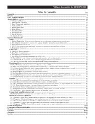
<strong>DFX</strong> ® Table of Contents<br />
Assembly ..........................................................................................................................................................................................2<br />
Batteries ........................................................................................................................................................................................... 4<br />
<strong>DFX</strong> Contents Page<br />
Quick Start ......................................................................................................................................................................... 8<br />
Basic Adjustments ........................................................................................................................................................................ 14<br />
1. Target Volume ...................................................................................................................................................................... 18<br />
2. Audio Threshold .................................................................................................................................................................. 18<br />
3. Tone (Audio Frequency) ...................................................................................................................................................... 19<br />
4. Audio Disc. .......................................................................................................................................................................... 19<br />
5. Silent Search ........................................................................................................................................................................ 20<br />
6. Mixed Mode ......................................................................................................................................................................... 21<br />
7. A.C. Sensitivity .................................................................................................................................................................... 22<br />
8. D.C. Sensitivity .................................................................................................................................................................... 22<br />
9. Backlight Backlight.............................................................................................................................................................................. .............................................................................................................................................................................. 23<br />
10. Viewing Angle ................................................................................................................................................................... 24<br />
Pro Options ................................................................................................................................................................................... 25<br />
Audio .......................................................................................................................................................................................... 27<br />
1. Ratchet Pinpointing ............................................................................................................................................................. 27<br />
2. S.A.T. Speed ........................................................................................................................................................................ 27<br />
3. Tone I.D. .............................................................................................................................................................................. 28<br />
4. V.C.O. .................................................................................................................................................................................. 28<br />
5. Modulation ........................................................................................................................................................................... 28<br />
G.E.B./Trac ............................................................................................................................................................................. 29<br />
6. AutoTrac ® ............................................................................................................................................................................. 29<br />
7. Trac View ............................................................................................................................................................................. 29<br />
8. Trac Speed ........................................................................................................................................................................... 30<br />
9. Trac Offset ........................................................................................................................................................................... 31<br />
10. Trac Inhibit ......................................................................................................................................................................... 31<br />
11. Coarse G.E.B. .................................................................................................................................................................... 32<br />
12. Fine G.E.B. ........................................................................................................................................................................ 33<br />
Discrimination .......................................................................................................................................................................... 34<br />
13. Disc. Edit ...................................................................................................................................................................... 34-35<br />
14. Block Edit ..........................................................................................................................................................................<br />
36<br />
15-16. Learn Accept/Reject .....................................................................................................................................................<br />
37<br />
17. Recovery Speed ................................................................................................................................................................. 38<br />
18. Bottlecap Reject Reject................................................................................................................................................................. ................................................................................................................................................................. 39<br />
19. Hot Rock Reject Reject................................................................................................................................................................. ................................................................................................................................................................. 40<br />
20. Sweep Speed ...................................................................................................................................................................... 41<br />
21. Ground Filtering ................................................................................................................................................................ 42<br />
Display ....................................................................................................................................................................................... 43<br />
22. Visual Disc. ........................................................................................................................................................................ 43<br />
23. Icons ................................................................................................................................................................................... 43<br />
24. V.D.I. Sensitivity ................................................................................................................................................................ 44<br />
25. D.C. Phase ......................................................................................................................................................................... 45<br />
26. Accumulate ........................................................................................................................................................................ 46<br />
27. Average .............................................................................................................................................................................. 46<br />
28. Fade .................................................................................................................................................................................... 47<br />
Preamp Gain ............................................................................................................................................................................. 48<br />
29. Preamp Gain ...................................................................................................................................................................... 48<br />
Multi Frequency Method ......................................................................................................................................................... 49<br />
30. 2 Frequency (Best Data) .................................................................................................................................................... 49<br />
31. 2 Frequency (Correlate) ..................................................................................................................................................... 49<br />
32. V.D.I. Normalization .......................................................................................................................................................... 50<br />
33. 1 Frequency (3 kHz) .......................................................................................................................................................... 50<br />
34. 1 Frequency (15 kHz) ........................................................................................................................................................ 50<br />
EEPROM Programs ................................................................................................................................................................ 51-52<br />
Program Settings Chart .......................................................................................................................................................... 53-54<br />
Glossary ......................................................................................................................................................................................... 55<br />
Warranty ................................................................................................................................................................................... 56-57<br />
Service .......................................................................................................................................................................................... 58<br />
Warranty(UK) .......................................................................................................................................................................... 59-60<br />
1
Chapter 1 <strong>DFX</strong><br />
Assembly<br />
Assembly<br />
Assembly<br />
2<br />
CLEVIS<br />
LOWER<br />
CAMLOCKS<br />
WASHERS BETWEEN<br />
EACH LOOP<br />
EAR & CLEVIS<br />
Trigger behind display activates<br />
depth reading and<br />
pinpoint mode.<br />
LOOP<br />
CABLE<br />
“S” ROD<br />
LOOP OR SEARCH<br />
COIL<br />
CABLE RETAINERS<br />
LOOP CONNECTOR<br />
Remove decal paper from the two rubber<br />
bumpers. Install on the bottom of the control<br />
box, one in each of the front corners (shown<br />
below by "X"). Press in place and hold fi rmly<br />
for a few seconds then release.<br />
COIN PROGRAM<br />
SQUEEZE & RELEASE TRIGGER<br />
AFTER BATT. CHECK.<br />
SCROLL OPTIONS<br />
ATER BATT. CHECK USE<br />
TO SCROLL CURRENT SETTINGS<br />
OR MAKE ADJUSTMENTS<br />
AIR/GND BALANCE<br />
IN SEARCH MODE PRESS<br />
TO RE-AIR/GND BALANCE<br />
GROUND BALANCE ONLY<br />
WHILE SEARCHING HOLD THE<br />
TRIGGER AND PRESS<br />
BATTERY CHECK<br />
WHILE SEARCHING, HOLD THE<br />
TRIGGER AND PRESS<br />
"HOT KEY" SHORTCUTS<br />
REVERSE DISPLAY<br />
WHILE SEARCHING. HOLD<br />
THE TRIGGER AND PRESS<br />
PRESS FOR<br />
LIGHT/DARK BACKGROUND.<br />
RELEASE TRIGGER<br />
BACKLIGHT<br />
IN SEARCH MODE, HOLD THE<br />
TRIGGER AND PRESS<br />
RELEASE TRIGGER<br />
PUSH<br />
VIEW ANGLE<br />
WHILE SEARCHING HOLD<br />
THE TRIGGER AND PRESS<br />
RELEASE TRIGGER<br />
PUSH<br />
BOTTOM OF<br />
CONTROL BOX<br />
CONTROL BOX<br />
Twist and insert each end of<br />
handle (provided) through<br />
top of shipping carton into<br />
second fl ap.<br />
(CARRY CARTON)<br />
DISPLAY<br />
1/ PRESET PROGRAMS<br />
2/ BASIC ADJUSTMENTS<br />
3/ PRO OPTIONS<br />
4/ TARGET ID NUMBERS<br />
5/ TARGET ID ICONS<br />
6/ TARGET ID SIGNAGRAPH ®<br />
7/ BATTERY STRENGTH<br />
TOUCH PADS<br />
SELECT PROGRAMS<br />
ADJUST CONTROLS<br />
ELBOW<br />
CUP<br />
STRAP<br />
BATTERY<br />
COMPARTMENT<br />
DOOR<br />
ELBOW CUP<br />
FOAM PADS<br />
INSIDE ELBOW<br />
CUP<br />
HEADPHONE<br />
JACK<br />
BATTERY<br />
COMPARTMENT<br />
LATCHES
Assembly Instructions<br />
1. Remove all parts from shipping carton and<br />
check the assembly page to make sure all parts are<br />
present.<br />
2. There are rubber washers between clevis/lower<br />
rod and loop ears. Use only nonmetallic washers,<br />
fi ber bolt, and thumbnut to secure loop/search<br />
coil to clevis/lower rod.<br />
3. Unlock "S" rod camlock and insert clevis/lower<br />
rod into curved "S" rod so that stainless steel<br />
spring clip buttons line up and lock into one of<br />
the adjustment holes in the curved "S" rod. Turn<br />
camlock to secure. The second or third adjustment<br />
holes are suitable for average size adults. Individuals<br />
6' or taller should use the fully extended position.<br />
Individuals well over 6' tall should purchase<br />
the optional Tall Man Rod.<br />
4. Unravel loop cable and wind the cable around<br />
the clevis and rod assembly, fi rst revolution over<br />
the top of the rod. Wind cable all the way to the<br />
top of the curved "S" rod, about fi ve revolutions.<br />
Use the black cable retainers, one near the loop,<br />
and one near the top of the curved "S" rod, to hold<br />
the loop cable in place.<br />
5. Unlock control box rod camlock and insert<br />
curved "S" rod so that stainless steel spring clip<br />
buttons line up and lock into the rod on top of the<br />
control box. The "S" rod is designed to curve up<br />
toward the display. However, those who prefer to<br />
sweep the loop close to their feet may desire to<br />
assemble the "S" rod to curve down toward the<br />
ground. Turn camlock to secure. Plug loop connector<br />
into control box, screw lock ring to secure.<br />
6. Grip the instrument by the handle, with your<br />
arm in the elbow cup with strap secure, and sweep<br />
the loop/search coil over the fl oor. If the instrument<br />
fi t feels uncomfortable, adjust the elbow cup<br />
by removing and repositioning the bolt/thumbnut<br />
and installing in one of the optional positions. If<br />
necessary, readjust clevis/lower rod length with the<br />
spring clip buttons so that the search coil can be<br />
held near the fl oor without requiring stooping over.<br />
Chapter 1 <strong>DFX</strong> Assembly<br />
7. Remove the protective paper from the two black<br />
elbow cup foam pads. Carefully align pads on the<br />
inside of the elbow cup, one on each side of the<br />
center rod, and press fi rmly into place.<br />
8. Adjust the elbow cup strap so that it is loose<br />
enough for you to slide your arm in and out without<br />
loosening each time you want to set the detector<br />
down. The elbow cup strap provides extra<br />
leverage and control. However, some prefer not to<br />
use it.<br />
9. Install battery as described in the next section,<br />
decal facing down, with plastic tab and steel contacts<br />
facing toward inside of battery compartment.<br />
10. It should be noted at this point that the detector<br />
may not work as expected indoors due to the high<br />
degree of metals used in modern construction. It<br />
is best to tune and practice out-of-doors to ensure<br />
stable, predictable results. Additionally, freshlyburied<br />
targets will not produce the normal depth<br />
and discrimination results of targets that have been<br />
naturally lost and settled in the ground. Due to the<br />
abnormality caused by digging a hole in the ground<br />
matrix, and the sophistication of the ground rejection<br />
circuitry, it may take a number of years for<br />
freshly-buried targets to respond at true depths and<br />
discrimination accuracy. The best way to determine<br />
true detection depth is in real search conditions.<br />
11. Your <strong>DFX</strong> is designed to automatically turn<br />
itself OFF if the trigger on the grip (or another<br />
control) “is not used” for a period of 10-15<br />
minutes. This protects the battery from damage<br />
in case of an accidental turn on during travel or<br />
storage. Normally something noteworthy of at least<br />
pinpointing/depth reading (keeping the detector<br />
operating) is encountered during each 10 minutes<br />
of search. If searching an unusually area, free<br />
of concentrations of metal, the <strong>DFX</strong> will make<br />
a specifi c bleep upon turn off. Simply press ON<br />
and squeeze and release the trigger on the grip<br />
to resume searching. So long as a good battery<br />
remains, the <strong>DFX</strong> returns to the exact settings prior<br />
to turning itself off.<br />
3
Chapter 2 <strong>DFX</strong><br />
Batteries<br />
Batteries<br />
4<br />
ARROW DOWN<br />
When the instrument is turned on the battery voltage<br />
will momentarily appear after the opening<br />
display. The detector will then continue to the<br />
MAIN MENU. To recheck the battery voltage during<br />
operation, squeeze and hold the TRIGGER and<br />
press the ARROW DOWN control.<br />
TRIGGER<br />
UNDER<br />
DISPLAY POD<br />
Standard Battery Holder<br />
BLUE DECAL<br />
1. The standard battery holder (blue decal) holds<br />
eight “AA” cell batteries. Alkalines are recommended<br />
for use with this battery holder.<br />
2. Non-alkaline batteries can be used in this holder.<br />
When non-alkalines or rechargeable “AA”<br />
cells are used, detecting time (before replacement/<br />
recharge) may be reduced.<br />
3. "LOW BAT" will automatically appear on the<br />
display when the batteries become too low to properly<br />
operate the detector.<br />
4. The battery compartment opens by gently pulling<br />
down on the front of each of the two latches<br />
(on the bottom of the control box) releasing the<br />
catch and hinging open the door.<br />
The non-rechargeable battery holder can use many<br />
different types of batteries, including rechargeable.<br />
This holder is designed for standard size penlight<br />
"AA" batteries which should be 50 mm ± .10mm.<br />
Battery lengths shorter than this will likely cause<br />
problems with this power supply.
Using the<br />
Standard Battery Holder<br />
1. Slide open the battery holder lid (decal side of<br />
battery holder) by applying gentle upward<br />
pressure on the tab of the door so that it unlocks.<br />
Slide the door away from the battery box<br />
exposing the cell positions.<br />
2. Remove any old cells from the holder. Note the<br />
(+) and (-) positions of each cell and the (+)<br />
and (-) for each position marked inside the cell tray.<br />
Install new “AA” cells noting carefully the correct<br />
(+) and (-) positions.<br />
If the cells are installed incorrectly, the detector<br />
may require service by an Authorized<br />
Service Center.<br />
3. Slide the door closed so that it snaps securely.<br />
4. Insert the battery holder into the detector so that<br />
the decal is facing down, with the battery<br />
holder door tab and metal contact points facing<br />
toward the inside of the battery compartment.<br />
Close the battery compartment door and secure<br />
the two latches on the bottom of the case. Hook<br />
the front of each latch fi rst, then press down on the<br />
rear.<br />
BATTERY<br />
COMPARTMENT DOOR<br />
BATTERY HOLDER<br />
WITH DECAL SIDE DOWN AND<br />
METAL CONTACTS TO FRONT<br />
Chapter 2 <strong>DFX</strong> Batteries<br />
Rechargeable Battery<br />
GREEN<br />
DECAL<br />
CHARGER PLUG<br />
BATTERY<br />
CHARGER<br />
QUICK<br />
CHARGE<br />
OR OVER-<br />
NIGHT<br />
SWITCH<br />
(U.S.A. ONLY)<br />
A rechargeable battery (green decal) is provided<br />
with your instrument. This battery can be recharged<br />
hundreds of times as long as the battery hasn't been<br />
stored for extended periods of time or overcharged.<br />
Full charge can be achieved anytime during the<br />
discharge cycle. When using the QUICK charge<br />
setting (U.S.A. only) use the Charging Hours chart<br />
on the following page for charge time. A full charge<br />
will last ten to fi fteen hours of normal use.<br />
Battery life will vary with temperature, the number<br />
of targets found, and the exact settings used. Six<br />
hours is not unusual for extreme high performance<br />
settings, backlight use, or for batteries that have<br />
experienced extensive use.<br />
(QUICK CHARGE is for USA ONLY. It is not<br />
available on 220-240 volt.) Your charger has a<br />
switch on it that selects the QUICK charge, or<br />
OVERNIGHT charge options. Always check the<br />
position of this switch prior to charging. Always<br />
follow the charge hours on the chart on the following<br />
page when the QUICK charge setting is used.<br />
Overcharging with the QUICK charge setting will<br />
damage the system.<br />
5
Chapter 2 <strong>DFX</strong> Batteries<br />
Charging<br />
1. There is no harm charging<br />
overnight using the<br />
OVERNIGHT charge<br />
setting regardless of the<br />
battery's current condition.<br />
However, before charging<br />
with the QUICK charge<br />
setting, determine battery<br />
condition by inserting battery<br />
into the instrument and<br />
turning the instrument ON.<br />
If the instrument will not<br />
turn ON, or if voltage tests<br />
eight volts or below, charge<br />
fi ve hours with the QUICK<br />
charge. If the battery voltage tests any other voltage,<br />
refer to the Charging Hours chart above for<br />
proper QUICK charge time.<br />
2. To charge, insert the charger plug into the battery<br />
pack jack, located near the plastic tab and<br />
metal contact points.<br />
3. Plug the charger into a standard wall outlet. (110<br />
volts for USA models).<br />
4. Again, the QUICK charge setting uses the above<br />
chart for a specifi c charge time. OVERNIGHT is<br />
designed to charge the battery in as little as fourteen<br />
hours. However, no harm will come to the system<br />
leaving it charging for several days.<br />
5. It is normal for the battery and charger to get<br />
warm during use. However, if either the battery or<br />
the charger gets too hot to hold or deforms due to<br />
the heat, discontinue use and return for testing.<br />
6<br />
6. The battery will lose its charge during storage.<br />
If stored inserted in your instrument, this loss<br />
will be more noteworthy. It is recommended that<br />
the battery be removed from the instrument during<br />
periods of storage. It is not advisable to store<br />
rechargeable batteries for long periods of time<br />
without use. If however, storage is necessary, store<br />
without a charge (discharged).<br />
7. Do not discharge the battery in devices other<br />
than your metal detector. Unnecessary discharging<br />
and/or an absolute discharge will reduce battery<br />
life and may damage the battery. Unlike older rechargeable<br />
battery designs, the rechargeable battery<br />
provided with your detector can be recharged at any<br />
time. Regardless of whether or not it already has a<br />
partial charge, memory will not occur.<br />
8. <strong>White's</strong> has provided the leading edge of rechargeable<br />
battery technology with your instrument.<br />
Disregard all advice which confl icts with the<br />
above recommendations. Care for batteries provided<br />
by other manufacturers, or with other <strong>White's</strong><br />
models, may vary.
Battery Life & Memory<br />
Volatile memory temporarily holds any program<br />
changes or settings not yet saved in a Custom Program.<br />
Short-term or volatile memory is retained so<br />
long as a good battery remains in the detector. To<br />
recover volatile memory immediately squeeze and<br />
release the TRIGGER once the detector is turned<br />
ON. If the battery is removed all volatile memory<br />
is lost. Long-term memory (programs saved in<br />
Custom Programs) is automatically saved for up to<br />
ten years regardless of whether a battery is in the<br />
detector or not.<br />
When using fresh batteries, the voltage will initially<br />
check somewhere in the 10 to 14 volt area. Unlike<br />
standard batteries, the rechargeable battery voltage<br />
will quickly drop to between 9 and 10 volts and<br />
plateau there for most of its life. Once the rechargeable<br />
battery voltage drops below this plateau, it will<br />
quickly drop below a usable voltage level (eight<br />
volts) and thus require a recharge. Low Battery will<br />
automatically appear on the display when the battery<br />
reaches eight volts.<br />
Like a personal computer, there are times (such as<br />
low battery conditions) when the microprocessor of<br />
a metal detector becomes out of sequence with the<br />
rest of the circuitry. This is often noted by peculiarities<br />
in the nondiscrimination or pinpointing (TRIG-<br />
GER squeezed) modes. Symptoms may be blaring<br />
or silent non-discriminate or pinpoint modes, depth<br />
indication inaccuracies or general abnormal operation.<br />
To correct such diffi culties "re-boot" by:<br />
1. Install a good battery.<br />
2. Turn ON wait for MAIN MENU to appear.<br />
3. Open battery door and remove battery while<br />
detector is still ON.<br />
4. Wait one minute, reinstall battery, turn<br />
detector ON, and check for proper function.<br />
Chapter 2 <strong>DFX</strong> Batteries<br />
Use of maximum backlight may reduce battery life<br />
by up to 50%, depending on battery type.<br />
Rechargeable batteries gradually deteriorate. As<br />
they age they do not provide the life-per-charge<br />
they did when new. This is expected, and not<br />
grounds for replacement under warranty. Additionally,<br />
a damaged initial cell, which is caused by overcharging<br />
with the QUICK option, is not replaced<br />
under warranty. Only cell failure through normal<br />
use, or a defect due to a problem with a <strong>White's</strong><br />
warranted <strong>DFX</strong> charger, is covered.<br />
7
Chapter 3 <strong>DFX</strong> Quick Start<br />
<strong>DFX</strong> Quick Start<br />
TRIGGER<br />
UNDER<br />
DISPLAY POD<br />
CENTER<br />
POSITION<br />
8<br />
1<br />
3<br />
4<br />
5<br />
6<br />
7<br />
8<br />
2<br />
(press ENTER)<br />
(press ENTER)<br />
(press ENTER)<br />
(press ENTER)<br />
(LIVE SEARCH SCREEN)<br />
<strong>DFX</strong> Quick Start Instructions<br />
After you have assembled the <strong>DFX</strong> and inserted the<br />
battery pack, follow these simple steps to start<br />
treasure hunting!<br />
1<br />
2<br />
3<br />
4<br />
5<br />
6<br />
7<br />
8<br />
With the TRIGGER in the center position,<br />
press the ON/OFF control and an automatic<br />
sequence will begin.<br />
The display will momentarily show an<br />
opening screen which lists the software<br />
version.<br />
The display then shows a battery check<br />
screen.<br />
The last automatic display screen to appear<br />
is the MAIN MENU. Press the ENTER<br />
control. ("BEEP")<br />
The Preset Program COINS will appear on<br />
the MENU. Press ENTER . ("BEEP")<br />
You will be prompted to raise the search<br />
coil (loop) to waist level. Press ENTER .<br />
This air balances the <strong>DFX</strong> . ("BEEP")<br />
Next, the ground balance prompt appears<br />
asking you to lower the search coil (loop) to<br />
the ground. Press ENTER. Ground mineralization<br />
will be balanced out. ("BEEP")<br />
The last screen will be the live search<br />
screen. You will hear the THRESHOLD<br />
"hum". Sweep the search coil over the<br />
ground and listen for a solid repeatable/consistent<br />
beep, then look at the display. The<br />
icons tell what likely coin lies below. V.D.I.<br />
number/chart on top of control box and SignaGraph®<br />
provide greater detail. Squeeze<br />
the trigger for pinpointing and depth and it's<br />
time to dig!
Search Fundamentals<br />
The loop/search coil must be in motion (sweeping<br />
from side-to-side) for this instrument to<br />
respond to metal. Practice a smooth sweep of<br />
the loop from side-to-side keeping the loop close<br />
to the ground throughout the swing. Each pass of<br />
the loop should take approximately two seconds<br />
from right to left, two seconds to return from left<br />
to right.<br />
Walk forward slowly. Take small steps no greater<br />
than half normal strides. Make sure each pass of<br />
the loop overlaps the last by at least half the length<br />
of the loop. Do not lift the loop at the end of each<br />
swing. Keep it close to the ground at all times.<br />
To become comfortable with sweeping the loop<br />
takes some practice. Try to loosen up and fi nd a<br />
comfortable grip on the handle. Premature fatigue<br />
may result from gripping the handle too tightly, improperly<br />
adjusted rod or elbow support, and limited<br />
body movement. Hold the handle loosely. Adjust<br />
the rod and elbow support for comfort and keep the<br />
elbow strap loose. Use your arm, shoulder and even<br />
your back a little to allow a smooth even sweep of<br />
the loop.<br />
Now that you're sweeping the loop smoothly over<br />
the ground, you will notice that the detector starts<br />
making sounds (beeps). Not all sounds are good<br />
targets; some trash targets also make the detector<br />
beep.<br />
Chapter 3 <strong>DFX</strong> Quick Start<br />
As the loop is swept over the ground, ignore the<br />
display and concentrate on the sounds the detector<br />
makes.<br />
As the loop is passed over metal that is likely trash,<br />
the sound will be inconsistent. Trash targets typically<br />
produce a shorter, sputter-type sound, that<br />
is often broken or double in nature. Place a steelpop<br />
bottlecap on the ground. Pass the loop over it<br />
several times to become familiar with this sound at<br />
different loop sweep speeds. Note that an aluminum<br />
twist-off bottlecap cannot be used as it is a different<br />
type of target. Also note that very old rusty bottle<br />
caps may start reading as quarters due to the elimination<br />
of the iron alloy through deterioration. Once<br />
familiar with the sound typical bottle caps produce,<br />
an operator may pass over such targets and continue<br />
searching without consulting the display information,<br />
saving more time for evaluating possible good<br />
targets.<br />
As the loop passes over metal that is likely a good<br />
target, a more consistent and smooth sound will be<br />
heard. A good target typically produces a longer,<br />
more solid sound. Place a quarter on the ground<br />
and sweep the loop over it several times to become<br />
familiar with the sound of a good target.<br />
Why Air/Ground Balance?<br />
When the display prompts you to AIR BALANCE<br />
by holding the loop at waist level and press EN-<br />
TER. The <strong>DFX</strong> 's circuits are being prepared for<br />
ground balancing by measuring temperature and<br />
other variables that affect electronic circuits. The<br />
<strong>DFX</strong> "beeps" and you lower the search coil to the<br />
distance above the ground that you will be searching.<br />
Press ENTER to have the <strong>DFX</strong> "cancel/track<br />
out" or GROUND BALANCE the ground mineralization.<br />
The <strong>DFX</strong> then automatically "tracks<br />
out" the varying mineralization as you continue to<br />
9
Chapter 3 <strong>DFX</strong> Quick Start<br />
Live Search Screen - what is it telling me?<br />
VISUAL<br />
DISCRIMINATION<br />
INDICATION-V.D.I. NUMBER<br />
("TARGET REFERENCE NUMBER")<br />
10<br />
POSSIBLE TARGET IDENTITIES<br />
("ICONS")<br />
SIGNAGRAPH BAR-<br />
GRAPH<br />
MULTIFREQUENCY<br />
METHOD<br />
CURRENTLY IN<br />
USE<br />
1. V.D.I. Visual Discrimination Indication<br />
("target reference number")<br />
In the upper left hand-side of the display there is<br />
a V.D.I. number that corresponds to the V.D.I.<br />
SCALE painted on the top right-hand side of the<br />
control box. It also corresponds to the Discriminate<br />
Edit feature allowing you to reject or accept targets<br />
based on their V.D.I. reference number. There are<br />
"+" numbers for nonferrous (not of iron) targets,<br />
and "-" numbers for ferrous (iron) targets. Rejected<br />
V.D.I. numbers may not appear if the VISUAL<br />
DISCRIMINATION feature is ON. Reasonably<br />
consistent V.D.I. reference numbers (± fi ve digits),<br />
in a desirable area of the chart is a vote for digging<br />
the target.<br />
2. Possible Target Identities ("Probable or most<br />
likely target")<br />
To the right of the V.D.I. number, possible target<br />
identities will be represented graphically. These<br />
graphics are called ICONS. A fairly consistent indication<br />
of a desirable target is another vote to dig<br />
the target. One or two possible target icons may<br />
appear. There is signifi cance to which icon appears<br />
fi rst. The fi rst target to appear is always the most<br />
likely, the second is another possibility, slightly less<br />
likely than the fi rst.<br />
3. SignaGraph ®<br />
The SignaGraph ® at the bottom of the display<br />
provides a fi nal vote as to whether or not the target<br />
should be dug.<br />
A. Sweep the loop over the target several times<br />
and look at the SignaGraph ® . The SignaGraph®<br />
automatically clears itself (FADE RATE) so that it<br />
doesn't fi ll the screen with information from past<br />
loop sweeps. An operator has limited time to look<br />
at the SignaGraph ® . If you want to look at the<br />
information again, sweep the loop over the target<br />
several more times. The fading of the SignaGraph ®<br />
information can be slowed or speeded (FADE<br />
RATE) to operator preference. This is completed<br />
in the PRO OPTIONS under DISPLAY. Automatic<br />
AVERAGING and/or ACCUMULATING of SignaGraph<br />
® information is also available (See PRO<br />
OPTIONS).<br />
B. Valuable targets will show up on the positive<br />
side of the graph. The positive area of the chart is<br />
the section located to the right of the zero.<br />
C. Look for consistency. In ideal conditions, coins<br />
and jewelry produce one or two bars to the right of<br />
zero. Trash produces several bars, sometimes on<br />
both sides of zero.<br />
D. In less than ideal conditions, coins may produce<br />
a wider pattern of bars. Most trash targets produce a<br />
recognizably different pattern than valuable targets.<br />
E. One of the most visual benefi ts of the Signa-<br />
Graph ® is the ability to show a smear pattern<br />
on iron targets that often fool the other methods<br />
of identifi cation. An iron target will likely show<br />
defi nite bars on both the negative and positive sides<br />
of the SignaGraph ® , often smearing all the way<br />
across the entire chart. Valuable targets should not<br />
produce such obviously wide patterns. In very bad<br />
ground conditions, a good target may have a few<br />
small bar segments in the negative area due to mineralization.<br />
However, the pattern will show mostly<br />
positive bars, in a fairly narrow tall group.
Live Search Screen Samples<br />
Nickel, or<br />
possible ring.<br />
Sometimes a<br />
small (or half)<br />
pull tab will<br />
produce this<br />
indication<br />
Quarter. Could<br />
be a worn half,<br />
or large silver<br />
jewelry.<br />
IRON. REJECT<br />
targets will<br />
produce only a<br />
SignaGraph ® if<br />
VISUAL DISC.<br />
is ON<br />
IRON. -18<br />
ACCEPTED or<br />
VISUAL DISC.<br />
OFF.<br />
Pull tab. Possible<br />
ring. +30<br />
ACCEPTED or<br />
VISUAL DISC.<br />
OFF.<br />
Chapter 3 <strong>DFX</strong> Quick Start<br />
Penny or a<br />
dime. If the<br />
screw cap and<br />
penny ICON<br />
are displayed,<br />
the target<br />
could be an<br />
Indian Head or<br />
zinc penny.<br />
Dollar. Large<br />
non-iron can<br />
also produce<br />
this indication<br />
(large brass jar<br />
lids).<br />
IRON. +95<br />
ACCEPTED or<br />
VISUAL DISC.<br />
OFF<br />
Foil. Possible<br />
ring. +10 AC-<br />
CEPTED or<br />
VISUAL DISC.<br />
OFF.<br />
Ring. Possible<br />
pull tab. +48<br />
ACCEPTED or<br />
VISUAL DISC.<br />
OFF.<br />
11
Chapter 3 <strong>DFX</strong> Quick Start<br />
SQUEEZE TRIGGER<br />
DEPTH SCREEN<br />
DISPLAYED WHEN<br />
THE TRIGGER<br />
IS SQUEEZED<br />
12<br />
"X" THE LOOP TO "PINPOINT"<br />
THE TARGET<br />
Advanced Pinpointing Techniques<br />
1. Targets that are near the surface, because<br />
they give a wider response, are harder to<br />
pinpoint than deep targets. If the trigger is held<br />
and the loop swept over the area, you may<br />
note a shallow depth indication. Lifting the loop<br />
slightly above the ground, releasing and resqueezing<br />
the TRIGGER and again "X" ing the<br />
target will aid pinpointing.<br />
2. In the Basic Adjustments, DC Sensitivity<br />
(non-motion) directly controls the pinpointing<br />
mode. Lower DC Sensitivity settings pinpoint<br />
shallow targets better.<br />
3. In the PRO OPTIONS under AUDIO, V.C.O.<br />
(Voltage Controlled Oscillator) signifi cantly aids<br />
pinpointing.<br />
4. The depth reading has two indication bars.<br />
The top bar shows the current distance from<br />
the target, and the bottom bar shows a memory<br />
of the strongest reading. These two bars will be<br />
even with each other when the loop is directly<br />
over the center of the target.<br />
Pinpointing the Target<br />
Once the decision has been made to dig, move the<br />
loop off to one side of the target area, squeeze and<br />
hold the TRIGGER on the handle, and "X" the loop<br />
over the spot where you believe the target to be.<br />
Note that the TRIGGER also has a locked forward<br />
position that accomplishes the same thing as<br />
squeezing and holding it.<br />
While the TRIGGER is being held, the loop doesn't<br />
need to be moving to detect the target. The loop<br />
may be moved slowly over the area. The display<br />
will indicate depth in inches and will also show<br />
the strongest reading to aid in pinpointing exactly<br />
where to dig. The shallowest reading on the depth<br />
display, the loudest sound coming from the speaker,<br />
and the two bars lining up with each other, indicate<br />
the center of the target. Don't forget to "X" the<br />
target as pinpointing cannot be accurate unless the<br />
target is swept from at least two different directions.<br />
Once pinpointing is complete, release the TRIG-<br />
GER, or return it to the center position.<br />
Pinpointing takes practice. The standard loop provided<br />
with the <strong>DFX</strong> is a high-powered, 12 inch<br />
design. This harmonically tuned loop's strongest<br />
traits are in the detection depth and ground coverage<br />
areas. If pinpointing becomes diffi cult or critical<br />
refer to the Advanced Pinpointing Techniques<br />
on this page.
Ready to Dig<br />
Permission - Prior to searching and digging you<br />
must have permission to search private property,<br />
from the owner or caretaker.<br />
Laws - Know the laws that apply to the area you<br />
are going to search. Laws vary a great deal with the<br />
City, County, State, and Country, regarding the use<br />
of metal detectors. Be respectful of private property,<br />
public property, and the laws which govern the<br />
use of metal detectors.<br />
Tools - Care must be taken to dig in a way that is<br />
friendly to the landscape. Tools and methods vary a<br />
great deal with the area, season, and types of target<br />
you are recovering. Check with your dealer for<br />
recommended tools and methods for your area.<br />
Trash - When searching, remove all trash you come<br />
across. This not only makes your future searches of<br />
the area more productive; it promotes the hobby of<br />
metal detecting.<br />
Get Involved - Your dealer knows of metal detecting<br />
clubs and organizations which promote and<br />
protect the hobby. A club is a great way to not only<br />
learn good detecting habits, but to gain permission<br />
to search areas as a group as well as have organized<br />
competition hunts.<br />
Chapter 3 <strong>DFX</strong> Quick Start<br />
Factory Preset Programs<br />
Reached from the MAIN MENU, the factory PRE-<br />
SET PROGRAMS give a quick start for:<br />
Coins: general purpose settings, discriminates (rejects)<br />
most common junk items like nails, foil, pull<br />
tabs, and hot rocks; and responds to most coins and<br />
large jewelry. Use in lawns, parks, and playgrounds<br />
where lots of trash rejection is desired.<br />
Coin & Jewelry: less discrimination (less trash<br />
rejection), desirable because of the high degree of<br />
variance found in jewelry alloys. More digging<br />
required. Good program for lawns, parks, and playgrounds.<br />
Use screen in conjunction with sound.<br />
Jewelry & Beach: similar to Coin & Jewelry, but<br />
settings are optimized for salt water.<br />
Relic: even less discrimination than Coin & Jewelry<br />
or Jewelry & Beach, all types of metals except<br />
small iron items like nails, and some stainless steel.<br />
Brass, lead, aluminum, as well as copper, silver,<br />
and gold all respond solidly. Ferrous (iron), such<br />
as large nails, weapons, and cannon ball fragments<br />
will also respond . Suitable for all signifi cant targets<br />
and separates ferrous/nonferrous by display indications.<br />
Prospecting: NO AUDIO DISCRIMINATION. All<br />
metals respond with beep. But V.D.I. numbers show<br />
only for metals that could be gold. Dig only V.D.I.<br />
number (possibility gold) targets and avoid iron.<br />
Targets which cause an audio response, without<br />
causing a V.D.I. number to appear on the display,<br />
are not likely to be gold nuggets. Although highfrequency<br />
gold-shooting detectors will respond<br />
better, this mode will offer good results for the occasional<br />
nugget hunter by responding to nuggets in<br />
the six-grain and heavier category.<br />
13
Chapter 4 <strong>DFX</strong> Basic Adjustments<br />
Basic Adjustments<br />
Basic Adjustments - what do they do?<br />
1. TARGET VOLUME - How loud a target beeps when detected.<br />
2. AUDIO THRESHOLD - The slight hum or background sound heard continuously during searching.<br />
3. TONE (AUDIO FREQUENCY) - Selects the frequency or pitch of sound the detector produces.<br />
4. AUDIO DISCRIMINATION - The ability to reject trash, different sounds for different types of targets.<br />
5. SILENT SEARCH - The ability to operate without the threshold or background hum.<br />
6. MIXED-MODE - DC non-discriminate mode, working simultaneously with AC discrimination mode.<br />
7. A.C. SENSITIVITY - Degree instrument is responsive to signals in the discriminate (motion) modes.<br />
8. D.C. SENSITIVITY - Degree instrument is responsive to signals in non-discriminate (non-motion)<br />
modes.<br />
9. BACKLIGHT - Used in dark conditions to light the display improving visibility.<br />
10. VIEWING ANGLE - Adjusts the display for low or high temperature visibility.<br />
14<br />
ADJUSTMENT<br />
EXAMPLE:<br />
RECTANGLE AROUND<br />
THE TITLE MOVES TO<br />
THE SETTING<br />
(press ENTER)<br />
(press ENTER)<br />
USE ARROW KEYS TO<br />
ADJUST THE SETTING<br />
UP OR DOWN<br />
TIP - To quickly increase to<br />
maximum, hold ENTER and<br />
press ARROW up. To quickly<br />
decrease to minimum, hold<br />
the ENTER and press AR-<br />
ROW down.<br />
ADJUSTMENT<br />
EXAMPLE:<br />
Basics of Basic Adjustment<br />
After you have had some fi eld experience, you may<br />
want to make some changes to the basic settings<br />
of your detector. From the search mode press<br />
MENU. At this point, the MAIN MENU will appear<br />
on the display. Use the ARROW controls to<br />
move the pointer to Basic Adjustments, and then<br />
press ENTER. You may now use the ARROW<br />
down control to scroll through the Basic Adjustments.<br />
Using the fi rst adjustment screen (TARGET VOL-<br />
UME) as an example, the screens with a graphic<br />
control knob require you to fi rst press ENTER<br />
then use the ARROW up and down controls to<br />
adjust. Note: when ENTER is pressed the square<br />
around the title moves to the setting, indicating you<br />
are ready to make adjustments with the ARROW<br />
controls. After adjusting press MENU and use<br />
the ARROW controls to continue viewing/setting<br />
other Basic Adjustments, or squeeze and release the<br />
TRIGGER to begin searching<br />
Adjustment screens with an on/off selection need<br />
only for you to press ENTER to change setting.<br />
Pressing ENTER again changes back to the original<br />
setting.
More Basics<br />
All the MENU items are tied together so that the<br />
ARROW up and down controls scroll through every<br />
adjustment screen. If you continue to press the<br />
ARROW down you can go beyond the last BASIC<br />
ADJUSTMENT (View Angle) and into the PRO<br />
OPTIONS. If the ARROW up control is pressed<br />
after VOLUME, you will be scrolling backwards<br />
through the options starting with the end of the Preset<br />
Programs, then the MAIN MENU, then the end<br />
of the PRO OPTIONS.<br />
An important feature of the ARROW controls; If a<br />
BASIC ADJUSTMENT has been made (for example<br />
Volume) and the trigger has been squeezed and<br />
released to return to a search mode, you can return<br />
to the volume adjustment simply by pressing either<br />
of the ARROW controls. This shortcut returns to<br />
the last adjustment that was made thereby allowing<br />
an operator to switch directly from a search mode<br />
to the adjustment currently being fi ne tuned. This<br />
feature is desirable as you start using BASIC AD-<br />
JUSTMENTS or PRO OPTIONS that are located<br />
further down the menu listings, or any adjustment<br />
that may require some trial and error to fi nd the appropriate<br />
setting.<br />
If care is taken to use a desired adjustment screen<br />
last (just prior to squeezing and releasing the TRIG-<br />
GER for a search mode), Custom Programs can use<br />
this ARROW RETURN feature to allow quick easy<br />
access to the most used feature. Use that feature<br />
(adjustment screen) last, just prior to squeezing and<br />
releasing the TRIGGER for searching. Then during<br />
searching, press either ARROW to return directly to<br />
that adjustment screen.<br />
Chapter 4 <strong>DFX</strong> Basic Adjustments<br />
"Hot Key" Shortcuts<br />
"HOT KEYS" will save time as they allow easy<br />
access, from the search mode, to the most needed<br />
adjustments. They are painted on the bottom of the<br />
control box for fi eld reference. NOTICE: "HOT<br />
KEY" shortcuts will not function from a cold start<br />
(batteries just installed). To function from a cold<br />
start the <strong>DFX</strong> must be turned on and air/ground<br />
balanced in any mode, then turned off. "HOT KEY"<br />
shortcuts will then function.<br />
COIN PROGRAM - Squeeze & release TRIGGER<br />
after automatic battery check.<br />
SCROLL OPTION - After battery check, use AR-<br />
ROWS to scroll all the current settings /menus.<br />
AIR/GROUND BALANCE - In search mode,<br />
press ENTER to re-Air/Ground Balance.<br />
GROUND BALANCE ONLY - While searching,<br />
hold the TRIGGER and press ENTER.<br />
BATTERY CHECK - While searching, hold the<br />
TRIGGER and press ARROW down. Squeeze and<br />
release TRIGGER to return to searching.<br />
REVERSE DISPLAY - While searching, hold<br />
the TRIGGER and press ARROW DOWN. Press<br />
ARROWs for light/dark background. Light or dark<br />
background will not change battery life. It will<br />
make the display easier for some to read, particularly<br />
in certain light conditions. It will work in combination<br />
with backlight. Reversed display is only<br />
accessible through the "HOT KEYS".<br />
BACKLIGHT - In search mode, hold TRIGGER<br />
and press MENU. Release TRIGGER, press<br />
ARROWS to set.<br />
VIEW ANGLE - While searching, hold the TRIG-<br />
GER and press ARROW up. Release TRIGGER,<br />
press ARROWS to set.<br />
15
Chapter 4 <strong>DFX</strong> Basic Adjustments<br />
Custom EEPROM Programs<br />
Saving Basic and Pro Option<br />
adjustments for future use.<br />
Save custom settings in any one of four EEPROM<br />
program positions. They will remain permanently<br />
in the <strong>DFX</strong> memory regardless if the machine<br />
is turned off or the battery removed. Custom EE-<br />
PROM Programs can be changed at any time by<br />
saving new settings over a previously saved custom<br />
program. EEPROM is a special type of computer<br />
memory made for this purpose, (Electrical-Erasable-Programmable-Read-Only-Memory).<br />
16<br />
1 SQUEEZE<br />
TRIGGER<br />
2<br />
3<br />
THEN PUSH<br />
MENU<br />
PRESS ENTER FOR PRESET PROGRAMS<br />
SCROLL DOWN WITH ARROW KEYS<br />
PRESS ENTER<br />
PRESS ENTER<br />
4<br />
USE THE ARROW KEYS TO SCROLL THE<br />
FLASHING SYMBOLS, PRESS ENTER<br />
PRESS MENU<br />
1. 1 Once all of the changes you desire have been<br />
made to any Preset Program or existing Custom<br />
Program, squeeze and release the TRIGGER as if to<br />
search.Then push MENU for MAIN MENU.<br />
2. 2 Use the ARROW controls to select one of the<br />
four Custom Programs then press ENTER.<br />
3. 3<br />
You now must make one of three choices (use the<br />
ARROW controls to make your selection):<br />
A. LOAD will activate a prior custom program<br />
stored in that position. After you have<br />
SAVED or NAMED a program, you can select<br />
LOAD and press ENTER, to use that program.<br />
B. SAVE saves your current settings in that<br />
custom position with either a generic name or<br />
a prior custom name you may have applied.<br />
Selecting SAVE and pressing ENTER saves<br />
the current program.<br />
C. NAME is the preferred method. Select<br />
NAME and press ENTER. You may now use<br />
the ARROW and ENTER controls to name<br />
your custom program. NAME automatically<br />
SAVES, once you have chosen a name and<br />
pressed MENU.
4<br />
4. To NAME, use the ARROW controls to select<br />
the fi rst symbol, number, or letter of the name and<br />
press ENTER. Use the ARROW controls to select<br />
the second symbol, number, or letter of the name,<br />
press ENTER. And so on using up to sixteen digits.<br />
To leave a space, use the ARROWS to select the<br />
point where no symbol or letter appears and press<br />
ENTER. If you make a mistake and press ENTER<br />
when the digit is not as you desire, simply keep<br />
pressing ENTER until that digit is again fl ashing,<br />
then use the ARROWs to select the correct digit and<br />
again press ENTER. It is wise to name the custom<br />
program something that relates to what it is used<br />
for. For example "TRASHY PARKS", "GHOST<br />
TOWN", "NIGHT HUNT", "COMPETITION", etc.<br />
Once the name is fully assembled press MENU.<br />
5. Once you have SAVED and pressed ENTER, or<br />
NAMED and pressed MENU, there are four directions<br />
you can go:<br />
A. Squeeze and release the TRIGGER to con-<br />
tinue searching using your new custom program.<br />
B. Press ENTER, select LOAD and press<br />
ENTER to continue searching using your<br />
new custom program.<br />
C. Press MENU to return to choose or develop a<br />
different program than what you stored.<br />
D. Turn the detector OFF.<br />
6. When the detector is turned back on, regardless<br />
of whether a battery pack was left in the detector or<br />
not, your custom program will be ready for you to<br />
use again and again. Simply select it, press ENTER,<br />
select LOAD, and press ENTER again. Follow the<br />
on-screen instructions for Air/Ground Balance and<br />
then search.<br />
7. If you SAVE or NAME a program, then decide<br />
you no longer want to keep it, you can replace it<br />
with a new program using the same procedure<br />
Chapter 4 <strong>DFX</strong> Basic Adjust-<br />
as described above. The old program can only be<br />
erased when a new program is stored in that position.<br />
8. You can NAME a custom program and at a later<br />
date replace the program while maintaining the<br />
same name. Develop the changes fi rst to any program,<br />
then use the SAVE method which maintains<br />
the old name while storing the new program. To<br />
keep the same program with a new name, fi rst<br />
LOAD that custom program, Air/Ground Balance,<br />
then press MENU and go to that custom position<br />
and press ENTER. Now select NAME and press<br />
ENTER. You can now develop a new name for the<br />
old program.<br />
Other Custom EEPROM<br />
Program Info<br />
Ground Balance - When a Custom Program is<br />
stored, the Ground Balance setting last used with<br />
that program is also stored. This has advantages<br />
particularly for those who manually set the Ground<br />
Balance for speciality applications. The automatic<br />
Air/Ground Balance sequence will always override<br />
manual settings. To access the last Ground Balance<br />
setting used with a Custom Program, fi rst select the<br />
desired Custom Program then press ENTER. Select<br />
LOAD and press ENTER. Do not Air/Ground Balance<br />
as the display suggests, simply squeeze and<br />
release the TRIGGER. The last Ground Balance<br />
setting will then be in use. If an appropriate Air/<br />
Ground setting is not available, the instrument will<br />
automatically require a new Air/Ground Balance.<br />
Return ARROW Key - The last Basic Adjustment<br />
or Pro Option screen used is remembered by your<br />
Custom Program. From the search mode, either<br />
ARROW control will access the last Basic Adjustment<br />
or Pro Option screen used. This allows easy<br />
access to the most used adjustment.<br />
Factory Preloaded EEPROM PROGRAMS are<br />
described on pages 53 and 54.<br />
17
Chapter 4 <strong>DFX</strong> Basic Adjustments<br />
18<br />
Tip - Select the loudest<br />
comfortable level, lower<br />
with headphones, higher<br />
without. Settings from<br />
48 - 63 are available.<br />
Tip - Select the lowest<br />
level you can still hear.<br />
Settings from 0 - 42 are<br />
available<br />
1. Target Volume 48 - 63<br />
How loud a target beeps when detected.<br />
Select TARGET VOLUME with the ARROW<br />
controls and press ENTER. The current volume<br />
level sounds continuously. The number designating<br />
the current level is shown on the right side of the<br />
display. To the left, the graphic knob indicates the<br />
relationship of the current setting to minimum and<br />
maximum levels.<br />
Use the ARROW controls to select the volume level<br />
you desire. Volume level will select the loudest<br />
possible sound a shallow target can produce. High<br />
volume levels will slightly reduce battery life.<br />
Press MENU and use the ARROWS to continue<br />
viewing and/or adjusting Basic Adjustments, or<br />
Squeeze and release TRIGGER to begin searching.<br />
2. Audio Threshold<br />
The slight hum or background tone which is normally<br />
heard continuously during searching.<br />
Select THRESHOLD with the ARROW controls,<br />
and press ENTER . The current threshold level<br />
will sound continuously. The number designating<br />
the current level is shown on the right side of the<br />
display. To the left the graphic knob indicates the<br />
relationship of the current setting to minimum and<br />
maximum levels. Note that the maximum threshold<br />
level (42) is well below the minimum VOLUME<br />
level. Thus with the THRESHOLD at maximum,<br />
and the VOLUME at minimum, the detector will<br />
still respond to metal. Use the ARROW control to<br />
select the threshold level you desire. High threshold<br />
levels will slightly reduce battery life.<br />
Press MENU.
Tip - If you have trouble<br />
hearing high frequencies<br />
select low TONE levels<br />
(low numbers). If you<br />
have trouble hearing low<br />
frequencies, select high<br />
TONE levels (high numbers).<br />
Settings from 0-255<br />
are available.<br />
Tip - Use AUDIO DISC<br />
ON for trash rejection,<br />
AUDIO DISC OFF for<br />
detection of all types of<br />
metals.<br />
Chapter 4 <strong>DFX</strong> Basic Adjustments<br />
3. Tone (Audio Frequency)<br />
Selects the frequency or pitch of the sound the<br />
detector produces.<br />
Select TONE (AUDIO FREQ.) with the ARROW<br />
controls and press ENTER. The current TONE<br />
will sound continuously. The number designating<br />
the current level is shown on the right side of<br />
the display. To the left, the graphic knob indicates<br />
the relationship of the current setting to minimum<br />
and maximum levels. Low frequencies, from<br />
about 100 down, begin to pulse. Select an audio<br />
frequency that you can hear comfortably and<br />
provides the best defi nition for your ears. Press<br />
MENU.<br />
4. Audio Disc.<br />
The ability of the detector to reject trash by<br />
producing different sounds for different types<br />
of targets. Trash is rejected by going silent or<br />
producing a broken "cut-short" sound. Valuables are<br />
detected by a smoother more solid sound.<br />
Select AUDIO DISC. with the ARROW controls,<br />
use the ENTER control to turn AUDIO DISC. ON<br />
or OFF. When ON, specifi c targets will be accepted<br />
or rejected based on the Program currently in use.<br />
Audio Disc. turns ON or OFF the entire audio<br />
discriminate feature. When OFF, all types of metals<br />
produce an audio tone (beep). Only by selection of<br />
a different Program, or by entering the Pro Options<br />
under Discrimination, can specifi c targets (V.D.I.<br />
numbers) acceptance or rejection criteria be altered.<br />
Press ENTER.<br />
19
Chapter 4 <strong>DFX</strong> Basic Adjustments<br />
AUDIO<br />
DISC<br />
SELECTION<br />
20<br />
ON<br />
OFF<br />
ON<br />
OFF<br />
ON<br />
OFF<br />
ON<br />
OFF<br />
SILENT<br />
SEARCH<br />
SELECTION<br />
OFF<br />
OFF<br />
ON<br />
ON<br />
OFF<br />
OFF<br />
ON<br />
ON<br />
Tip - A threshold hum<br />
is recommended as<br />
it often fades over<br />
rejected targets providing<br />
information about targets<br />
and ground conditions.<br />
If the constant noise<br />
bothers or distracts you<br />
and reduced AUDIO<br />
THRESHOLD doesn't<br />
help, select SILENT<br />
SEARCH.<br />
MIXED<br />
MODE<br />
SELECTION<br />
OFF<br />
OFF<br />
OFF<br />
OFF<br />
ON<br />
ON<br />
ON<br />
ON<br />
RESULT<br />
THRESHOLD<br />
DISCRIMINATION<br />
ALL-METAL<br />
NON-DISCRIMINA-<br />
TION<br />
SILENT SEARCH<br />
DISCRIMINATION<br />
SILENT SEARCH<br />
DISCRIMINATION<br />
MIXED MODE<br />
MIXED MODE<br />
SILENT SEARCH<br />
DISCRIMINATION<br />
SILENT SEARCH<br />
DISCRIMINATION<br />
5. Silent Search<br />
The ability of the detector to be operated without<br />
the threshold or background hum that is normally<br />
heard continuously during operation. The<br />
instrument is silent until a target is detected.<br />
Select SILENT SEARCH with the ARROW<br />
controls and use the ENTER control to turn<br />
SILENT SEARCH ON or OFF.<br />
To function, SILENT SEARCH requires AUDIO<br />
DISC ON and MIXED MODE OFF. SILENT<br />
SEARCH "ON" will automatically override both<br />
AUDIO DISC and MIXED MODE menu selection<br />
to perform the silent search function regardless<br />
of your AUDIO DISC and MIXED MODE<br />
selections. See chart on left side of this page.<br />
In Pro Options the Discriminate feature can<br />
be used to accept all metal targets while using<br />
SILENT SEARCH. It is not possible to achieve<br />
a non-motion searching mode with SILENT<br />
SEARCH ON. When SILENT SEARCH is<br />
ON the all metal pinpointing mode continues to<br />
produce a threshold. This may not be noticed,<br />
as once the pinpoint mode detunes for better<br />
target center locating the threshold is not present.<br />
However, releasing, re-squeezing, and holding the<br />
TRIGGER with the loop at waist level a threshold<br />
will be noted. Press ENTER.
Tip - Advanced operators can<br />
gain extra depth by monitoring<br />
the all-metal and discriminate<br />
channels simultaneously,<br />
checking depth and digging<br />
targets too deep for the<br />
discriminate channel alone.<br />
For even more information<br />
about the target, Pro Options<br />
TONE I.D. and or V.C.O. can<br />
be added to produce a truly<br />
unique advanced users mode.<br />
Chapter 4 <strong>DFX</strong> Basic Adjustments<br />
6. Mixed Mode<br />
A unique hybrid operating mode. It is an allmetal<br />
(DC non-motion, non-discriminate) mode,<br />
working simultaneously with a discriminate (AC<br />
motion discrimination) mode. It is two modes, one<br />
detecting everything and another discriminating,<br />
operating at the same time.<br />
Select MIXED MODE with the ARROW controls,<br />
press ENTER control to turn MIXED MODE ON<br />
or OFF.<br />
AUDIO DISC needs to be ON and SILENT<br />
Search needs to be OFF, for MIXED MODE to<br />
perform properly. See chart on (page 20). MIXED<br />
MODE ON will automatically override AUDIO<br />
DISC selections to perform the MIXED MODE<br />
function.<br />
When Mixed Mode is on, all types of metals will<br />
produce a sound (beep).<br />
Discrimination Channel - When the loop is<br />
in motion, targets accepted by the discriminate<br />
program will produce a high-pitched beep.<br />
Targets rejected by the discriminate program will<br />
produce a lower pitched beep. High-pitched or<br />
low-pitched beeps are directly determined by the<br />
discrimination settings. An operator can select<br />
discriminate settings through the selection of an<br />
entire Program or by adjusting the accept and<br />
reject V.D.I. numbers in the Pro Options under<br />
Discrimination (EDIT).<br />
All-<strong>Metal</strong> Channel -When the loop is not in<br />
motion, or moved slowly, all types of targets<br />
will produce the same low-pitch beep. Allmetal<br />
channel will by nature detect deeper than<br />
the discrimination channel. Deeper targets will<br />
produce a lower volume sound when the loop is<br />
moved slowly over the area.<br />
21
Chapter 4 <strong>DFX</strong> Basic Adjustments<br />
22<br />
Tip - Preset levels work<br />
well for most conditions.<br />
Reduced levels will<br />
improve stability in diffi cult<br />
conditions. Increased<br />
levels will improve<br />
detection depth if stability<br />
can be maintained.<br />
7. A.C. Sensitivity<br />
Used to select the appropriate sensitivity (degree<br />
that the instrument is responsive to signals) while<br />
being used in the discriminate modes (those which<br />
require movement of the loop).<br />
Select A.C. SENSITIVITY with the ARROW<br />
controls, and press ENTER. Use the ARROW<br />
controls to set the level of sensitivity shown by the<br />
number on the right. Press ENTER.<br />
Sensitivity levels adjust detection depth and also<br />
have a direct effect on detector stability. A.C.<br />
SENSITIVITY levels should be selected carefully<br />
to allow stable, predictable performance. Set a<br />
lower level if the detector behaves erratically.<br />
Tip-Remember that<br />
once the TRIGGER is<br />
squeezed and released<br />
to go to a search mode,<br />
you can return to the<br />
last adjustment screen<br />
used by pressing either<br />
ARROW control. Settings<br />
from 1 - 85 are availabLE. 8. D.C. Sensitivity<br />
Used to select the sensitivity (degree that the<br />
detector is responsive to signals) while the<br />
Tip - Typically, lower D.C.<br />
SENSITIVITY settings<br />
pinpoint shallow targets<br />
far better than high<br />
settings. High settings<br />
will however, produce<br />
more pinpointing (as well<br />
as non-discriminate mode<br />
'(ALL-METAL)' depth).<br />
Pinpointing (TRIGGER<br />
squeezed), MIXED-<br />
MODE, and V.C.O.<br />
AUDIO are dramatically<br />
impacted by the D.C.<br />
SENSITIVITY setting.<br />
Settings from 1 - 60 are<br />
available.<br />
detector is being used in non-discriminate (ALL-<br />
METAL) modes. These are modes that do not<br />
require movement of the loop to respond. D.C.<br />
SENSITIVITY fi ne tunes stability and pinpointing.<br />
Select D.C. SENSITIVITY with the ARROW<br />
controls, and press ENTER. Use ARROW<br />
controls to select the desired D.C. SENSITIVITY<br />
level shown by the number on the right. Press<br />
ENTER. D.C. SENSITIVITY levels should be<br />
selected carefully to allow smooth, stable and<br />
predictable operation while allowing for reasonable<br />
pinpointing.<br />
A.C. and D.C. Sensitivity Adjustments are<br />
traditionally the way to alter detection depth and<br />
stability. There are other methods available in the
Tip - Use only when<br />
needed, and only as bright<br />
as needed, for acceptable<br />
display visibility. Backlight<br />
use will decrease battery<br />
life. The brighter the level,<br />
the higher the battery<br />
usage. Settings from 0 - 6<br />
are available.<br />
CAUTION<br />
If the instrument is turned ON and the<br />
EMERGENCY BACKLIGHT sequence is<br />
used, the BACKLIGHT will stay ON only<br />
while you stay in that program. Pressing<br />
MENU and selecting another program will<br />
turn BACKLIGHT OFF, if BACKLIGHT<br />
is not also ON in that particular program.<br />
If in the dark at the time the instrument<br />
is turned ON, you may need to squeeze<br />
and release the TRIGGER and then<br />
use the EMERGENCY BACKLIGHT<br />
sequence. You can then fi nd the program<br />
you desire, press ENTER, press ENTER<br />
for Air Balance, and press ENTER for<br />
Ground Balance. Use the EMERGENCY<br />
BACKLIGHT ON sequence a second time<br />
if the BACKLIGHT fades in that program.<br />
Unlike past Spectrum ® instruments, the<br />
<strong>DFX</strong> BACKLIGHT is no different than<br />
any of the other adjustments. It can be<br />
saved in the custom programs or short<br />
term volatile memory. However, factory<br />
preset programs use the OFF (0) setting<br />
as a default (standard setting). Remember,<br />
"Hot Keys" do not work from a cold start<br />
(batteries just installed), see page 15.<br />
Chapter 4 <strong>DFX</strong> Basic Adjustments<br />
9. Backlight<br />
Used in dark conditions to light the display,<br />
improving visibility.<br />
Select BACKLIGHT with the ARROW controls<br />
and press ENTER. Use the ARROW controls<br />
to select the desired BACKLIGHT level. The<br />
BACKLIGHT level will be visible on the display.<br />
The current level is shown on the right side of<br />
the display. The graphic control knob shows the<br />
relationship of the current setting to minimum<br />
and maximum levels. Minimum is 0 (no light).<br />
The maximum backlight setting will reduce<br />
battery life by as much as 50% depending on the<br />
type of batteries and how long it is used. Lower<br />
BACKLIGHT settings will have signifi cantly less<br />
drain on battery life.<br />
When the detector is fi rst turned on, it is<br />
normal for the backlight to be on during the<br />
opening display and BATTERY CHECK. If the<br />
BACKLIGHT is off, it will fade when the MAIN<br />
MENU display appears. If the BACKLIGHT is<br />
ON, it will continue until turned off manually or a<br />
different program is selected. BACKLIGHT can<br />
be saved as part of a custom program, for example<br />
a NIGHT HUNT program.<br />
When Backlight is ON and the TRIGGER<br />
is squeezed and released to begin searching,<br />
"BACKLIGHT ON" will appear continually on<br />
the display to warn you of the extra battery duty.<br />
EMERGENCY BACKLIGHT - If in the<br />
dark you cannot see the display to turn the<br />
BACKLIGHT on, holding the TRIGGER and<br />
pressing MENU will bring up the BACKLIGHT<br />
adjustment screen. Release the TRIGGER and<br />
press ARROW up to select a level you can see the<br />
display. Squeeze and release the TRIGGER to<br />
continue.<br />
23
Chapter 4 <strong>DFX</strong> Basic Adjustments<br />
24<br />
Tip - In cold temperatures<br />
the display typically will become<br />
slower at responding.<br />
Settings toward MAX (higher<br />
numbers) speeds the<br />
display and improves visibility<br />
at cool temperatures.<br />
In warm temperatures or<br />
intense direct sunlight, the<br />
display may become diffi cult<br />
to see. Settings toward MIN<br />
(lower numbers) will improve<br />
visibility of the display<br />
in all but extreme situations.<br />
If large variations in conditions<br />
result throughout the<br />
day or nights search, you<br />
may have to make several<br />
VIEWING ANGLE adjustments<br />
to maintain good<br />
display visibility. Settings<br />
from 1- 50 are available.<br />
10. Viewing Angle<br />
Adjusts the display for visibility in low or high<br />
temperature conditions.<br />
Select VIEWING ANGLE with the ARROW controls<br />
and press ENTER, use the ARROW controls<br />
to make changes. The current level is shown on<br />
the right side of the display. The graphic control<br />
knob indicates the relationship of the current setting<br />
to minimum and maximum levels. Squeeze<br />
and release the TRIGGER to resume searching.<br />
VIEWING ANGLE has no impact on battery life.<br />
EMERGENCY VIEWING ANGLE PROCE-<br />
DURE- If your detector has been in the cold or<br />
heat prior to use, you may not be able to see the<br />
display to adjust VIEWING ANGLE. Press the<br />
ON/OFF control, hold the TRIGGER and press<br />
ARROW up. You can then use the ARROW controls<br />
to fi nd a VIEWING ANGLE level that allows<br />
you to read the display. Squeeze and release the<br />
TRIGGER to begin searching. Like the BACK-<br />
LIGHT, you will lose your custom VIEWING<br />
ANGLE setting if you change Programs. You<br />
may need to use the EMERGENCY VIEWING<br />
ANGLE PROCEDURE to see the display. Select<br />
the program you desire, use the ENTER control<br />
to enter, Air/Ground Balance, then again use the<br />
EMERGENCY VIEWING ANGLE PROCE-<br />
DURE if the display is unreadable. VIEWING<br />
ANGLE is preset at average levels in the factory<br />
preset programs. The display may be unreadable at<br />
either of the extreme settings in a particular environment.<br />
Custom VIEWING ANGLE settings will<br />
be saved when Custom Programs are stored for<br />
future use.
Pro Options<br />
Chapter 5 <strong>DFX</strong> Pro Options<br />
(Overview)<br />
AUDIO<br />
1. RATCHET PINPOINTING - Pinpoint feature, automatically detunes for center location.<br />
2. S.A.T. SPEED - Self Adjusting Threshold or Auto-tune, automatically maintains threshold.<br />
3. TONE I.D. - Assigns each V.D.I. target number its own special tone or sound.<br />
4. V.C.O. - Pinpoint or non-discriminate feature, increases pitch or tone with target strength.<br />
5. MODULATION - Motion modes produce the same, or different volume, based on target depth.<br />
G.E.B./TRAC<br />
6. AUTOTRAC ® - Automatically updates Ground Balance during searching.<br />
7. TRAC VIEW - TRACK appears on right side of display during AUTOTRAC ® adjustments.<br />
8. AUTOTRAC ® SPEED - Dictates when AUTOTRAC ® adjusts Ground Balance.<br />
9. AUTOTRAC ® OFFSET - Positive or negative AUTOTRAC ® (over, or under kill).<br />
10. TRAC INHIBIT - Prevents tracking the ground during target detection.<br />
11. COARSE G.E.B. - (<strong>Manual</strong> Ground Balance) Coarse viewing, or overriding automatic.<br />
12. FINE G.E.B. - (<strong>Manual</strong> Ground Balance) Fine viewing, or overriding automatic.<br />
DISCRIMINATION<br />
13. DISC. EDIT - Change V.D.I. (target reference numbers) accepted (detected), or rejected status.<br />
14. BLOCK EDIT - Speeds EDIT by dragging ACCEPT or REJECT with ARROW controls.<br />
15. LEARN ACCEPT - Target samples can be used to show or teach ACCEPT discrimination.<br />
16. LEARN REJECT - Target samples can be used to show or teach REJECT discrimination.<br />
17. RECOVERY SPEED - Speeds target responses, so close together targets each respond.<br />
18. BOTTLECAP REJECT - How strongly the instrument rejects or breaks up on iron.<br />
19. HOT ROCK REJECT - Degree the instrument is responsive to signals in the +95 (hot rock) category<br />
20. SWEEP SPEED - Adjust signal sampling width thus the ideal loop/search coil sweep speed.<br />
21. GROUND FILTERING - How much circuitry (high-pass fi ltering) used to separate ground/trash signals and targets.<br />
DISPLAY<br />
22. VISUAL DISC. - Rejected V.D.I. numbers and ICONS do not appear on display.<br />
23. ICONS - Graphic display representation of metal targets, ON/OFF.<br />
24. V.D.I. SENSITIVITY - Response intensity to produce a display indication & 3rd V.D.I. digit@ 86 and higher.<br />
25. D.C. PHASE - Measurement of ground, or metal target, during pinpointing.<br />
26. GRAPH AVERAGING - SignaGraph ® information collects over multiple loop passes.<br />
27. GRAPH ACCUMULATING - Emphasizes common or predominate SignaGraph ® .<br />
28. FADE RATE - Clears or fades noncurrent SignaGraph ® information (bars).<br />
PREAMP GAIN<br />
29. PREAMP GAIN - Selects the intensity of the signal received from the loop.<br />
MULTI FREQUENCY METHOD<br />
30. 2 FREQUENCY (BEST DATA) - Transmits and processes at both 3kHz and 15 kHz frequencies (salt eliminated).<br />
Automatically chooses data from the most reliable frequency (based on both magnitude and phase) for each specifi c target.<br />
31. 2 FREQUENCY (CORRELATE) - Transmits and processes at both 3kHz and 15 kHz frequencies (salt eliminated).<br />
Compares data at 3 kHz and 15 kHz. Target signals that do not provide reasonably predictable information at both are automatically<br />
rejected. Iron typically doesn't compare predictably between frequencies, improved iron rejection can be expected.<br />
32. V.D.I. (NORMALIZED) - 2 Frequency modes (Best Data and Correlate) automatically have V.D.I Normalized ON<br />
as it is required for these modes to operate predictably. Differences at 3 kHz and 15 kHz skew the well known traditional (6.59<br />
kHz) V.D.I. chart/numbers painted on the top of the <strong>DFX</strong> control box. Normalization recalculates signals for this traditional<br />
V.D.I. number chart. OFF expands/compresses portions of this V.D.I. scale (depending on the 1 frequency used.).<br />
33. 1 FREQUENCY (3kHz) - Operates at 3 KHz providing for superior high iron mineral use (no salt present) particularly<br />
for high conducting silver/copper alloys. Normalized ON maintains traditional (6.59 kHz V.D.I. chart/numbers. Normalized OFF<br />
signifi cantly expands higher end of V.D.I. chart/numbers compressing lower end of the scale.<br />
34. 1 FREQUENCY (15 kHz) - Operates at 15 kHz providing in lower mineralized areas (no salt present) particularly<br />
for lower conducting gold/nickel alloys. Normalize OFF signifi cantly expands lower end of V.D.I. chart/numbers compressing<br />
higher end of the scale.<br />
25
Chapter 5 <strong>DFX</strong> Pro Options<br />
Pro Options<br />
26<br />
MAIN MENU Screen<br />
Pro Options<br />
Sub Menu #1<br />
Pro Options<br />
Sub Menu #2<br />
CAUTION<br />
Be aware that changes you make to a<br />
Program are only in effect as long as<br />
you continue using that Program. If the<br />
detector is turned OFF, the Trigger must<br />
be squeezed and released to recover short<br />
term (volatile) memory upon turning the<br />
detector ON. If you want to keep the<br />
changes you made to a specifi c program<br />
over an extended time period (days or<br />
weeks), or through battery changes changes, the<br />
entire Program must be saved in a Custom<br />
EEPROM Program position.<br />
Basics of Pro Options<br />
The PRO OPTIONS are used to make the more<br />
intricate adjustments available on this model. The<br />
PRO OPTIONS are divided into fi ve major categories<br />
of menus, structured similar to the Basic<br />
Adjustments. Methods of entry, adjustment, exit,<br />
and reentry remain the same.<br />
To enter the PRO OPTIONS from a search mode,<br />
press MENU and the MAIN MENU will appear.<br />
Use the ARROW controls to select PRO OPTIONS<br />
and press ENTER. The PRO OPTIONS menu will<br />
appear on the display. There are two pages to the<br />
PRO OPTIONS menu (PG. 1/2 Page one of two).<br />
The ARROW controls are then used to select the<br />
desired PRO OPTION category.<br />
The six major categories have options specifi c<br />
to their titles. For example, all the options under<br />
AUDIO have to do with the way the audio circuits<br />
of the instrument behave. Once a category has been<br />
selected and the ENTER control pressed, the AR-<br />
ROW controls can then be used to scroll through all<br />
the options even beyond that category i.e., beyond<br />
PRO OPTIONS, back to PRESET PROGRAMS,<br />
and BASIC ADJUSTMENTS. The categories will<br />
only reappear if MENU is again pressed, or at specifi<br />
c times during scrolling (to offer short cuts).<br />
From this point forward, we will assume that you<br />
know how to use the MENU control, the Arrow<br />
Controls to make a selection, the ENTER control<br />
to enter or select that option, the Arrow Controls to<br />
make adjustments, and the MENU to exit. Remember,<br />
squeezing and releasing the trigger returns to a<br />
search mode. Arrow Controls can be used to return<br />
from the search mode to the last menu or adjustment<br />
display used.
(Audio section)<br />
Tips - Use the ON setting<br />
until experienced at<br />
pinpointing.<br />
1. Ratchet Pinpointing<br />
Pinpointing feature, automatically detunes for easy<br />
target-center locating.<br />
ON - Automatically aids in pinpointing. When the<br />
TRIGGER is squeezed and held for pinpointing,<br />
RATCHET PINPOINTING will shrink the size of<br />
the signal as the loop is passed over the target area<br />
several times. The signal will not fade completely<br />
unless the loop is moved too far away from the<br />
target center.<br />
OFF - When OFF, the signal will remain original<br />
size giving some indication of its size and shape.<br />
<strong>Manual</strong> shrinking is completed by squeezing and<br />
releasing the TRIGGER several times as the loop<br />
is passed over the target. <strong>Manual</strong> shrinking can<br />
completely eliminate the target. If the target no<br />
longer responds after manual shrinking, move the<br />
loop away from the target, squeeze and release the<br />
TRIGGER, and again sweep the loop over the area.<br />
If the target is a metal, it should again respond.<br />
Chapter 5 <strong>DFX</strong> Pro Options<br />
Tips - Recommended for most conditions as it provides<br />
greater stability particularly in non-discriminate modes or<br />
when sensitivity levels are maximized. Typically, faster<br />
S.A.T. SPEEDs (higher numbers) improve performance<br />
in more mineralized ground. Slower S.A.T. SPEEDs<br />
(lower numbers) improve performance in milder ground<br />
conditions. Settings from 0 - 10 are available.<br />
2. S.A.T. Speed<br />
Self-Adjusting Threshold (auto-tune) smooths the<br />
THRESHOLD, OFF (0), or ON (1-10).<br />
Without S.A.T. SPEED (a setting of 0), changes in<br />
the ground (and the passage of time) will tend to<br />
produce changes in the THRESHOLD sound. The<br />
TRIGGER will have to be squeezed and released<br />
repeatedly to maintain the THRESHOLD. This is<br />
particularly noticeable in non-discriminate modes,<br />
although S.A.T. SPEED will also tend to add<br />
stability to discriminate modes. S.A.T. SPEEDs<br />
1 through 10 will automatically correct for such<br />
THRESHOLD changes.<br />
S.A.T. (auto-tune) is a feature that has been used on<br />
metal detectors dating back to the 1970's. It adds<br />
a loop-motion requirement to modes which are<br />
ordinarily non-motion. It is also known to produce<br />
some variations in the responses to hot rocks (rocks<br />
more mineralized than the surrounding ground)<br />
which change with different speed selections.<br />
Only enough S.A.T. SPEED required to maintain<br />
stability is recommended. Typically normal coin<br />
searching requires slower (lower number) speeds,<br />
beach hunting and relic hunting require slightly<br />
faster speeds (higher numbers), and prospecting<br />
requires the fastest settings (highest numbers).<br />
27
Chapter 5 <strong>DFX</strong> Pro Options<br />
(Audio section)<br />
3. Tone I.D.<br />
Assigns each V.D.I. number its own distinct tone or<br />
pitch. Target ranges can easily be identifi ed by their<br />
sound. The higher the V.D.I. number, the higher the<br />
pitch of their sound. Reject targets still break up or<br />
"cutout".<br />
Tone I.D. is used in the discriminate or motion modes.<br />
When ON, each V.D.I. target number has its own<br />
audio frequency or pitch (191 different pitches). The<br />
higher the V.D.I. number, the higher the pitch. Where a<br />
target indicates on the V.D.I. scale can be immediately<br />
recognized. The sound that rejected targets produce<br />
will still be canceled or modifi ed (broken up) by the<br />
discriminate circuit.<br />
The 191 different pitches or tones activated with<br />
TONE I.D. cannot be adjusted as to their pitch. Each<br />
V.D.I. number's sound is predetermined by the factory<br />
and is not adjustable, nor will they shift with TONE<br />
(AUDIO FREQUENCY) adjustments.<br />
28<br />
Tips - Great for coin, jewelry,<br />
and relic searching.<br />
Can be used in combination<br />
with MIXED MODE.<br />
Tips - The best aid available<br />
for pinpointing. Also<br />
can work well in combination<br />
with MIXED MODE to<br />
more easily indicate when<br />
the non-discriminate channel<br />
is operating.<br />
4. V.C.O.<br />
Voltage Controlled Oscillator produces a higher pitched<br />
tone the stronger the target becomes.<br />
Voltage Controlled Oscillator is a feature that will only<br />
work in the non-discriminate modes. When it is ON,<br />
the stronger the response the higher the pitch of the<br />
sound. An excellent aid in pinpointing, V.C.O. will only<br />
function when the trigger is squeezed for pinpointing<br />
when activated in a discriminate mode. It will function<br />
full time in the non-discriminate (ALL-METAL)<br />
modes.<br />
D.C. SENSITIVITY settings will dramatically change<br />
the performance of V.C.O. D.C. SENSITIVITY settings<br />
above a level of 35 may peak the audio pitch too<br />
soon to allow V.C.O. to be useful. D.C. SENSITIVITY<br />
settings of 35 or below (lower numbers) are recommended,<br />
particularly in trashy areas where targets are<br />
close to each other.<br />
Tips - If you have excellent<br />
hearing and want to single<br />
out deep targets by their<br />
lower-volume responses,<br />
use modulation. ON is the<br />
default (standard setting)<br />
for all factory Preset Programs.<br />
If your hearing isn't<br />
the best, the OFF setting is<br />
recommended.<br />
5. Modulation<br />
Allows motion modes to produce different volume<br />
levels based on target depth.<br />
Modulation is used in the discriminate or motion<br />
modes. When ON, it allows the depth of the target to<br />
dictate the volume of the response. Thus deep targets<br />
can be easily recognized by their lower-volume sound.<br />
If OFF, the discriminate or motion modes will produce<br />
the same volume of response on all detected targets<br />
regardless of depth. The use of MODULATION allows<br />
for the singling out of deep targets in the standard<br />
discriminate mode. It may save time by eliminating<br />
the checking of each target with the depth indication in<br />
the pinpoint mode.
Tips - Use ON for most<br />
search conditions.<br />
Tips - Use when experimenting<br />
with different<br />
TRAC SPEEDs to determine<br />
if, and how often,<br />
AUTOTRAC ® automatically<br />
adjusts Ground Balance.<br />
(G.E.B./Trac section)<br />
Chapter 5 <strong>DFX</strong> Pro Options<br />
6. AutoTrac ®<br />
AUTOTRAC ® allows the instrument to automatically<br />
readjust the Ground Balance setting during<br />
searching. This readjustment allows for natural<br />
occurring changes in the ground mineral of an<br />
area. By maintaining an accurate Ground Balance,<br />
detection depth and stability are enhanced. AUTO<br />
TRAC ® is recommended for typical search conditions.<br />
If, however, a great deal of decomposed<br />
man-made iron is encountered, AUTOTRAC ® OFF,<br />
or a reduced AUTOTRAC ® SPEED is advised.<br />
AUTOTRAC ® operation is affected by TRAC<br />
INHIBIT.<br />
7. Trac View<br />
When ON, "TRACK" appears on right side of display<br />
when AUTOTRAC ® makes adjustments to the<br />
Ground Balance setting.<br />
TRAC VIEW offers a way to observe Autotracking.<br />
When ON, "TRACK" will appear momentarily<br />
on the right-hand side of the display just above the<br />
SignaGraph ® while AUTOTRAC ® is adjusting.<br />
This information is valuable when attempting to<br />
determine an appropriate Trac Speed. It may also<br />
be a valuable aid in determining the relative ground<br />
conditions. Reoccurring "TRACK" would indicate<br />
diffi cult ground. In average ground it is desirable<br />
to see some tracking occur (see TRAC SPEED).<br />
29
Chapter 5 <strong>DFX</strong> Pro Options<br />
30<br />
Tips - It is desirable to<br />
select a TRAC SPEED that<br />
tracks the ground once<br />
every three to fi ve sweeps<br />
of the loop however, this<br />
may not be possible in<br />
extremely consistent, or<br />
extremely inconsistent<br />
ground conditions, which<br />
may TRAC less or more<br />
than this desired standard.<br />
Settings from 1 - 20 are<br />
available.<br />
(G.E.B./Trac section)<br />
8. Trac Speed<br />
Dictates when AUTOTRAC ® adjusts Ground Balance.<br />
Trac Speed allows adjustment of the amount of<br />
ground mineral change required to cause Autotracking<br />
to occur. At slower speeds (lower numbers)<br />
it takes a signifi cant change in the ground to<br />
cause tracking to occur. At faster speeds (higher<br />
numbers) it takes very little change in the ground<br />
mineral to cause tracking to occur. The end result,<br />
more tracking occurs at higher numbers than at<br />
lower numbers. Too much tracking can cause errors<br />
in the ground balance setting. Not enough tracking<br />
can result in the ground balance setting never<br />
catching up with changing ground. TRAC VIEW<br />
is used to see how much tracking is occurring.<br />
Generally, a faster (higher number) TRAC SPEED<br />
is needed for more consistent ground conditions.<br />
Slower TRAC SPEEDS (lower numbers) is needed<br />
for more inconsistent ground conditions. "TRACK"<br />
appearing every three to fi ve sweeps of the loop is<br />
the ideal setting when the ground conditions will<br />
allow.
Tips - Recommended only<br />
for experienced operators<br />
who fully understand<br />
ground rejection. Settings<br />
from -10 - +10 are available.<br />
Tips - ON for most search<br />
conditions, OFF for prospecting.<br />
(G.E.B./Trac section)<br />
Chapter 5 <strong>DFX</strong> Pro Options<br />
9. Trac Offset<br />
Allows AUTOTRAC ® to track ground minerals<br />
either positive or negative in relationship to the<br />
correct setting (under, or over kill).<br />
TRAC OFFSET allows the AUTOTRAC ® feature<br />
to track the ground slightly more or less than what<br />
would normally be considered perfect, mostly for<br />
experts that prefer a slight offset.<br />
A slightly positive offset can be used to enhance<br />
the responses of small metals (gold nuggets) in<br />
highly-mineralized ground. Positive is indicated by<br />
a slight increase in threshold as the loop approaches<br />
the ground in the all-metal mode. Discrimination<br />
and depth may also be improved.<br />
A negative offset may be used to eliminate particularly<br />
troublesome "hot rocks" in areas that are<br />
otherwise diffi cult to search. Negative offset is indicated<br />
by a loss or slight decrease in the threshold<br />
as the loop approaches the ground in the all-metal<br />
mode.<br />
10. Trac Inhibit<br />
Prevents AUTOTRAC ® from tracking the ground<br />
during target detection.<br />
TRAC INHIBIT ON prevents the AUTOTRAC ®<br />
feature from altering Ground Balance during the<br />
detection of targets. This prevents the possibility<br />
of tracking to the corrosion associated with most<br />
metals. TRAC INHIBIT ON is recommended for<br />
most searching conditions. Some metals do not<br />
corrode (GOLD) and since tracking is extremely<br />
important in high mineral conditions, the ability<br />
to turn TRAC INHIBIT OFF is available. OFF is<br />
automatically selected in the Prospecting Program<br />
and is recommended for prospecting.<br />
31
Chapter 5 <strong>DFX</strong> Pro Options<br />
32<br />
Tips - Use for controlled<br />
reactions to specifi c minerals<br />
or hot rocks. Settings<br />
from 0 - 255 are available.<br />
(G.E.B./Trac section)<br />
11. Coarse G.E.B.<br />
(<strong>Manual</strong> Ground Balance) allows viewing the current<br />
automatic Ground Balance setting (Air/Ground<br />
Balance) and/or manual overriding of the automatic<br />
Ground Balance.<br />
COARSE & FINE G.E.B. (Ground Exclusion<br />
Balance, or ground rejection) allows manual override<br />
of the automatic balancing features to select a<br />
specifi c Ground Balance setting. COARSE allows<br />
major adjustments. FINE allows minor adjustments<br />
near the COARSE setting.<br />
Before attempting manual Ground Balance adjustments,<br />
turn off AUTOTRAC ® since it will alter<br />
any manual changes you make. <strong>Manual</strong> Ground<br />
Balance will begin at the setting selected by the<br />
automatic (Air/Ground Balance) sequence. An<br />
Automatic Air/Ground Balance performed after<br />
manual adjustment will cancel the manual setting.<br />
To maintain a manual setting, the Automatic Air/<br />
Ground sequence must be avoided by squeezing<br />
and releasing the TRIGGER when, and if, the Air<br />
Balance instruction appears. Air Balance instructions<br />
may appear during Basic Adjustment or Pro<br />
Options selections following the manual adjustment.<br />
When manually adjusting the Ground Balance, it<br />
is necessary to make an adjustment in COARSE<br />
and/or FINE, then squeeze and release the TRIG-<br />
GER. The TRIGGER can be held in, and the loop<br />
lowered and lifted over the ground to check for a<br />
change in sound which would indicate imperfect<br />
Ground Balance. To return to the Ground Balance<br />
display for further adjustment, press either of the<br />
ARROW controls. When perfectly Ground Balanced<br />
in a search mode, the TRIGGER can be<br />
squeezed and held, and the loop lowered and lifted
Tips - Use for controlled<br />
reactions to specifi c<br />
minerals or hot rocks. The<br />
Fine G.E.B. control when<br />
adjusted to the top of the<br />
scale, 255, will automatically<br />
bump up the Coarse<br />
G.E.B. setting by one<br />
increment so that fi ne adjustment<br />
can continue uninterrupted.<br />
When adjusted<br />
to the bottom of the scale,<br />
0, Coarse G.E.B. setting<br />
is automatically bumped<br />
down by one increment so<br />
that fi ne adjustment can<br />
continue uninterrupted.<br />
The entire Coarse G.E.B.<br />
range is available on the<br />
Fine G.E.B. control made<br />
possible by this mechanism.<br />
Settings from 0-255<br />
are available, coarse and<br />
fi ne.<br />
(G.E.B./Trac section)<br />
Chapter 5 <strong>DFX</strong> Pro Options<br />
12. Fine G.E.B.<br />
FINE G.E.B. is used to make smaller adjustments<br />
to the Ground Balance range on either side of the<br />
COARSE setting. The FINE setting combines<br />
with the COARSE setting to determine the actual<br />
ground rejection level. To determine exactly what<br />
level the automatic Air/Ground sequence selected,<br />
it is necessary to check both COARSE and FINE<br />
levels.<br />
<strong>Manual</strong> Ground Balance will rarely be used for<br />
perfect balancing as the automatic balance is<br />
extremely reliable. It is generally used to offset<br />
Ground Balance for the same reasons AUTO<br />
TRAC ® OFFSET is used.<br />
In COARSE or FINE, lower numbers indicate a<br />
Ground Balance setting toward the negative side<br />
of the V.D.I. scale (iron). Larger numbers indicate<br />
a Ground Balance setting toward the positive side<br />
of the V.D.I. chart (salt). Bad ground conditions<br />
(high mineralization) may be described as either<br />
magnetic (negative or low numbers) or conductive<br />
(positive or high numbers). COARSE and<br />
FINE settings of 0 represent a ground rejection<br />
similar to a V.D.I. number of -95. COARSE and<br />
FINE settings of 255 represent a ground rejection<br />
level similar to a V.D.I. number of +10. This V.D.I.<br />
range from -95 to +10 represents the ground rejection<br />
range of this instrument. If ground balance<br />
(either automatic or manual) occurs near the 255<br />
COARSE setting, signifi cant loss in sensitivity can<br />
be expected to targets which indicate in the V.D.I.<br />
number range of 1 to 10. However, manual ground<br />
balance doesn't exactly work like a discriminator,<br />
where V.D.I. numbers are simply REJECTED. The<br />
actual phase of Ground Balance is out of sequence<br />
with most targets; thus some responses will occur<br />
even if COARSE & FINE G.E.B. are matched<br />
exactly to a particular targets V.D.I. number.<br />
33
Chapter 5 <strong>DFX</strong> Pro Options<br />
34<br />
Tips - The factory Preset<br />
Programs have all the major<br />
DISCRIMINATION EDIT<br />
setups already defi ned and<br />
ready for you to use. Major<br />
changes in ACCEPT and<br />
REJECT targets should be<br />
selected by choosing one<br />
of these factory programs.<br />
EDIT allows customizing for<br />
specifi c or unusual targets<br />
you may want to either AC-<br />
CEPT or REJECT. Settings<br />
from -95 - +95.<br />
DISCRIMINATION - Will have a greater<br />
impact on how the instrument operates<br />
than any other feature. Audio Discriminate<br />
ON/OFF is located in the BASIC<br />
ADJUSTMENTS, (page 19).<br />
DISC. EDIT and BLOCK EDIT are<br />
exceptions to the keystroke rule in that<br />
they do not have a graphic control knob.<br />
However, ENTER must still be pressed<br />
before adjustments are possible.<br />
(Discrimination section)<br />
13. Disc. Edit<br />
Allows for changing which targets V.D.I. or reference<br />
numbers are ACCEPTed (detected), detected),detected or RE-<br />
JECTed, (discriminated out) within the current<br />
Program you are using.<br />
Select DISC. EDIT and press ENTER. Now use<br />
the ARROW controls to view the V.D.I. numbers<br />
from negative -95 to positive +95 that appear on<br />
the right side of the display. These are the same<br />
reference numbers that are listed on the top righthand<br />
side of the control box (V.D.I. SCALE or target<br />
chart). For each V.D.I. number, a √ will appear<br />
to the left indicating whether the current program<br />
will ACCEPT or REJECT targets that display that<br />
number.<br />
Use the ENTER control to change any desired<br />
V.D.I. number to ACCEPT or REJECT status.<br />
If you do not save the entire Program into a Custom<br />
Program, the changes you make in EDIT are<br />
only in use as long as you continue to use that<br />
program. The only exception being the temporary<br />
short-term or volatile memory as previously described.<br />
If you make EDIT changes in Coin, and<br />
then switch to COIN & JEWELRY, you lose all<br />
editing you completed in the Coin Program. Each<br />
time a factory Preset Program is ENTERed, all<br />
unsaved settings are overwritten by the factory<br />
recommended settings. Only the Custom Programs<br />
will save your custom settings through Preset Program<br />
selections.<br />
Accepting a wider range of V.D.I. numbers will<br />
have an impact on detection depth, particularly for<br />
very deep targets that are diffi cult for the display<br />
to identify. Positive +95 is one of the most signifi -<br />
cant V.D.I. numbers. Some Preset Programs are set<br />
so that the positive +95 V.D.I. number is rejected.<br />
The display uses positive +95 for many different
types of targets it cannot readily identify. Therefore,<br />
if positive +95 is ACCEPTed, questionable<br />
targets may be dug that indicate this number and<br />
can produce some interesting recoveries. A good<br />
tip regarding positive +95: If a target indicates<br />
95, and the depth display indicates it as being fairly<br />
deep; dig it. If the depth display indicates it as<br />
being fairly shallow, it is more likely to be trash or<br />
a hot rock. HOT ROCK REJECT in the Pro Options<br />
has 20 levels available for the acceptance or rejection<br />
of +95. An operator can adjust HOT ROCK<br />
REJECTION to suit personal preference and area<br />
demands. (See page 42.)<br />
The fi rst 30 to 40 negative numbers below zero also<br />
impact detection depth. Most iron indicates further<br />
into the negative numbers. Thus the fi rst 30 to 40<br />
negative numbers can often be ACCEPTed without<br />
digging much iron. ACCEPTing from the positive<br />
numbers down as low as minus 30 to 40 has<br />
the largest impact on the lower end of the positive<br />
numbers. Sensitivity to small jewelry is increased.<br />
However, sensitivity to foil is also increased. On a<br />
beach or in a park that has lots of small foil, AC-<br />
CEPTing down to minus 30 to 40 may not be practical.<br />
While ACCEPTing these minus numbers, a<br />
reduced sensitivity setting may help eliminate some<br />
of these small bits of unwanted foil.<br />
ACCEPTing all V.D.I. numbers will produce the<br />
best overall detection depth however, with the<br />
amount of trash in most areas, searching with no<br />
rejection is seldom practical. TONE I.D. is a more<br />
practical choice. The idea of discrimination is to<br />
ACCEPT V.D.I. numbers most likely to be valuables<br />
and to REJECT the V.D.I. numbers most<br />
likely to be trash. Digging ease, and acceptability in<br />
an area will also decide the amount of ACCEPTed<br />
V.D.I. numbers desired. No metal detector can<br />
reject all trash while accepting all valuables. The<br />
deeper you want to detect, the more trash you will<br />
need to accept and dig.<br />
Chapter 5 <strong>DFX</strong> Pro Options<br />
The detector sees metals electronically; thus some<br />
valuable and non-valuable targets may look identical<br />
to the detector. To select ACCEPT and REJECT<br />
V.D.I. numbers is to gamble that the areas you<br />
select for ACCEPT will be good targets, and the<br />
area you select for REJECT will be trash targets.<br />
A factory program which uses the law of averages<br />
usually produces more good targets than trash. The<br />
EDIT feature allows you to fi ne-tune the ACCEPT<br />
and REJECT settings for your area and types of<br />
desired targets, further improving these odds.<br />
35
Chapter 5 <strong>DFX</strong> Pro Options<br />
36<br />
Tips - If more than a few<br />
V.D.I. numbers are to be<br />
changed, use BLOCK EDIT.<br />
Settings from -95 - +95.<br />
Caution: You cannot view<br />
the current settings or the<br />
recent changes you have<br />
made while still in BLOCK<br />
EDIT. You must press<br />
MENU, ARROW up to EDIT<br />
and ENTER. The arrows<br />
can then be used to view<br />
the settings. Whenever<br />
the arrows are used while<br />
in BLOCK EDIT, you will<br />
change every V.D.I. number<br />
viewed to the ACCEPT or<br />
REJECT status whichever<br />
one appears on the display.<br />
(Discrimination section)<br />
14. BLOCK Edit<br />
Speeds major EDIT changes by dragging ACCEPT<br />
or REJECT with ARROW controls.<br />
Allows major EDIT changes to be completed<br />
quickly. EDIT is for individual V.D.I. number<br />
changes and/or viewing of the current settings.<br />
BLOCK EDIT is for changing multiple V.D.I.<br />
numbers, or ranges.<br />
Select BLOCK EDIT with the ARROW controls<br />
and press ENTER. The ENTER control can be<br />
used to select either ACCEPT or REJECT. The<br />
ARROW controls can then be used to drag that<br />
ACCEPT or REJECT status as far as desired<br />
through the V.D.I. number range. When a V.D.I.<br />
number or range of numbers appear that you want<br />
set differently, stop dragging with the ARROWs,<br />
press ENTER to change the ACCEPT/REJECT<br />
status, and then drag that new status as far as you<br />
desire. ENTER changes ACCEPT/REJECT; AR-<br />
ROWS drag that ACCEPT/REJECT status; EN-<br />
TER again changes ACCEPT/REJECT; ARROWS<br />
drag that new ACCEPT/REJECT status, etc.<br />
BLOCK EDIT not only saves time if large sections<br />
of the V.D.I. target numbers are to be changed, it<br />
also allows peace of mind in the certainty of how<br />
all the V.D.I. numbers are set. In the same amount<br />
of time it takes to view all the V.D.I. number's current<br />
status in regular EDIT, you can set them the<br />
way you desire in BLOCK EDIT.
Tips - If searching for one specifi c<br />
target and an exact sample is available,<br />
BLOCK EDIT everything for reject then<br />
use LEARN ACCEPT to accept only<br />
that specifi c target. If using a standard<br />
program and a specifi c unwanted<br />
trash target is being detected, use the<br />
LEARN REJECT to change the program<br />
to reject it.<br />
CAUTION<br />
If you do not return to the LEARN<br />
selection screen and turn LEARN OFF,<br />
the detector will continue to learn (AC-<br />
CEPT or REJECT) every metal target it<br />
encounters. Selecting LEARN OFF after<br />
you have learned a target is extremely<br />
important.<br />
Iron alloys, such as steel bottle caps<br />
or nails, should never be used for this<br />
LEARN method of programming. Because<br />
of their inconsistent V.D.I. indications,<br />
iron alloys tend to scatter or otherwise<br />
confuse the discriminate program.<br />
If this occurs, it is best to turn the detector<br />
OFF, back ON, and re-ENTER the<br />
desired Program to return to the original<br />
factory preset discriminate settings.<br />
(Discrimination section)<br />
Chapter 5 <strong>DFX</strong> Pro Options<br />
15-16. Learn Accept/Reject<br />
Specifi c target samples can be used to show or<br />
teach the discriminator what metal targets you<br />
desire to ACCEPT or REJECT.<br />
Select LEARN ACCEPT or LEARN REJECT with<br />
the ARROW controls and press ENTER to turn<br />
LEARN ON. The current selection is indicated by<br />
the √ mark in square on the left of the display.<br />
Once ON:<br />
1. Squeeze and release the TRIGGER.<br />
2. Show metal target sample or samples to<br />
the instrument by sweeping them one at a<br />
time in front of the loop until the desired<br />
accept or reject sound is heard.<br />
3. Press either ARROW control to return to<br />
the LEARN selection display.<br />
4. Press ENTER control to select LEARN<br />
OFF.<br />
5. Squeeze and release the TRIGGER to<br />
return to a searching mode.<br />
As with EDIT, LEARN changes will only be temporary<br />
until saved in a Custom Program.<br />
If LEARN has been used to develop a discriminate<br />
program, the ACCEPT or REJECT V.D.I. numbers<br />
can be reviewed by using the EDIT feature.<br />
37
Chapter 5 <strong>DFX</strong> Pro Options<br />
38<br />
Tips - Use faster speeds<br />
(higher numbers) for trashy<br />
areas, slower speeds (lower<br />
numbers) for low trash<br />
areas and/or improved discrimination.<br />
Settings from 1<br />
- 40 are available.<br />
(Discrimination section)<br />
17. Recovery Speed<br />
Speeds target responses, so several targets that are<br />
close together can each respond.<br />
When a metal is detected, it takes a fraction of a<br />
second for the detector to process the signal before<br />
it can respond to another metal target nearby. The<br />
time it takes to process the fi rst metal target signal<br />
so that the second metal target signal can respond<br />
is called RECOVERY SPEED.<br />
There are advantages and disadvantages to fast<br />
(high numbers) and slow (low numbers) RECOV-<br />
ERY SPEEDS. Faster RECOVERY SPEEDs work<br />
well in high trash areas. However, they will have<br />
some diffi culties with very deep targets as well<br />
as double responses on shallow targets. Slower<br />
RECOVERY SPEEDs do not work very well in<br />
high trash areas. However, they will have better<br />
responses on very deep targets. Slower speeds<br />
also have more defi nitive discrimination sounds.<br />
A custom setting needs to be found that suits the<br />
preferences of the individual and the conditions in<br />
the area. As a general rule, the closer together the<br />
metal targets are in an area, the faster the recovery<br />
speed should be. The more spacing between targets,<br />
the slower the speed should be. Don't use the<br />
fast speed if you don't need to.<br />
Sweep speed (page 43) and more signifi cantly,<br />
Ground Filtering adjustments (page 44) will also<br />
dramatically improve or degrade performance in<br />
high trash.
Tips - If having diffi culties<br />
recognizing the broken<br />
sounds of iron, try increasing<br />
BOTTLECAP REJECT.<br />
Settings from 1 - 20 are<br />
available.<br />
(Discrimination section)<br />
Chapter 5 <strong>DFX</strong> Pro Options<br />
18. Bottlecap Reject<br />
Adjusts how strongly the instrument rejects or<br />
breaks up on iron.<br />
Most starting programs use the minimum setting.<br />
As larger numbers are selected, more bias rejection<br />
against iron occurs.<br />
The advantage of higher BOTTLECAP REJECT<br />
settings is that in high-trash areas more decisive<br />
iron rejection occurs. Trash becomes easier to identify<br />
by the broken sounds they produce.<br />
The disadvantage of a high Bottlecap Rejection<br />
setting is if an iron target is close to a good metal,<br />
the high degree of bias against iron may cause the<br />
detector to cancel both responses. Another disadvantage<br />
is that all targets, iron and non-iron, tend to<br />
start sounding more broken at high levels of BOT-<br />
TLECAP REJECT. The operator needs to fi ne tune<br />
BOTTLECAP REJECT according to their preferences<br />
and the conditions being searched.<br />
Some ground conditions make it diffi cult for the instrument<br />
to recognize iron. BOTTLECAP REJECT<br />
allows compensation for these areas.<br />
39
Chapter 5 <strong>DFX</strong> Pro Options<br />
40<br />
Tips - Hot Rocks are often<br />
described or categorized<br />
as either negative/magnetic<br />
(cold rock) or positive/conductive<br />
(hot rock). Typically<br />
a negative or magnetic<br />
“cold rock” will respond in<br />
the search mode, however,<br />
once the trigger is<br />
squeezed for pinpointing it<br />
ceases to respond. A positive<br />
or conductive “hot rock”<br />
will continue to respond<br />
during pinpointing.<br />
If hot rocks are a problem<br />
in the area being searched,<br />
in most cases a HOT<br />
ROCK REJECT setting can<br />
be found that will minimize<br />
their target like responses<br />
compared to real metal<br />
target responses in the +95<br />
category. Settings from<br />
1 - 20 are available.<br />
(Discrimination section)<br />
19. Hot Rock Reject<br />
Hot rocks (rocks higher or different in mineralization<br />
than the surrounding ground) respond as +95<br />
on the V.D.I. scale. Unfortunately in some ground<br />
conditions very deep, small, or unusual real metal<br />
targets may also indicate +95. In the past an operator<br />
would either accept +95 with the DISC EDIT<br />
feature and hear hot rocks as a target response<br />
“beep”, or reject +95 and not hear a target like response<br />
from + 95 target types.<br />
The HOT ROCK REJECT features allows a compromise<br />
between total rejection or total acceptance<br />
of the + 95 V.D.I. indication. Disc Edit Accept or<br />
Reject of +95 will only control the visual displaying<br />
of +95 with the Visual Discrimination feature ON.<br />
To reject or accept +95 with the audio discrimination,<br />
Audio DISC must be on, and the HOT ROCK<br />
REJECT feature adjusted for your preference-regarding<br />
+95.<br />
A HOT ROCK REJECT range of 0 to 20 is provided.<br />
At 0 the same characteristics can be expected<br />
as EDIT ACCEPT +95 has provided with past<br />
Whiteʼs models. At 20 the same characteristics can<br />
be expected as EDIT REJECT +95 provided with<br />
past Whiteʼs models.<br />
At 10 a compromise between accepting +95 and<br />
rejecting +95 is achieved. A hot rock may or may<br />
not produce a target like response depending upon<br />
many factors such as the actual size of the hot rock,<br />
degree of difference between the hot rockʼs mineralization<br />
and the surrounding ground, the current<br />
ground balance setting, and the Sensitivity/Gain<br />
settings.<br />
Hot Rock Reject provides for 19 shades of gray between<br />
totally accepting all hot rocks (0), and totally<br />
rejecting all hot rocks (20).
Tips - Typically a competition<br />
or speed hunt would<br />
indisputably be a situation<br />
when an operator would desire<br />
the best performance<br />
with a faster loop sweep<br />
speed. Another area well<br />
suited to faster loop sweep<br />
speeds are large areas that<br />
have few metal items near<br />
each other.<br />
Typically high trash areas,<br />
or older areas that deserve<br />
a slower more methodical<br />
search, are ideal for<br />
slower loop sweep speeds.<br />
Settings from 1 - 20 are<br />
available.<br />
Chapter 5 <strong>DFX</strong> Pro Options<br />
(Discrimination section)<br />
20. Sweep Speed<br />
The quickness the loop or search coil is passed from<br />
side to side is critical for modern metal detectors<br />
to perform properly regarding detection depth and<br />
discrimination. Sweep Speed is often a personal<br />
preference feature. Individuals may like or dislike<br />
a particular model based on itʼs required ideal<br />
sweep speed. Additionally an individual may prefer<br />
a quicker sweep speed for a particular area or type<br />
of searching and a slower sweep speed for another<br />
area or type of searching. Most metal detectorʼs<br />
sweep speed is designed into the electrical circuit<br />
and not adjustable.<br />
The SWEEP SPEED of the <strong>DFX</strong> is adjustable in all<br />
settings except a GROUND FILTER setting of 2.<br />
A GROUND FILTER setting of 2 has a fi xed (not<br />
adjustable) sweep speed.<br />
An adjustment range from 1 to 20 is available. 1 is<br />
the slowest ideal (best performing) loop or search<br />
coil sweep speed, 20 is the quickest ideal (best performance)<br />
sweep speed.<br />
SWEEP SPEED regulates the ideal (best performance)<br />
loop sweep speed by controlling the width<br />
of the target signal the detectors electronic circuit<br />
samples or analyzes. By expanding the sample window<br />
(lower number settings) a slower loop sweep<br />
speed becomes ideal. By narrowing the sample window<br />
(higher number settings) a quicker loop sweep<br />
speed becomes ideal.<br />
RECOVERY SPEED is highly interactive with<br />
SWEEP SPEED and GROUND FILTERING.<br />
Generally faster RECOVERY SPEEDS are better<br />
suited to faster SWEEP SPEEDS. Generally Slower<br />
RECOVERY SPEEDS are better suited to slower<br />
SWEEP SPEEDS. GROUND FILTERING adds<br />
new dimensions to these features. SWEEP SPEED,<br />
RECOVERY SPEED, and GROUND FILTERING<br />
all have a dramatic effect on the way the discrimination<br />
responds to both trash and valued metal<br />
alloys.<br />
41
Chapter 5 <strong>DFX</strong> Pro Options<br />
42<br />
Tips - <strong>Metal</strong> detectors are<br />
often described or categorized<br />
by the amount<br />
of electronic fi ltering used<br />
to distinguish between the<br />
ground, trash, and valued<br />
metal alloys. Typically the<br />
fewer the fi lters, the quicker<br />
the metal detector can<br />
respond between several<br />
metals targets close to<br />
each other. However, detection<br />
depth in mineralized<br />
ground quickly diminishes<br />
with fewer fi lters. Audio<br />
discrimination sounds are<br />
not as pronounced with<br />
reduced fi ltering. The more<br />
the electronic fi lters the<br />
better the detection depth<br />
in mineralized ground and<br />
audio discrimination becomes<br />
more pronounced.<br />
However, more fi lters<br />
equals slower responses<br />
and several targets near<br />
each other become diffi<br />
cult to sort out or respond<br />
separately. Settings from 2<br />
- 6 are available.<br />
(Discrimination section)<br />
21. Ground Filtering<br />
(High Pass Filters or<br />
Differentiators)<br />
GROUND FILTERING is adjustable with the<br />
<strong>DFX</strong>. The fi rst two primary fi lters are contained<br />
within the hardware (electrical parts). The remaining<br />
fi lters are contained within the computer software<br />
allowing full user adjustment.<br />
The <strong>DFX</strong> GROUND FILTERING has an adjustment<br />
range from 2 through 6. At a setting of 2<br />
SWEEP SPEED is not adjustable (fi xed).<br />
Selection of 2 fi lters allows for the best performance<br />
in high trash areas of medium to low ground<br />
mineralization. Combined with the RECOVERY<br />
SPEED, and BOTTLECAP REJECTION the <strong>DFX</strong><br />
will pull some good targets from previously heavy<br />
hunted high trash areas.<br />
Selection of 3 fi lters will allow for better depth<br />
performance than 2 in slightly higher ground mineralization.<br />
Selection of 4 fi lters allows for the traditional high<br />
end Whiteʼs fi ltering ideal for medium to high mineralized<br />
ground.<br />
Selection of 5 or 6 fi lters allows for new levels of<br />
fi ltering for extreme ground conditions. Although<br />
some models have been described as having 6 fi lters<br />
in the past, two of those six were dedicated to visual<br />
indications alone. The <strong>DFX</strong> 6 fi lter selection dedicates<br />
all six to ground rejection, discrimination,<br />
and audio detection. For those who search extreme<br />
mineralized ground conditions the <strong>DFX</strong> with its<br />
multifrequency salt/conductive mineral cancelation<br />
and new levels of ground fi ltration will provide for<br />
performance levels never before available.
Tips - Typically you're not<br />
interested in the REJECTed REJECT<br />
target information. Eliminating<br />
it from appearing<br />
reduces or cleans up the<br />
display information you<br />
must interpret. ON is recommended<br />
for most search<br />
conditions.<br />
Tips - The ICONS provide<br />
a quick way of reading the<br />
display information. ON is<br />
recommended. If you do not<br />
use these ICONS, selecting<br />
OFF will speed the remaining<br />
display indications.<br />
(Display section)<br />
Chapter 5 <strong>DFX</strong> Pro Options<br />
22. Visual Disc.<br />
When ON, REJECTed REJECT V.D.I. numbers and their<br />
associated ICONS are prevented from appearing<br />
on the display. When OFF, all V.D.I. numbers and<br />
associated ICONS appear.<br />
VISUAL DISC. "ON" eliminates both the V.D.I.<br />
number and the ICON (NAIL, FOIL, PULL TAB,<br />
etc.) of REJECTed REJECT V.D.I. numbers from appearing<br />
on the display. In other words if Visual Discrimination<br />
is ON, and a specifi c target is rejected (for<br />
example 0-IRON) then 0-IRON will not appear on<br />
the display. If VISUAL DISC. is OFF, all the display<br />
indications will appear regardless of whether<br />
the specifi c V.D.I. number is ACCEPTed or RE-<br />
JECTed.<br />
Visual Discrimination is based on the current discriminate<br />
program.<br />
Visual Discrimination has the advantage of eliminating<br />
a large number of REJECTed REJECT V.D.I. numbers<br />
from appearing on the display. The disadvantage<br />
is that much of the visual display information<br />
will not appear for you to interpret questionable<br />
target responses.<br />
23. Icons<br />
Graphic representation of metal targets, "NAIL,<br />
FOIL, PULL TAB, SCREW CAP, COINS".<br />
ICONS are designed for average use inside the<br />
USA. If searching in other countries, or in areas<br />
where such common types of targets are not expected,<br />
ICONS may be distracting. In such cases,<br />
this option allows the ICONS to be turned off.<br />
43
Chapter 5 <strong>DFX</strong> Pro Options<br />
44<br />
Tips - Lower V.D.I. SEN-<br />
SITIVITY level (smaller<br />
numbers) offer fewer and<br />
more reliable display indications.<br />
However, some<br />
deep targets may or may<br />
not respond with a display<br />
indication. Higher V.D.I.<br />
SENSITIVITY levels (higher<br />
numbers) produce more<br />
display indications, but less<br />
reliability. Levels of 86 and<br />
above produce a third V.D.I.<br />
digit (.0), providing greater<br />
resolution. Settings from 0<br />
- 99 are available.<br />
Third number (.8)<br />
(Display section)<br />
24. V.D.I. Sensitivity<br />
Controls how strong a target must respond to produce<br />
a display indication, and controls a third digit<br />
(fraction) of the V.D.I. number.<br />
V.D.I. Sensitivity controls the intensity (strength)<br />
of the target signal needed to activate the display<br />
indications. A low V.D.I. Sensitivity setting would<br />
require a strong target signal to trigger the display<br />
indications. A higher V.D.I. Sensitivity setting<br />
would require very little target signal to trigger the<br />
display indications.<br />
To provide greater specifi c target resolution, levels<br />
of 86 and above will provide a third V.D.I. digit<br />
(.0) to better evaluate targets. During EDIT only<br />
the fi rst two digits can be programmed ACCEPT or<br />
REJECT.<br />
As with all sensitivity levels, if set too high for<br />
the area, the detector will become unstable and the<br />
display indications unreliable.<br />
Low ground mineralization is typically a good<br />
indication that high V.D.I. sensitivity settings are<br />
appropriate. Heavy mineralization or electrical<br />
interference are conditions where a lower V.D.I.<br />
Sensitivity setting is appropriate.<br />
This feature is designed to allow adjustment of the<br />
display stability. However, because the instrument's<br />
display and audio tone are closely associated in<br />
many of the audio modes, the V.D.I. Sensitivity<br />
may increase or decrease overall audio sensitivity.
Tips - In specifi c ground<br />
conditions, certain Basic<br />
Adjustments and Pro Options<br />
may produce better<br />
performance. By measuring<br />
the ground and taking<br />
notes, such conditions may<br />
also be recognized in other<br />
areas and dealt with by using<br />
similar settings.<br />
The D.C. Phase of the ground has a relationship<br />
to the proper Ground Balance setting. This is of<br />
particular interest to those who use the optional<br />
COARSE or FINE G.E.B. (<strong>Manual</strong> Ground Balance).<br />
<strong>Manual</strong> Ground Balance has a range that<br />
covers V.D.I. numbers from -95 - +10. A <strong>Manual</strong><br />
Ground Balance Coarse setting of 0 equals a<br />
D.C. PHASE of negative -95. A Coarse setting of<br />
255 equals a D.C. Phase of +10. As mentioned<br />
under COARSE and FINE G.E.B., Ground Balance<br />
is not the same as EDITing these V.D.I.<br />
numbers for REJECT. However, if your ground<br />
measures -90, ACCEPTing<br />
V.D.I. -90 will produce operational problems as<br />
the detector will see the ground as a target. With<br />
the same logic, if a target measures -90, and the<br />
ground measures -90, and the detector is Ground<br />
Balanced to this -90 ground, such a target will be<br />
virtually invisible to the detector. These conditions<br />
would be extremely rare however; the point is<br />
there must be a difference between the target and<br />
the ground for the target to be detected.<br />
(Display section)<br />
Chapter 5 <strong>DFX</strong> Pro Options<br />
25. D.C. Phase<br />
Measurement of the ground mineralization, or<br />
measuring the phase (V.D.I. reference number) of a<br />
specifi c metal target during pinpointing.<br />
When D.C. PHASE is ON, and the TRIGGER<br />
squeezed and released, normal searching begins.<br />
When a target is located, or when the operator<br />
wants to measure a target or the ground, the TRIG-<br />
GER is squeezed and held as if to pinpoint. When<br />
the loop is held stationary over the target or ground,<br />
the D.C. PHASE is shown on the upper-right side of<br />
the display. The depth reading can be used to help<br />
center the loop over a target for more accurate indications.<br />
The audio tone will also assist in centering<br />
the loop over the target.<br />
<strong>Metal</strong> targets in the ground will produce a measurement<br />
which represents the target indication ± the<br />
ground measurement. To measure the target alone,<br />
move the loop off to one side (being sure to hold<br />
the loop directly on top of the ground mineral),<br />
and release and re-squeeze the trigger. Then move<br />
the loop back over the target. This should allow a<br />
proper D.C. PHASE reading for the target alone.<br />
The relationship between D.C. PHASE, Ground<br />
Balance, V.D.I. number and Discrimination is complex.<br />
Results are not always repeatable in varied<br />
ground conditions. Ground and target responses can<br />
distort the detection fi eld of the loop in a number<br />
of ways, by bending, refl ecting, absorbing and thus<br />
altering the phase and amplitude the detector measures.<br />
This in turn produces inconsistencies in the<br />
relationships of these features.<br />
When considering specifi c numbers it is important<br />
to know D.C. phase is provided by the 15 kHz<br />
channel without normalization. The V.D.I. scale<br />
is distorted/expanded in the lower end of the scale<br />
(foil/nickel) and compressed in te higher end of the<br />
scale (copper/silver).<br />
45
Chapter 5 <strong>DFX</strong> Pro Options<br />
46<br />
Tips - ON is suggested,<br />
since it takes several<br />
sweeps of information to<br />
recognize trends.<br />
If ACCUMULATE is OFF, and AVERAGE<br />
is OFF, then SINGLE SWEEP is active.<br />
SINGLE SWEEP displays SignaGraph ®<br />
information received during the current sweep<br />
of the loop, no more and no less. The next<br />
sweep of the loop will clear all information<br />
from the SignaGraph ® and list the information<br />
received only within that sweep. Fade is not<br />
needed in the SINGLE SWEEP mode as each<br />
pass of the loop will clear the display and provide<br />
current information automatically. Several<br />
SignaGraph ® indication samples occur<br />
during each sweep of the loop. It is therefore<br />
normal to see one or more SignaGraph ® bars,<br />
even in the SINGLE SWEEP mode.<br />
Tips - Most benefi cial<br />
when used in combination<br />
with ACCUMULATE. AV-<br />
ERAGE ON is suggested<br />
as it reduces indications<br />
uncharacteristic of a particular<br />
target, which may<br />
occur due to loop angle<br />
or target positioning in the<br />
ground.<br />
(Display section)<br />
26. Accumulate<br />
ON combines SignaGraph ® information over multiple<br />
loop passes, OFF shows SignaGraph ® information<br />
only from the last sweep of the loop.<br />
Accumulate allows the SignaGraph ® to continually<br />
collect information. This collecting of information<br />
continues from one sweep of the loop to the next.<br />
Eventually, if only ACCUMULATE is selected,<br />
the SignaGraph ® will completely fi ll, requiring that<br />
the TRIGGER be squeezed and released to clear it<br />
so that further information may be viewed. FADE<br />
is suggested to be used in combination with AC-<br />
CUMULATE so that noncurrent information gradually<br />
disappears and excessive TRIGGERing is not<br />
required. FADE will gradually reset or clear the<br />
SignaGraph ® to eliminate old information.<br />
27. Average<br />
Emphasizes the most common or predominate SignaGraph<br />
® indications.<br />
AVERAGE does not necessarily allow showing of<br />
all the available information on the SignaGraph ® . It<br />
averages the information received, and shows this<br />
average on the SignaGraph ® . When used in combination<br />
with ACCUMULATE it has more information<br />
to average, which results in more accurate<br />
indications of trends. FADE is suggested to clear<br />
the display of old information, rather than excessive<br />
TRIGGERing.
Tips - Recommended<br />
for all but the SINGLE<br />
SWEEP mode. Adjust<br />
the rate of FADEing to<br />
have time to view the<br />
SignGraph prior to it<br />
resetting. However, do<br />
not set it so slow as to<br />
show noncurrent information.<br />
Settings from 1<br />
- 14 are available.<br />
(Display section)<br />
Chapter 5 <strong>DFX</strong> Pro Options<br />
28. Fade<br />
Clears or fades noncurrent SignaGraph ® information<br />
(bars).<br />
FADE allows past information to automatically<br />
clear or fade from the SignaGraph ® . Without Fade,<br />
or with too slow of a FADE rate, the SignaGraph ®<br />
will fi ll with information that is no longer valid as<br />
you sweep through a search area.<br />
A minimum setting of 1 equals the least degree of<br />
fading. A maximum setting of 14 selects a very<br />
quick fade rate. The SignaGraph ® information will<br />
automatically clear from the graph quickly. Ideally,<br />
a Fade Rate should be selected that allows time to<br />
adequately view the SignaGraph ® information yet<br />
still clear the graph in a timely manner.<br />
47
Chapter 5 <strong>DFX</strong> Pro Options<br />
48<br />
Tips - Higher levels<br />
increase detection depth.<br />
However, the detector<br />
must be stable to be able<br />
to recognize a target.<br />
OVERLOAD should not<br />
appear on the display<br />
when only ground minerals<br />
are present. Settings<br />
from 1 - 4 are available.<br />
(Preamp Gain section)<br />
29. Preamp Gain<br />
Selects the intensity of the signal received from the<br />
loop.<br />
PREAMP GAIN (called Signal Balance on some<br />
models) is used to promote stability and performance.<br />
Like a sensitivity control, too much PRE-<br />
AMP GAIN will result in unstable operation and<br />
unreliable indications. Unlike a sensitivity control,<br />
PREAMP GAIN will have a substantial effect on<br />
OVERLOAD.<br />
For maximum detection depth, fi ne tune the PRE-<br />
AMP GAIN to the highest number setting without<br />
causing OVERLOAD, and/or unstable operation.<br />
More adjustment levels (range) are available than<br />
what may be usable. You may never encounter<br />
an area where maximum PREAMP GAIN can be<br />
used. Electrical interference may make it diffi cult<br />
to receive an Air Balance at high PREAMP GAIN<br />
settings.<br />
Selections such as MIXED MODE or AUDIO<br />
DISC OFF may not allow as high a PREAMP<br />
GAIN level as other selections. This is normal as<br />
some of these modes naturally see more targets and<br />
ground, and they may still provide superior performance<br />
and depth even with the lower PREAMP<br />
GAIN selection.<br />
Every time the PREAMP GAIN level is changed,<br />
the detector should be re-ground balanced. Once<br />
in an operating mode, simply press ENTER to reground<br />
balance.
Multi Frequency Method<br />
Only one of the four available multifrequency<br />
methods, BEST DATA, CORRELATE, 1 kHz,<br />
and 15 kHz, can be "ON" at any one given<br />
time. For example if BEST DATA is "ON",<br />
the remaining three multifrequency options<br />
are automatically "OFF". To turn BEST DATA<br />
"OFF", requires the selection of one of the three<br />
remaining methods. In other words, an operator<br />
never turns "OFF" a multifrequency method,<br />
they simply select the desired method and turn<br />
it "ON", all other methods are automatically<br />
turned "OFF."<br />
The MULTI FREQUENCY selection in use<br />
appears continuously on the bottom of the LCD<br />
display during searching. The ideal multi frequency<br />
or single frequency setting will depend<br />
on many different factors such as the amount,<br />
degree, and type, of ground mineralization, the<br />
types of metal alloys most desired, as well as<br />
personal preferences. No one setting will be ideal<br />
for all situations. A user should fi rst trust the<br />
factory preset settings for the general types of<br />
searching and then experiment to fi nd the most<br />
ideal settings for that particular area and type<br />
of search. Generally multi frequency settings<br />
are better suited to areas that have both magnetic<br />
(iron) and conductive (salt) components.<br />
Inland areas may vary in this regard with the<br />
soils moisture content. For example dry soil may<br />
present mostly iron type characteristics possibly<br />
making one of the single frequency modes a<br />
better choice. The same area when the soil is wet<br />
may exhibit conditions similar to a combination<br />
of both iron and salt due to nonferrous metallic<br />
type mineralizationʼs greater electrical activity<br />
when wet. For example soils containing silver,<br />
copper, or nickel oxides/nitrates react differently<br />
in conditions from wet to dry. These soil traits<br />
can occur naturally and are typical of areas with<br />
mineral springs or volcanic origins. However,<br />
be particularly aware of this wet/dry phenomena<br />
in farming areas where the soil mineralization is<br />
likely altered for agricultural purposes.<br />
Chapter 5 <strong>DFX</strong> Pro Options<br />
(Multi Frequency Method section)<br />
30. 2 Frequency (Best Data)<br />
Transmits and processes data continuously at both<br />
3 kHz and 15 kHz frequencies (salt eliminated).<br />
Automatically chooses to use only the data from the<br />
most reliable frequency (based on both magnitude<br />
and phase) for each specifi c target.<br />
Gold, nickel, and other lower conductive metals respond<br />
more reliably at higher frequencies. Copper,<br />
silver, and other higher conducting alloys respond<br />
more reliably at lower frequencies. 2 Frequency<br />
(Best Data) uses the multi frequencymode to cancel<br />
ground and salt and then selects the most ideal<br />
frequency for that particular target alloy on a target<br />
by target basis.<br />
31. 2 Frequency (Correlate)<br />
Transmits and processes data continuously at both<br />
3 kHz and 15 kHz (salt eliminated). Compares<br />
data at 3 kHz and 15 kHz. Target signals that do<br />
not provide reasonably predictable information at<br />
both 3 kHz and 15 kHz are automatically rejected.<br />
Iron typically doesnʼt compare predictably between<br />
frequencies and thus improved iron rejection can be<br />
expected with the use of Correlate.<br />
Differences in the target signal at 3 kHz and 15 kHz<br />
are predictable regarding valued metal alloys such<br />
as gold, copper silver, etc.. If the two signals do<br />
not match within a reasonable range of predictability,<br />
most likely the target is not a valued metal and<br />
therefore is rejected.<br />
49
Chapter 5 <strong>DFX</strong> Pro Options<br />
(Multi Frequency Method section)<br />
32. V.D.I. Normalization<br />
V.D.I. Normalization - Used in the 1 frequency<br />
operating modes to correct the skewing of the traditional<br />
(6.59 kHz) V.D.I. number display calibration.<br />
2 Frequency modes require Normalization and thus<br />
it is automatically ON in both the 2 Frequency (Best<br />
Data) and 2 Frequency (CORRELATE) operating<br />
modes. It is not an option in 2 Frequency modes.<br />
When operating in the 1 Frequency (3 kHz) mode<br />
Normalization ON recalculates the V.D.I. display<br />
information to represent traditional V.D.I. display<br />
calibration at Whiteʼs traditional frequency 6.59<br />
kHz.<br />
When OFF in the 1 Frequency (3 kHz) mode the<br />
V.D.I. scale is distorted/expanded in the higher end<br />
of the scale (copper/silver) and compressed in the<br />
lower end of the scale (foil/nickel). This distortion<br />
can be used to provide higher display or discrimination<br />
resolution in this copper/silver coin area of the<br />
scale. DISC EDIT will have to be confi gured to take<br />
advantage of this expanded resolution.<br />
When operating in the 1 Frequency (15 kHz) mode<br />
Normalization ON recalculates the V.D.I. display<br />
information to represent traditional V.D.I. display<br />
calibration at Whiteʼs traditional frequency 6.59<br />
kHz.<br />
When OFF in the 1 Frequency (15 kHz) mode the<br />
V.D.I. scale is distorted/expanded in the lower end<br />
of the scale (foil/nickel) and compressed in the<br />
higher end of the scale (copper/silver). This distortion<br />
can be used to provide higher display or discrimination<br />
resolution in this foil/nickel area of the<br />
scale. DISC EDIT will have to be confi gured to take<br />
advantage of this expanded resolution. The advan-<br />
50<br />
Normalization OFF chart for 3 kHz expands the high (copper/silver) end of the scale and com- compresses<br />
the low (foil/nickel) end of the scale. In the 15 kHz mode the opposite occurs.<br />
The high end compresses and the low end expands.<br />
33. 1 Frequency (3 kHz)<br />
1 Frequency (3 kHz) - Operates at 3 kHz exclusively.<br />
Provides for superior high iron mineral rejection<br />
and depth when salt is not present. Also provides<br />
for better depth on higher conducting metals such as<br />
copper and silver alloys.<br />
1 Frequency (3 kHz) provides an alternate search<br />
mode when iron (without the presence of salt) is<br />
extreme and the primary target is higher conducting<br />
metals such as copper or silver. Some of Whiteʼs<br />
early 1970 models operated at 3 kHz and are still<br />
revered for there performance in high iron black<br />
sands.<br />
34. 1 Frequency (15 kHz)<br />
1 Frequency (15 kHz) - Operates at l5 kHz exclusively.<br />
Provides for superior performance in medium<br />
to low mineralization (without the presence of<br />
salt) and/or when lower conducting gold and nickel<br />
range targets are the primary targets.<br />
1 Frequency (15 kHz) provides an alternative<br />
search mode when the ground minerals are not<br />
severe (without the presence of salt) and/or when
Factory Pre-Loaded Custom<br />
EEPROM Programs<br />
Whiteʼs has pre-loaded each of the four custom<br />
EEPROM Program positions for you. These programs<br />
can be erased simply by developing your<br />
own program, starting with any of the nine available<br />
programs, and using the SAVE or NAME feature<br />
(pages 16-17).<br />
The fi rst fi ve Factory Preset Programs are burnt<br />
into permanent memory EPROM (Electronic,<br />
Program-mable, Read, Only, Memory). Although<br />
you can make changes to these programs while in<br />
use, and you can modify and copy/save them to the<br />
EEPROM positions for future use through battery<br />
changes, the Factory Preset Programs will always<br />
revert to their original factory settings. Only the<br />
programs saved in one of the four available EE-<br />
PROM positions will save through battery changes.<br />
Short term memory recall (ON and squeeze and<br />
release the trigger) will maintain changes to a factory<br />
program if a good battery remains in the unit.<br />
To assure you retain special settings it is advised to<br />
Save or Name them in one of the EEPROM positions.<br />
Once you modify and Save/Name a factory<br />
program to one of the EEPROM positions it is no<br />
longer a Factory Preset Program and thus will save<br />
for future use.<br />
EEPROM stands for a special type of electronic<br />
memory chip (Electrical, Erasable, Programmable,<br />
Read, Only, Memory). This memory chip allows the<br />
user to store up to four of their own programs for<br />
future use through battery changes and storage.<br />
Chapter 5 <strong>DFX</strong> Pro Options<br />
To use a custom EEPROM Program Simply;<br />
1. Turn the detector ON and wait for the<br />
Main Menu.<br />
2. Press ENTER to enter the Preset programs.<br />
3. Use ARROW DOWN to scroll down the<br />
Preset Program pages/screens until you see<br />
thecursor beside the EEPROM program<br />
you desire.<br />
4. Press ENTER.<br />
5. Press ENTER again to LOAD the program.<br />
6. Air/Ground Balance and your ready to search<br />
using the program stored in that position.<br />
To store the current settings you are using do the<br />
same thing only instead of LOAD, select SAVE or<br />
NAME. LOAD it when you want to use those settings<br />
again. Save or Name if you want to save the<br />
<strong>DFX</strong>ʼs current settings.<br />
The idea is that once you have determined your<br />
preferences for the particular features and settings,<br />
you can store that entire program in one of the EE-<br />
PROM positions and have it ready for use whenever<br />
you desire, without having to go through all the<br />
options. Save your settings for future turn on and go<br />
use.<br />
51
Chapter 5 <strong>DFX</strong> Pro Options<br />
Pre-Loaded EEPROM Programs<br />
EEPROM DP-SILVER (Deep Silver)<br />
A good general purpose program where the<br />
majority of the trash is iron and small/<br />
medium foil and the majority of the ex<br />
52<br />
pected targets are coins.<br />
Popular performance modifi cations include:<br />
Turning ON V.C.O..<br />
Ground Filtering adjustment 2 for lower<br />
minerals 3 medium minerals.<br />
AutoTrac Offset +2.<br />
Remember...if consistently digging a<br />
particular trash target, simply make note<br />
of the typical V.D.I. reference numbers,<br />
go to Disc Edit and change those specifi c<br />
V.D.I. numbers for rejection. Re-save<br />
any changes if future use is desired.<br />
EEPROM HI-TRASH<br />
Provides a primarily coin program targeted more<br />
toward trashy public areas. Rejects common<br />
aluminum at the sacrifi cing of some jewelry.<br />
Jewelry 18 K and above in the medium size<br />
category is not likely to respond. However, areas<br />
of common abundant aluminum trash can be<br />
searched with good coin results as well as 14K<br />
jewelry in the medium to small category. The<br />
only way to get all the jewelry is to dig all the<br />
aluminum, lead, and brass, which can be tedious<br />
to the point of frustration in trashy areas.<br />
Popular Performance modifi cations include:<br />
Tone I.D. ON<br />
V.C.O. ON<br />
Ground Filtering 2 for lower mineral areas,<br />
4 for more mineralized areas.<br />
Auto Track Offset +2<br />
Visual Disc ON<br />
D.C. Phase ON<br />
Re-save any changes if future use<br />
is desired.<br />
AC Sensitivity 65<br />
1 Frequency (3 kHz)<br />
Re-save any changes if future use<br />
is desired.<br />
EEPROM DEMO<br />
Primarily a showroom or bench program for<br />
testing or demonstrating, likely the fi rst<br />
EEPROM slot an individual would choose to<br />
save their own program in place of.<br />
EEPROM HI-PRO<br />
A high performance general purpose program not<br />
for the meek at heart. Advanced features TONE<br />
I.D., V.C.O., wide open DISC EDIT acceptance<br />
of all nonferrous (valued alloy) targets, and high<br />
Sensitivity/Gain, make this program really sing<br />
for those who can handle the various audio<br />
pitches and depth of information. If you like<br />
silent search, this isnʼt the program for you<br />
Sensitivities and Gains may need to be reduced<br />
in areas of heavy electrical interference.<br />
Popular Performance modifi cations include;<br />
Mixed Mode ON<br />
Tone I.D. OFF<br />
Autotrac Offset +5<br />
Ground Filtering 2 for lower<br />
mineralization, 4 for higher<br />
mineralization.
BASIC ADJUSTMENTS:<br />
TARGET VOLUME 48 - 63<br />
AUDIO THRESHOLD 0 - 42<br />
TONE (AUDIO FREQ.) 0 - 255<br />
AUDIO DISC. ON/OFF<br />
SILENT SEARCH ON/OFF<br />
MIXED-MODE ON/OFF<br />
A.C. SENSITIVITY 1 - 85<br />
D.C. SENSITIVITY 1 - 60<br />
BACKLIGHT 0 - 6<br />
VIEWING ANGLE 1 - 50<br />
PRO OPTIONS:<br />
RATCHET PINPOINT ON/OFF<br />
S.A.T. SPEED 0 - 10<br />
TONE I.D. ON/OFF<br />
V.C.O. ON/OFF<br />
MODULATION ON/OFF<br />
AUTOTRAC ® ON/OFF<br />
TRAC VIEW ON/OFF<br />
AUTOTRAC ® SPEED 1 -20<br />
AUTOTRAC ® RATCHET PINPOINT ON/OFF<br />
S.A.T. SPEED 0 - 10<br />
AUDIO TONE I.D. ON/OFF<br />
V.C.O. ON/OFF<br />
MODULATION ON/OFF<br />
AUTOTRAC<br />
TRAC VIEW ON/OFF<br />
AUTOTRAC<br />
G.E.B./TRAC<br />
®<br />
AUTOTRAC OFFSET -10 - +10<br />
TRAC INHIBIT ON/OFF<br />
COARSE G.E.B. 0 - 255<br />
FINE G.E.B. 0 - 255<br />
DISC. EDIT -95 - +95<br />
BLOCK EDIT -95 - +95<br />
LEARN ACCEPT ON/OFF<br />
LEARN REJECT ON/OFF<br />
DISCRIM- RECOVERY SPEED 1 - 40<br />
INATION BOTTLECAP REJECT 1 - 20<br />
HOT ROCK REJECT 0 - 20<br />
SWEEP SPEED 1 - 20<br />
GROUND FILTERING 2 - 6<br />
VISUAL DISC. ON/OFF<br />
DISPLAY ICONS ON/OFF<br />
V.D.I. SENSITIVITY 0 - 99<br />
D.C. PHASE ON/OFF<br />
GRAPH AVERAGING ON/OFF<br />
GRAPH ACCUMULATE ON/OFF<br />
FADE RATE 1 - 14<br />
PREAMP GAIN PREAMP GAIN 1 - 4<br />
2 FREQUENCY (BEST DATA) ON/OFF<br />
MULTI<br />
2 FREQUENCY (CORRELATE) ON/OFF<br />
FREQUENCY V.D.I. NORMALIZED ON/OFF<br />
METHOD 1 FREQUENCY (3kHz) ON/OFF<br />
1 FREQUENCY (15 kHz) ON/OFF<br />
Preset Program Settings<br />
COIN COIN & JEWELRY RELIC PROSPECT<br />
JEWELRY & BEACH<br />
56<br />
23<br />
231<br />
ON<br />
OFF<br />
OFF<br />
68<br />
30<br />
0<br />
25<br />
ON<br />
5<br />
OFF<br />
OFF<br />
ON<br />
ON<br />
OFF<br />
8<br />
0<br />
ON<br />
REJ. -95 - +9<br />
ACC. +10 - +27<br />
REJ. +28 - +49<br />
ACC. +50 - +94<br />
REJ. +95<br />
OFF<br />
OFF<br />
30<br />
4<br />
15<br />
10<br />
4<br />
ON<br />
ON<br />
80<br />
OFF<br />
ON<br />
ON<br />
7<br />
2<br />
ON<br />
OFF<br />
ON<br />
OFF<br />
OFF<br />
56<br />
23<br />
231<br />
ON<br />
OFF<br />
OFF<br />
68<br />
30<br />
0<br />
25<br />
ON<br />
5<br />
OFF<br />
OFF<br />
ON<br />
ON<br />
OFF<br />
8<br />
0<br />
ON<br />
REJ. -95 - -31<br />
ACC. -30 - -1<br />
REJ. 0 - +7<br />
ACC. +8 - +95<br />
OFF<br />
OFF<br />
20<br />
4<br />
10<br />
10<br />
4<br />
ON<br />
ON<br />
80<br />
OFF<br />
ON<br />
ON<br />
7<br />
2<br />
ON<br />
OFF<br />
ON<br />
OFF<br />
OFF<br />
56<br />
23<br />
220<br />
ON<br />
OFF<br />
OFF<br />
64<br />
30<br />
0<br />
25<br />
ON<br />
5<br />
ON<br />
ON<br />
ON<br />
ON<br />
OFF<br />
8<br />
0<br />
ON<br />
REJ. -95 - -31<br />
ACC. -30 - -1<br />
REJ. 0 - +7<br />
ACC. +8 - +94<br />
REJ. +95<br />
OFF<br />
OFF<br />
30<br />
4<br />
5<br />
10<br />
4<br />
ON<br />
ON<br />
80<br />
OFF<br />
ON<br />
ON<br />
7<br />
2<br />
ON<br />
OFF<br />
ON<br />
OFF<br />
OFF<br />
52<br />
15<br />
215<br />
ON<br />
OFF<br />
ON<br />
65<br />
45<br />
0<br />
25<br />
OFF<br />
7<br />
OFF<br />
OFF<br />
ON<br />
ON<br />
OFF<br />
12<br />
0<br />
OFF<br />
REJ. -95 - -1<br />
ACC. 0 - +95<br />
OFF<br />
OFF<br />
25<br />
4<br />
15<br />
5<br />
4<br />
ON<br />
OFF<br />
80<br />
OFF<br />
ON<br />
ON<br />
8<br />
2<br />
ON<br />
OFF<br />
ON<br />
OFF<br />
OFF<br />
58<br />
13<br />
160<br />
OFF<br />
OFF<br />
OFF<br />
68<br />
50<br />
0<br />
25<br />
OFF<br />
9<br />
OFF<br />
ON<br />
ON<br />
ON<br />
ON<br />
18<br />
+1<br />
OFF<br />
REJ. -95 - -41<br />
ACC. -40 - +95<br />
OFF<br />
OFF<br />
30<br />
1<br />
15<br />
7<br />
4<br />
ON<br />
OFF<br />
80<br />
OFF<br />
ON<br />
ON<br />
7<br />
2<br />
OFF<br />
OFF<br />
ON<br />
OFF<br />
ON<br />
53
Custom EEPROM Program Settings<br />
BASIC ADJUSTMENTS:<br />
TARGET VOLUME 48 - 63<br />
AUDIO THRESHOLD 0 - 42<br />
TONE (AUDIO FREQ.) 0 - 255<br />
AUDIO DISC. ON/OFF<br />
SILENT SEARCH ON/OFF<br />
MIXED-MODE ON/OFF<br />
A.C. SENSITIVITY 1 - 85<br />
D.C. SENSITIVITY 1 - 60<br />
BACKLIGHT 0 - 6<br />
VIEWING ANGLE 1 - 50<br />
PRO OPTIONS:<br />
RATCHET PINPOINT ON/OFF<br />
S.A.T. SPEED 0 - 10<br />
TONE I.D. ON/OFF<br />
V.C.O. ON/OFF<br />
MODULATION ON/OFF<br />
AUTOTRAC ® ON/OFF<br />
TRAC VIEW ON/OFF<br />
AUTOTRAC ® SPEED 1 -20<br />
AUTOTRAC ® RATCHET PINPOINT ON/OFF<br />
S.A.T. SPEED 0 - 10<br />
AUDIO TONE I.D. ON/OFF<br />
V.C.O. ON/OFF<br />
MODULATION ON/OFF<br />
AUTOTRAC<br />
TRAC VIEW ON/OFF<br />
AUTOTRAC<br />
G.E.B./TRAC<br />
®<br />
AUTOTRAC OFFSET -10 - +10<br />
TRAC INHIBIT ON/OFF<br />
COARSE G.E.B. 0 - 255<br />
FINE G.E.B. 0 - 255<br />
DISC. EDIT -95 - +95<br />
BLOCK EDIT -95 - +95<br />
LEARN ACCEPT ON/OFF<br />
LEARN REJECT ON/OFF<br />
DISCRIM- RECOVERY SPEED 1 - 40<br />
INATION BOTTLECAP REJECT 1 - 20<br />
HOT ROCK REJECT 0 - 20<br />
SWEEP SPEED 1 - 20<br />
GROUND FILTERING 2 - 6<br />
VISUAL DISC. ON/OFF<br />
DISPLAY ICONS ON/OFF<br />
V.D.I. SENSITIVITY 0 - 99<br />
D.C. PHASE ON/OFF<br />
GRAPH AVERAGING ON/OFF<br />
GRAPH ACCUMULATE ON/OFF<br />
FADE RATE 1 - 14<br />
PREAMP GAIN PREAMP GAIN 1 - 4<br />
2 FREQUENCY (BEST DATA) ON/OFF<br />
MULTI<br />
2 FREQUENCY (CORRELATE) ON/OFF<br />
FREQUENCY V.D.I. NORMALIZED ON/OFF<br />
METHOD 1 FREQUENCY (3kHz) ON/OFF<br />
1 FREQUENCY (15 kHz) ON/OFF<br />
54<br />
EEPROM<br />
DP-SILVER<br />
60<br />
15<br />
231<br />
ON<br />
OFF<br />
OFF<br />
76<br />
45<br />
0<br />
25<br />
ON<br />
7<br />
OFF<br />
OFF<br />
OFF<br />
ON<br />
OFF<br />
8<br />
+0<br />
ON<br />
REJ. -95 - +14<br />
ACC. +15 - +95<br />
OFF<br />
OFF<br />
30<br />
4<br />
5<br />
10<br />
4<br />
ON<br />
ON<br />
90<br />
OFF<br />
ON<br />
ON<br />
10<br />
2<br />
ON<br />
OFF<br />
ON<br />
OFF<br />
OFF<br />
EEPROM<br />
HI-TRASH<br />
56<br />
15<br />
231<br />
ON<br />
OFF<br />
OFF<br />
70<br />
30<br />
0<br />
25<br />
ON<br />
5<br />
OFF<br />
OFF<br />
ON<br />
ON<br />
OFF<br />
8<br />
0<br />
ON<br />
REJ. -95 - +9<br />
ACC. +10 - +27<br />
REJ. +28 - +49<br />
ACC. +50 - +94<br />
REJ. +95<br />
OFF<br />
OFF<br />
30<br />
6<br />
15<br />
7<br />
3<br />
OFF<br />
ON<br />
80<br />
OFF<br />
ON<br />
ON<br />
10<br />
2<br />
ON<br />
OFF<br />
ON<br />
OFF<br />
OFF<br />
EEPROM<br />
DEMO<br />
50<br />
20<br />
231<br />
ON<br />
OFF<br />
OFF<br />
60<br />
30<br />
5<br />
30<br />
ON<br />
5<br />
OFF<br />
OFF<br />
ON<br />
ON<br />
OFF<br />
8<br />
0<br />
ON<br />
REJ. -95 - -31<br />
ACC. -30 - -1<br />
REJ. 0 - +7<br />
ACC. +8 - +94<br />
REJ. +95<br />
OFF<br />
OFF<br />
30<br />
4<br />
15<br />
10<br />
4<br />
ON<br />
ON<br />
80<br />
OFF<br />
ON<br />
ON<br />
7<br />
2<br />
ON<br />
OFF<br />
ON<br />
OFF<br />
OFF<br />
EEPROM<br />
HI-PRO<br />
58<br />
13<br />
173<br />
ON<br />
OFF<br />
OFF<br />
75<br />
30<br />
0<br />
25<br />
OFF<br />
5<br />
ON<br />
ON<br />
ON<br />
ON<br />
OFF<br />
8<br />
0<br />
ON<br />
REJ. -95 - -41<br />
ACC. -40 - +95<br />
OFF<br />
OFF<br />
28<br />
3<br />
10<br />
11<br />
4<br />
OFF<br />
ON<br />
85<br />
OFF<br />
ON<br />
ON<br />
11<br />
3<br />
ON<br />
OFF<br />
ON<br />
OFF<br />
OFF<br />
NOTES
Glossary<br />
Glossary<br />
All-<strong>Metal</strong>: Any mode or control setting allowing total acceptance of all metal types, iron, aluminum, tin,<br />
nickel, gold, brass, lead, copper, silver etc.<br />
Audio ID: Circuitry which produces different audio tones (pitch) for different target's conductivity.<br />
Black Sand: One of the most extreme components of non-conductive, negative ground minerals. Magnetic.<br />
Also called Magnetite (Fe304) or magnetic iron oxide.<br />
Cache: Any intentionally buried or secreted hoard of valuables.<br />
Conductive Salts: One of the major mineral types which make up the positive ground minerals. Wet<br />
ocean salt/sand will produce a positive response due to its similar conductivity to metal.<br />
Conductivity: The measure of a metal target's ability to allow eddy currents on its surface.<br />
Depth: The greatest measure of a metal detectors ability to transmit an electromagnetic fi eld into the<br />
ground.<br />
De-tuning: Method of manually or automatically desensitizing a metal detector so that it may locate the<br />
center of a target.<br />
Discrimination: Circuitry which ignores or otherwise indicates, a specifi c target based on its conductivity/phase.<br />
Drift: A loss or increase in threshold caused by temperature, time, or battery condition.<br />
Eddy Currents: Small circulating currents of electricity.<br />
Ferrous: Descriptive of any iron or iron bearing material.<br />
Frequency: The number of complete alternating current cycles produced by the transmit oscillator per<br />
second.<br />
Ground Balance: A state of operation in which specialized circuitry can ignore the masking effect ground<br />
minerals have over metal targets.<br />
Hot Rock: A rock which contains a higher concentration of mineralization than the surrounding ground.<br />
Matrix: Refers to the total volume (average) of ground penetrated by a metal detector.<br />
Menu: Series of listings and prompts on a visual display designed to aid the operator in feature selection.<br />
<strong>Metal</strong>: <strong>Metal</strong>lic substances: iron, foil nickel, aluminum, gold, brass, copper, silver, etc.<br />
Microprocessor: An electronic component that can be programed to perform certain electronic functions.<br />
Mineralized Ground: Any soil containing conductive or magnetic components.<br />
Mode: A condition of operation selected by the operator for specifi c functions.<br />
Motion Mode: Any mode that requires loop movement to respond to metals.<br />
Non-ferrous: Not of iron, any metal that is not iron.<br />
Non-Motion Mode: Any mode of operation that doesn't require movement of the loop to respond to metal<br />
targets.<br />
Phase: The length of time between eddy current generation sustained on a metals surface and the resulting<br />
secondary electromagnetic fi eld effect on the loops receive winding.<br />
Pinpointing: Finding the exact center of a metal target.<br />
Reject: An indication of a target non-acceptance by silence or a broken sound.<br />
Sensitivity: The measure or capacity of a metal detector to perceive changes in conductivity within the<br />
loops detection pattern.<br />
Signal: An audio or display response alerting the operator that a target has been detected.<br />
Stability: The ability of a metal detector to maintain smooth predictable performance.<br />
Target: Refers to any object that causes an audio or display indication.<br />
55
Owner Info<br />
56<br />
WARRANTY TRANSFER<br />
If for any reason you should sell your Spectrum <strong>DFX</strong> prior to the date the warranty expires,<br />
the remaining warranty is transferable. This transfer is authorized by calling 1-800-547-<br />
6911, and getting an Authorization Number.<br />
Simply fi ll out the following information, including the Authorization Number, seal it in a<br />
stamped envelope, and send it to <strong>White's</strong> Electronics, 1011 Pleasant Valley Road, Sweet Home,<br />
Oregon 97386. The remaining warranty period will then be available to the new owner.<br />
The Warranty Statement applies to both the original owner as well as the second owner.<br />
Original Owner:<br />
New Owner:<br />
WARRANTY TRANSFER<br />
Name: __________________________________________________________<br />
Address (Which appears on the original warranty card):<br />
________________________________________________________________<br />
________________________________________________________________<br />
Instrument Serial Number: __________________________________________<br />
Date Code: ______________________________________________________<br />
Original Purchase Date:_____________________________________________<br />
Name: __________________________________________________________<br />
Address: ________________________________________________________<br />
________________________________________________________________<br />
________________________________________________________________<br />
Comments: ______________________________________________________<br />
________________________________________________________________<br />
________________________________________________________________<br />
________________________________________________________________<br />
________________________________________________________________<br />
Distributor Authorization Code: _______________________________________________
WHITE'S ELECTRONICS INC.<br />
LIMITED WARRANTY STATEMENT<br />
Owner Info<br />
If within two years (24 months) from the original date of purchase, your <strong>White's</strong> detector fails due<br />
to defects in either material or workmanship, <strong>White's</strong> will repair or replace at its option, all necessary parts<br />
without charge for parts or labor.<br />
Simply return the complete detector to the Dealer where you purchased it, or to your nearest<br />
Authorized Service Center. The unit must be accompanied by a detailed explanation of the symptoms of<br />
the failure. You must provide proof of date-of-purchase before the unit is serviced.<br />
This is a transferable manufacturer warranty, which covers the instrument two years from the<br />
original purchase date, regardless of the owner.<br />
Items excluded from the warranty are non-rechargeable batteries, accessories that are not standard<br />
equipment, shipping/handling costs outside the continental USA, Special Delivery costs (Air Freight, Next<br />
Day, 2nd Day, Packaging Services, etc.) and all shipping/handling costs inside the continental USA 90<br />
days after purchase.<br />
<strong>White's</strong> registers your purchase only if the Sales Registration Card is fi lled out and returned to the<br />
factory address soon after original purchase for the purpose of recording this information, and keeping you<br />
up-to-date regarding <strong>White's</strong> ongoing research & development.<br />
The warranty does not cover damage caused by accident, misuse, neglect, alterations,<br />
modifi cations, unauthorized service, or prolonged exposure to corrosive compounds, including salt.<br />
Duration of any implied warranty (e.g., merchantability and fi tness for a particular purpose)<br />
shall not be longer than the stated warranty. Neither the manufacturer or the retailer shall be liable for<br />
any incidental or consequential damages. Some states however, do not allow the limitation on the length<br />
of implied warranties, or the exclusion of incidental or consequential damages. Therefore, the above<br />
limitations may not apply to you.<br />
In addition, the stated warranty gives you specifi c legal rights, and you may have other rights<br />
which vary from state-to-state.<br />
The foregoing is the only warranty provided by <strong>White's</strong> as the manufacturer of your metal detector.<br />
Any "extended warranty" period beyond two years, which may be provided by a Dealer or other third party<br />
on your detector, may be without <strong>White's</strong> authority, involvement and consent, and might not be honored by<br />
<strong>White's</strong>.<br />
57
<strong>White's</strong> Service Centers<br />
<strong>White's</strong> Authorized Service Centers<br />
1<br />
58<br />
<strong>White's</strong> Electronics<br />
1011 Pleasant Valley Rd.<br />
Sweet Home, OR 97386<br />
(541) 367 6121<br />
Fax (541) 367 6629<br />
nbaker@whiteselectronics.com<br />
2<br />
Electronic Exploration<br />
575 West Harrison<br />
Lombard, IL 60148<br />
(800) 392-3223<br />
(630) 620-0618<br />
(630) 620-1005 FAX<br />
tony@ee-il.com<br />
Whiteʼs reputation has been built on quality products backed by quality<br />
service. Our Factory Authorized Service Centers are factory trained and<br />
equipped. They offer the same quality service as the factory. Service before<br />
and after the sale is the cornerstone of our customer relations.<br />
Before shipping detectors for service<br />
A. Contact your Dealer. There may be a quick,<br />
simple fi x or explanation that will prevent having to<br />
send the detector in for service.<br />
B. Double check the obvious, such as batteries,<br />
and try the detector in another area to be sure there<br />
isn't interference.<br />
C. Be sure to send all necessary parts with your<br />
detector, such as batteries and holders, as these<br />
items can result in symptoms.<br />
3<br />
Centreville Electronics<br />
10063 Wellington Rd.<br />
Manassas, Va. 20110<br />
(888) 645-0202<br />
(703) 367-7999<br />
(703) 367-0868 FAX<br />
centelec@vwx.com<br />
D. Always include a letter of explanation about<br />
your concerns, even if you have talked to the Service<br />
Center by telephone.<br />
E. Take care in packaging instruments for shipping.<br />
Always insure your package.
<strong>White's</strong> Electronics (UK) Warranty<br />
WHITE'S ELECTRONICS (UK) Ltd.<br />
After Sales Service<br />
LIMITED WARRANTY STATEMENT<br />
The serial number which is unique to your unit is on a white label inside the battery compartment.<br />
Please quote this number on any correspondence regarding your detector.<br />
<strong>White's</strong> Electronics has always been concerned with the absolute quality of their mineral/metal detectors. Service after the sales is<br />
of extreme importance to us and we always do our utmost to ensure that customers are satisfi ed with our units. If your unit should<br />
require servicing or repair, simply return it to us at the factory in Inverness and we shall carry out the necessary work for you.<br />
Any work carried out by unauthorized persons will automatically nullify the warranty.<br />
If within two years (24 months) from the original date of purchase, your <strong>White's</strong> detector fails due to defects<br />
in either material or workmanship, <strong>White's</strong> Electronics (UK) Ltd. will repair or replace at its option,<br />
all necessary parts without charge for parts or labor.<br />
Simply return the detector to our factory in Inverness, Scotland, giving details of the faults.<br />
Items excluded from the warranty are non-rechargeable batteries and other accessories.<br />
The warranty is not valid unless the Warranty Registration Card is returned to the factory address within<br />
10 days of the original purchase for the purpose of recording that date, which is the actual commencement<br />
date of the warranty.<br />
This warranty does not cover damage to the detector caused by accident, misuse, neglect, alterations,<br />
modifi cations or unauthorized service.<br />
Duration of any implied warranties (e.g., merchantability and fi tness for a particular purpose) shall not be<br />
longer than the stated warranty.<br />
Neither the manufacturer nor the retailer shall be liable for any incidental or consequential damages resulting<br />
from defects or failures of the instrument to perform.<br />
This warranty does not affect your statutory legal rights.<br />
Whiteʼs Electronics (UK) Ltd<br />
35 Harbour Road ~ Inverness ~ Scotland ~ IV1 1UA<br />
Telephone: (01463) 223456 Fax: (01463) 224048<br />
Email: sales@whelects.demon.co.uk.<br />
Web site: www.whites.co.uk<br />
59
<strong>White's</strong> (UK) Warranty Transfer<br />
Warranty Transfer<br />
If for any reason you should sell your <strong>White's</strong> detector prior to the date the warranty expires,<br />
the remaining warranty may be transferable.<br />
"<br />
(<br />
60 (<br />
60<br />
Simply fi ll out the following information, and send it to <strong>White's</strong> Electronics, (UK) Ltd.,<br />
35 Harbour Road, Inverness, Scotland, IV1 1UA. Whiteʼs will then advise you what, if<br />
any Warranty is available.<br />
The Warranty Statement must be completed with Serial number and information on previous<br />
and new owners.<br />
Original Owner:<br />
New Owner:<br />
®<br />
WARRANTY TRANSFER<br />
Name: __________________________________________________________<br />
Address (as on original warranty card):<br />
________________________________________________________________<br />
________________________________________________________________<br />
Serial Number: (inside battery door)___________________________________<br />
Name: __________________________________________________________<br />
Address: ________________________________________________________<br />
________________________________________________________________<br />
________________________________________________________________<br />
Tel: ____________________ Email:_______________________________<br />
#621-0454-LSP) Printed in U.S.A. (3/2008)