MNEMEE - Electronic Systems - Technische Universiteit Eindhoven
MNEMEE - Electronic Systems - Technische Universiteit Eindhoven
MNEMEE - Electronic Systems - Technische Universiteit Eindhoven

Create successful ePaper yourself
Turn your PDF publications into a flip-book with our unique Google optimized e-Paper software.
7.5. Application characterization using FSM-based SADF graphs<br />
The previous section introduces a technique to identify scenarios in an application. These scenarios<br />
can be exploited when mapping the application onto a MP-SoC. The use of scenarios should lead to a<br />
lower resource usage than when no scenarios are exploited. Limiting the resource usage of an<br />
application is an important objective when designing an embedded multimedia system. Another<br />
important constraint in the design of these systems is that the timing behaviour of applications running<br />
on the system can be guaranteed. In Section 7.1 it is explained that this goal can be realized by using a<br />
predictable design flow. An example of such a flow is discussed in Section 7.2.3. This flow takes an<br />
application modelled with an SDFG as input. As explained in Section 7.3, this model of computation<br />
is not suitable for modelling scenarios. Therefore, the FSM-based SADF model has been introduced in<br />
Section 7.3. This section explains how an FSM-based SADF model of an application can be extracted<br />
from the application profiling data and the system scenarios that have been identified by the scenario<br />
identification approach. Besides the information produced by the scenario identification approach,<br />
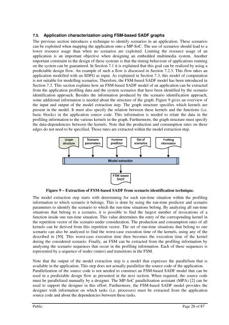
some additional information is needed about the structure of the graph. Figure 9 gives an overview of<br />
the input and output of the model extraction step. The graph structure specifies which kernels are<br />
present in the model. It must also specify the relation between these kernels and the functions (i.e.<br />
basic blocks) in the application source code. This information is needed to relate the data in the<br />
profiling information to the various kernels in the graph. Furthermore, the graph structure must specify<br />
the data-dependencies between the kernels. Note that the production and consumption rates on these<br />
edges do not need to be specified. Those rates are extracted within the model extraction step.<br />
Figure 9 – Extraction of FSM-based SADF from scenario identification technique.<br />
The model extraction step starts with determining for each run-time situation within the profiling<br />
information to which scenario it belongs. This is done by using the run-time predictor and scenario<br />
parameters to identify the scenario to which the run-time situations belong. By analyzing all run-time<br />
situations that belong to a scenario, it is possible to find the largest number of invocations of a<br />
function inside one run-time situation. This value determines the entry of the corresponding kernel in<br />
the repetition vector of the scenario under consideration. The production and consumption rates of all<br />
kernels can be derived from this repetition vector. The set of run-time situations that belong to one<br />
scenario can also be analyzed to find the worst-case execution time of the kernels, using any of the<br />
described in [50]. This worst-case execution time then becomes the execution time of the kernel<br />
during the considered scenario. Finally, an FSM can be extracted from the profiling information by<br />
analyzing the scenario sequences that occur in the profiling information. Each of these sequences is<br />
represented by a sequence of nodes (states) and transitions in the FSM.<br />
Note that the output of the model extraction step is a model that expresses the parallelism that is<br />
available in the application. This step does not actually parallelize the source code of the application.<br />
Parallelization of the source code is not needed to construct an FSM-based SADF model that can be<br />
used in a predictable design flow as presented in the next section. When required, the source code<br />
must be parallelized manually by a designer. The MP-SoC parallelization assistant (MPA) [2] can be<br />
used to support the designer in this effort. Furthermore, the FSM-based SADF model provides the<br />
designer with information on which tasks (i.e. processes) must be extracted from the application<br />
source code and about the dependencies between these tasks.<br />
Public Page 26 of 87