MNEMEE - Electronic Systems - Technische Universiteit Eindhoven
MNEMEE - Electronic Systems - Technische Universiteit Eindhoven
MNEMEE - Electronic Systems - Technische Universiteit Eindhoven

Create successful ePaper yourself
Turn your PDF publications into a flip-book with our unique Google optimized e-Paper software.
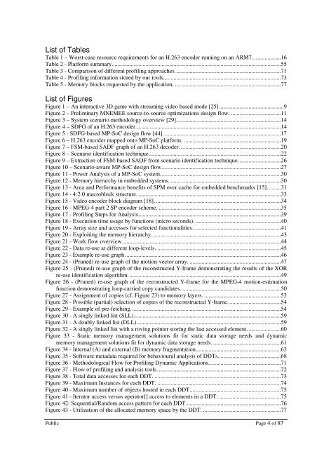
List of Tables<br />
Table 1 – Worst-case resource requirements for an H.263 encoder running on an ARM7. ..................16<br />
Table 2 - Platform summary...................................................................................................................55<br />
Table 3 - Comparison of different profiling approaches. .......................................................................71<br />
Table 4 - Profiling information stored by our tools. ...............................................................................73<br />
Table 5 - Memory blocks requested by the application. ........................................................................77<br />
List of Figures<br />
Figure 1 – An interactive 3D game with streaming video based mode [25]. ...........................................9<br />
Figure 2 – Preliminary <strong>MNEMEE</strong> source-to-source optimizations design flow. ..................................11<br />
Figure 3 – System scenario methodology overview [29]. ......................................................................14<br />
Figure 4 – SDFG of an H.263 encoder. ..................................................................................................14<br />
Figure 5 - SDFG-based MP-SoC design flow [44]. ...............................................................................17<br />
Figure 6 – H.263 encoder mapped onto MP-SoC platform. ..................................................................19<br />
Figure 7 – FSM-based SADF graph of an H.263 decoder. ....................................................................20<br />
Figure 8 – Scenario identification technique. .........................................................................................22<br />
Figure 9 – Extraction of FSM-based SADF from scenario identification technique. ............................26<br />
Figure 10 – Scenario-aware MP-SoC design flow. ................................................................................27<br />
Figure 11 - Power Analysis of a MP-SoC system. .................................................................................30<br />
Figure 12 - Memory hierarchy in embedded systems. ...........................................................................30<br />
Figure 13 - Area and Performance benefits of SPM over cache for embedded benchmarks [15]. ........31<br />
Figure 14 - 4:2:0 macroblock structure. .................................................................................................33<br />
Figure 15 - Video encoder block diagram [18]. .....................................................................................34<br />
Figure 16 - MPEG-4 part 2 SP encoder scheme. ...................................................................................35<br />
Figure 17 - Profiling Steps for Analysis. ................................................................................................39<br />
Figure 18 - Execution time usage by functions (micro seconds). ..........................................................40<br />
Figure 19 - Array size and accesses for selected functionalities. ...........................................................41<br />
Figure 20 - Exploiting the memory hierarchy. .......................................................................................43<br />
Figure 21 - Work flow overview. ...........................................................................................................44<br />
Figure 22 - Data re-use at different loop-levels. ....................................................................................45<br />
Figure 23 - Example re-use graph. .........................................................................................................46<br />
Figure 24 - (Pruned) re-use graph of the motion-vector array. ..............................................................47<br />
Figure 25 - (Pruned) re-use graph of the reconstructed Y-frame demonstrating the results of the XOR<br />
re-use identification algorithm. .......................................................................................................49<br />
Figure 26 - (Pruned) re-use graph of the reconstructed Y-frame for the MPEG-4 motion-estimation<br />
function demonstrating loop-carried copy candidates. ...................................................................50<br />
Figure 27 - Assignment of copies (cf. Figure 23) to memory layers. ....................................................53<br />
Figure 28 - Possible (partial) selection of copies of the reconstructed Y-frame. ...................................54<br />
Figure 29 - Example of pre-fetching. .....................................................................................................54<br />
Figure 30 - A singly linked list (SLL) ....................................................................................................59<br />
Figure 31 - A doubly linked list (DLL) ..................................................................................................59<br />
Figure 32 - A singly linked list with a roving pointer storing the last accessed element. ......................60<br />
Figure 33 - Static memory management solutions fit for static data storage needs and dynamic<br />
memory management solutions fit for dynamic data storage needs. ..............................................61<br />
Figure 34 - Internal (A) and external (B) memory fragmentation..........................................................63<br />
Figure 35 - Software metadata required for behavioural analysis of DDTs. ..........................................68<br />
Figure 36 - Methodological Flow for Profiling Dynamic Applications. ................................................71<br />
Figure 37 - Flow of profiling and analysis tools. ...................................................................................72<br />
Figure 38 - Total data accesses for each DDT. ......................................................................................73<br />
Figure 39 - Maximum Instances for each DDT. ....................................................................................74<br />
Figure 40 - Maximum number of objects hosted in each DDT. .............................................................75<br />
Figure 41 - Iterator access versus operator[] access to elements in a DDT. ..........................................75<br />
Figure 42: Sequential/Random access pattern for each DDT ................................................................76<br />
Figure 43 - Utilization of the allocated memory space by the DDT. .....................................................77<br />
Public Page 4 of 87