Numerical modelin of floating prefabricated vertical drains in layered ...
Numerical modelin of floating prefabricated vertical drains in layered ...
Numerical modelin of floating prefabricated vertical drains in layered ...

You also want an ePaper? Increase the reach of your titles
YUMPU automatically turns print PDFs into web optimized ePapers that Google loves.
II<br />
III<br />
Model<br />
I<br />
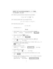
Table 3. Comb<strong>in</strong>ation <strong>of</strong> cases for modell<strong>in</strong>g <strong>float<strong>in</strong>g</strong> PVDs <strong>in</strong> two soil layers for one- and two-way dra<strong>in</strong>age conditions.<br />
E50 ref = Eoed ref<br />
kN/m 2<br />
I. IKHYA & H. F. SCHWEIGER: NUMERICAL MODELING OF FLOATING PREFABRICATED VERTICAL DRAINS IN LAYERED SOIL<br />
Soil Layer I Soil Layer II<br />
Eur ref<br />
kh = kv E50 ref = Eoed ref<br />
kN/m 2 m/s kN/m 2<br />
The excess pore-pressure distributions for homogeneous<br />
and two soil layers are visualized <strong>in</strong> Figure 8.<br />
As expected, excess pore-pressure dissipation <strong>in</strong> the<br />
soil layer that has a high stiffness and permeability is<br />
faster than <strong>in</strong> the soil layer hav<strong>in</strong>g a low stiffness and<br />
permeability. For the <strong>float<strong>in</strong>g</strong> PVD conditions it is clear<br />
that the <strong>vertical</strong> flow is predom<strong>in</strong>ant <strong>in</strong> the unimproved<br />
area under the PVD tip, which has an <strong>in</strong>fluence on the<br />
consolidation time.<br />
The settlement curves from the numerical model for PVD<br />
<strong>in</strong>stallation with vary<strong>in</strong>g the depth <strong>of</strong> penetration are<br />
shown <strong>in</strong> figures 9 and 10. It is clear that for a homogeneous<br />
layer (model 1), the dra<strong>in</strong> length can be reduced by<br />
up to 20% without significantly affect<strong>in</strong>g the consolidation<br />
Eur ref<br />
kh = kv<br />
kN/m 2 m/s<br />
Remarks<br />
1000 3000 1.9x10 -9 1000 3000 1.9x10 -9 Homogeneous soil layer<br />
A 1000 3000 1.9x10 -9 1000 3000 5.0x10 -9 Value <strong>of</strong> soil permeability <strong>in</strong> layer II is higher than layer I<br />
B 1000 3000 1.9x10 -9 3000 9000 1.9x10 -9 Value <strong>of</strong> soil stiffness <strong>in</strong> layer II is higher than layer I<br />
C 1000 3000 1.9x10 -9 3000 9000 5.0x10 -9 Value <strong>of</strong> soil stiffness and permeability <strong>in</strong> layer II are higher than layer I<br />
A 1000 3000 5.0x10 -9 1000 3000 1.9x10 -9 Value <strong>of</strong> soil permeability <strong>in</strong> layer I is higher than layer II<br />
B 3000 9000 1.9x10 -9 1000 3000 1.9x10 -9 Value <strong>of</strong> soil stiffness <strong>in</strong> layer I is higher than layer II<br />
C 3000 9000 5.0x10 -9 1000 3000 1.9x10 -9 Value <strong>of</strong> soil stiffness and permeability <strong>in</strong> layer I are higher than layer II<br />
process (L/H = 0.8). This result corresponds to the report<br />
<strong>of</strong> Indraratna and Rujikiatkamjorn [7]. For the two-soillayer<br />
condition where the second layer is stiffer and more<br />
permeable than the first layer (model 2; IIA, IIB, IIC),<br />
the dra<strong>in</strong> length can be shortened by 30–40% without<br />
affect<strong>in</strong>g the consolidation process (L/H = 0.7 – 0.6)<br />
significantly. In contrast, for the two-soil-layer condition<br />
where the first layer is stiffer and more permeable than the<br />
second layer (model 3; IIIA, IIIB, IIIC), the dra<strong>in</strong> length<br />
can be reduced by only 10–20% without significantly<br />
affect<strong>in</strong>g the consolidation process (L/H = 0.9 – 0.8). It<br />
is <strong>in</strong>terest<strong>in</strong>g to note that the differences <strong>in</strong> stiffness and<br />
permeability <strong>in</strong> the two-soil-layer condition have an <strong>in</strong>fluence<br />
on the optimum penetration depth (L/H), especially<br />
<strong>in</strong> the unimproved area below the PVD tip.<br />
Figure 8. Excess pore-pressure distribution for homogeneous and two soil layers for double dra<strong>in</strong>age conditions.<br />
ACTA GEOTECHNICA SLOVENICA, 2012/2 31.