o - Finite Element Method Magnetics
o - Finite Element Method Magnetics
o - Finite Element Method Magnetics

You also want an ePaper? Increase the reach of your titles
YUMPU automatically turns print PDFs into web optimized ePapers that Google loves.
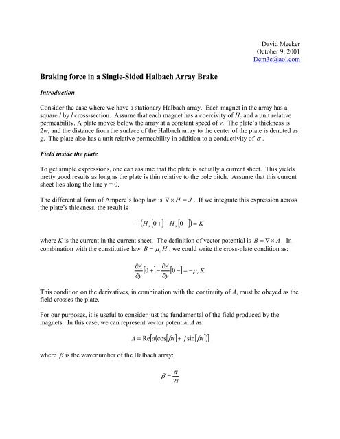
Braking force in a Single-Sided Halbach Array Brake<br />
Introduction<br />
David Meeker<br />
October 9, 2001<br />
Dcm3c@aol.com<br />
Consider the case where we have a stationary Halbach array. Each magnet in the array has a<br />
square l by l cross-section. Assume that each magnet has a coercivity of Hc and a unit relative<br />
permeability. A plate moves below the array at a constant speed of v. The plate’s thickness is<br />
2w, and the distance from the surface of the Halbach array to the center of the plate is denoted as<br />
g. The plate also has a unit relative permeability in addition to a conductivity of σ .<br />
Field inside the plate<br />
To get simple expressions, one can assume that the plate is actually a current sheet. This yields<br />
pretty good results as long as the plate is thin relative to the pole pitch. Assume that this current<br />
sheet lies along the line y = 0.<br />
The differential form of Ampere’s loop law is ∇ × H = J . If we integrate this expression across<br />
the plate’s thickness, the result is<br />
( [ 0 + ] − H [ −]<br />
) = K<br />
− 0<br />
H x<br />
x<br />
where K is the current in the current sheet. The definition of vector potential is B = ∇ × A . In<br />
combination with the constitutive law = µ H , we could write the cross-plate condition as:<br />
∂A<br />
∂y<br />
B o<br />
∂A<br />
∂y<br />
[ 0 + ] − [ 0 −]<br />
= −µ<br />
K<br />
This condition on the derivatives, in combination with the continuity of A, must be obeyed as the<br />
field crosses the plate.<br />
For our purposes, it is useful to consider just the fundamental of the field produced by the<br />
magnets. In this case, we can represent vector potential A as:<br />
[ a(<br />
cos[<br />
βx] j sin[<br />
x]<br />
) ]<br />
A = Re + β<br />
where β is the wavenumber of the Halbach array:<br />
π<br />
β =<br />
2l<br />
o
We could then split the field into two parts:<br />
a = a + a<br />
where as is the field due to the Halbach array in the absence of the plate, and ar is the reaction<br />
field from the currents in the plate.<br />
The current in the plate is due to the motion of the plate in the field of the Halbach array. The<br />
current density is:<br />
s<br />
r<br />
J = σ v × B<br />
If we integrate the current across the plate and re-write in terms of a, we get:<br />
k = − ( 2 j βvσw)(<br />
a + a )<br />
Outside the plate, the equation that the magnetic field must then obey is:<br />
which can be solve by inspection to yield a<br />
a<br />
r<br />
a<br />
r<br />
2<br />
d a 2<br />
− β a = 0<br />
2<br />
dy<br />
o<br />
−β<br />
y<br />
= a e for y > 0<br />
o<br />
β y<br />
= a e for y < 0<br />
The interface condition can then be used to determine the unknown constant, ao:<br />
o<br />
o<br />
s<br />
( 2 jβvσµ<br />
w)<br />
( a [ ] a )<br />
− β a − βa<br />
=<br />
0 +<br />
For ease of notation, we can define the “modified slip” as:<br />
o<br />
= vσµ<br />
w<br />
sm o<br />
and we can also note that the time constant of the plate then must be:<br />
Now, we can solve for ao as a function of as:<br />
σµ ow<br />
τ =<br />
β<br />
o<br />
s<br />
o
and the total a inside the plate as:<br />
a<br />
o<br />
⎛ − js<br />
=<br />
⎜<br />
⎝1<br />
+ js<br />
⎛ 1<br />
a =<br />
⎜<br />
⎝1<br />
+ js<br />
The above represents the field as a simple function of the plate’s velocity and the “source” field<br />
produced by the halbach array magnets.<br />
Forces on the plate<br />
The best way to get force in this case is to integrate the J × B force across the plate to get the<br />
pressure:<br />
The flux passing normal to the plate is:<br />
and the current flowing in the plate is:<br />
b<br />
y<br />
m<br />
m<br />
m<br />
1<br />
Re<br />
2<br />
⎞<br />
⎟<br />
⎟a<br />
⎠<br />
⎞<br />
⎟<br />
⎟a<br />
⎠<br />
s<br />
[] 0<br />
s<br />
[] 0<br />
[ b k ]<br />
P = − y<br />
− jβ<br />
= − jβ<br />
a = a<br />
1+<br />
js<br />
2 jβsma<br />
1 2 jβs<br />
k = − = −<br />
µ µ 1+<br />
js<br />
Using these expressions to evaluate the pressure yields:<br />
o<br />
⎛ s<br />
P = −⎜<br />
⎜<br />
⎝1<br />
+<br />
m<br />
2<br />
sm<br />
o<br />
⎟ ⎞<br />
⎠<br />
m<br />
( βa<br />
)<br />
The total force would then be obtained by multiplying by the surface area of the Halbach array.<br />
Right away, this form give some interesting results. By inspection, one can see that the braking<br />
pressure is optimized at s = 1.<br />
At the peak of the curve, the velocity is<br />
and the peak pressure is:<br />
m<br />
1<br />
v =<br />
wσµ<br />
o<br />
µ<br />
s<br />
o<br />
2<br />
s<br />
m<br />
m<br />
a<br />
s
Field from the Halbach array<br />
P =<br />
2 ( βa<br />
)<br />
The last part that remains to be determined is as, the field component at the plate’s center due to<br />
the Halbach array in free space. If one considers just the fundamental of the array, the array can<br />
be represented as a sinusoidally distributed current density of amplitude Jh sandwiched between<br />
two current sheets of strength Kh on the bottom of the array and –Kh on the top of the array.<br />
Creating Jh and Kh just consists of evaluating Fourier series coefficients to obtain:<br />
One then needs to solve:<br />
d<br />
2<br />
s<br />
2<br />
2<br />
− β as<br />
= −µ<br />
o h δ<br />
dy<br />
a<br />
s<br />
2µ<br />
o<br />
2 2<br />
J h = βH<br />
π<br />
K<br />
h<br />
2 2<br />
=<br />
π<br />
( K ( δ[<br />
y − g]<br />
− [ y − g − l]<br />
) + J ( u[<br />
y − g]<br />
− u[<br />
y − g − l])<br />
)<br />
where u[y] and δ [y]<br />
are the unit step and Dirac delta functions respectively. The implication<br />
here is that the array is located a distance of g above the plate’s center.<br />
Skipping over the solution of this ODE, the field at the center of the plate is:<br />
Example<br />
a<br />
s<br />
⎛<br />
⎜ 4<br />
=<br />
⎜<br />
⎜<br />
⎜<br />
⎝<br />
⎡π<br />
⎤<br />
2 sinh<br />
⎢<br />
⎣<br />
⎥<br />
exp<br />
4 ⎦<br />
βπ<br />
h<br />
H<br />
c<br />
c<br />
[ − ( βg<br />
+ π / 4)<br />
]<br />
µ H<br />
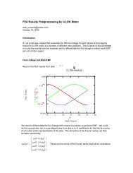
As a giggle test, one can compare to a finite element run. In this case, the magnets have Hc = 10 6<br />
A/m, l = 0.75”, g=0.1875”, w=0.0625”, σ =25 MS/m. The plate is traveling past at 4.572 m/s,<br />
which corresponds to a frequency of 120 Hz and a sm of 0.456. A section 1.5” long in the travel<br />
direction has been modeled.<br />
o<br />
c<br />
⎞<br />
⎟<br />
⎟<br />
⎟<br />
⎟<br />
⎠
The finite element solution yields an average force of 4327 N/m; the “simple” analytical formula<br />
predicts a force of 4191 N/m.<br />
Conclusions<br />
By assuming that the plate can be approximated as current sheet, some fairly simple expressions<br />
for braking pressure versus speed can be derived for a single-sided brake. In these formulas, the<br />
magnet geometry is clearly in evidence, and simple expressions are available for the peak<br />
braking force and the velocity at which it occurs. The answer shows a good agreement to a finite<br />
element analysis for a rather arbitrary test case (~3% difference between analytical solution and<br />
FEA).<br />
This solution does not include skin effects. Plates that are thick compared to the wavelength are<br />
also not addressed. It would be straightforward to extend the solution to encompass these cases<br />
as well, with the expense of some loss of simplicity. A double-sided brake could be<br />
accommodated more easily (just scales force by a factor of 4).<br />
It should also be noted that the above is a purely 2D solution. In the “real world,” the eddy<br />
currents have to “turn around” in at the edges of the plate—this creates some extra resistance and<br />
inductance. Most of the effect can be captured by a relatively simple correction to the plate’s<br />
conductivity that accounts for the increased resistance.