You also want an ePaper? Increase the reach of your titles
YUMPU automatically turns print PDFs into web optimized ePapers that Google loves.
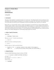
LRK Motor Analysis Worksheet<br />
edie_currants@yahoo.com<br />
October 19, 2004<br />
Introduction<br />
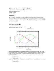
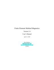
This worksheet considers the analysis of a "LRK" motor. This type of motor is an "inside-out"<br />
machine with a rotor on the outside of the machine. The typical configuration, considered in this<br />
worksheet, has a 12-tooth stator and a 14 pole rotor. Only every other tooth of the stator is<br />
wound, and each winding only encircles a single tooth. Each phase contains a total of 2 coils,<br />
and these coils are wound in series. The topology, and some of the key dimensions, are pictured<br />
below.<br />
The purpose of this worksheet is to predict the circuit parameters of the machine, ultimately<br />
allowing the voltage and current to be estmated for a desired torque and speed. The equations<br />
used in the worksheet are somewhat approximate, but they allow a design to be baselined<br />
before moving on to more elaborate analysis methods like FEA.
Preliminary Definitions:<br />
µ o 4⋅π 10 7 − H<br />
:= ⋅ ⋅<br />
m<br />
Arms :=<br />
Machine Geometry:<br />
See the above figure for each of the dimensions rendered on a drawing of the machine.<br />
rstator := 12.8⋅mm rrotor := 14.14⋅mm tm := 0.9⋅mm wm := 5mm ⋅<br />
n := 15<br />
p := 7<br />
gtot := rrotor − rstator h := 5⋅mm 2⋅A ( )<br />
dslot := 0.77⋅mm wslot := 1.6⋅mm MGOe 10 6 := ⋅gauss⋅oersted Vrms :=<br />
2⋅V Outer radius of the stator<br />
Inner radius of the rotor<br />
Radial thickness of each magnet<br />
Width of each magnet<br />
Number of turns per coil<br />
RPM :=<br />
π⋅rad 30⋅sec Number of pole pairs on the rotor. Although the usual LRK<br />
machine has 7 pole pairs (i.e. 14 magnets on the rotor), the<br />
same stator configuration also supports a 5 pole pair rotor and<br />
generates more or less the same torque per amp*turn as the<br />
p=7 rotor.<br />
Total distance between stator iron and rotor iron<br />
Axial length of the stator stack. It is usually a good idea<br />
to design the magnets so that they are of greater axial<br />
extent than the stator, to accommodate inevitable flux<br />
leakage in the axial direction from the permanent<br />
magnets.<br />
These slot dimensions are used for computing leakage<br />
inductance. In this sort of machine, leakage accounts for a lot<br />
of the machine's inductance and needs to be considered to<br />
get a good estimate of the voltage drop over the internal<br />
impedance in the machine.
Magnet Properties:<br />
BHmax := 40⋅MGOe Energy product of the magnets<br />
Br :=<br />
4 ⋅µ o⋅BHmax<br />
Br = 1.264911 T<br />
Wire Properties:<br />
Torque<br />
Remanence of the permanent magnet, assuming that the<br />
magnet's permeability is the same as free space--an OK<br />
assumption for NdFeB or SmCo magnets.<br />
σ 58 10 6 S<br />
:= ⋅ ⋅<br />
Conductivity of the winding material. 58 MS/m is the<br />
m<br />
conductivity of copper at room temperature.<br />
AWG := 22<br />
Gauge of wire used to wind the stator<br />
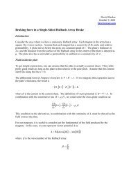
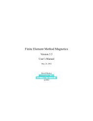
To estimate torque, the easiest approach may be to consider the interaction of one tooth with<br />
the stator magnets when they are positioned above the tooth of interest so as to produce<br />
maximum torque. This configuration is shown in the picture below:
The trick is to remember that permanent magnets can be idealized as sheets of current that<br />
flow around the edges of an equivalent volume filled with air. We can use this idealization to<br />
compute torque on the magnets in a fairly straightforward way. The magnitude of the total<br />
current on each side of each magnet is Hc (the coercivity of the magnet) multiplied by tm, the<br />
thickness of the magnet. The force on a current subjected to a magnetic field (i.e. that produce<br />
by the coils in the stator) is i X B -- this is known as the "Lorentz force." Summing the<br />
contributions from each magnet, the i in the Lorentz force equation is 2*Hc*tm. We can get the<br />
field in the middle of the tooth due to the coil using magnetic circuit theory:<br />
B = µ o<br />
*n*i/( rrotor − rstator )<br />
To get torque, we then need to multiply by a moment arm, which we could say is the center of<br />
the gap in which the magnets are located, ( rrotor + rstator) /2. Multiplying all of this together,<br />
and multiplying bythe axial length of the machine, we get the single-pole result:<br />
τ onepole =<br />
⎛<br />
⎜<br />
⎝<br />
rrotor + rstator rrotor − rstator ⎞<br />
⎠<br />
⋅Br⋅h⋅ tm⋅n⋅ i<br />
To get the torque for the entire machine, we need to recall that there are 2 wound teeth per<br />
phase. Then, if we assume that the machine has a roughly trapezoidal back-EMF, so that we<br />
drive 2 out of the three phases full-on at any time, the total torque is 4X the one pole result.<br />
iphase := 4.0⋅A Design current amplitude<br />
⎛<br />
rrotor + rstator Kp := 2⋅⎜<br />
⋅B rrotor − r<br />
r⋅h⋅tm⋅<br />
n<br />
stator<br />
⎝<br />
Kp 3.433101 10 3 −<br />
= × Wb<br />
τ := 2Kp⋅iphase τ = 0.027465 N⋅m τ =<br />
0.243084 lbf⋅in ⎞<br />
⎠<br />
Where Kp represents the height of the plateau on<br />
a roughly trapezoidal back-EMF waveform for a<br />
phase.<br />
Torque produced by the motor when driven<br />
with 2 phases on and one off with the two "on"<br />
phases carrying currents of amplitude i phase<br />
An OK reference for terminology, etc., is:<br />
http://www.eece.maine.edu/motor/BPMM_Ch8.pdf
Self-Inductance of Each Phase<br />
gap := rrotor − rstator gap<br />
Rgap :=<br />
⎡π⋅(<br />
rrotor + rstator) ⎤<br />
µ o⋅⎢<br />
⎥⋅(<br />
h + 2gap)<br />
12<br />
⎣<br />
wslot Rleak :=<br />
µ o⋅( dslot + 2w ⋅ slot)<br />
⋅ h + 2⋅wslot ⎦<br />
( )<br />
Magnetic reluctance of the air gap<br />
between the rotor and stator. This<br />
uses an old but good kludge of<br />
augmenting the area of the flux path<br />
by the air gap width times the<br />
perimeter of the gap.<br />
2n<br />
Lgap 2<br />
⋅<br />
:= Inductance due to flux that crosses from<br />
Rgap the stator to the rotor and back<br />
Lgap = 0.022858 mH<br />
4n<br />
Lleak 2<br />
⋅<br />
:= Leakage inductance from flux that crosses over to<br />
Rleak the neighboring unwound poles<br />
Lleak =<br />
0.023011 mH
Lphase :=<br />
Lleak + Lgap Lphase 4.586942 10 5 −<br />
= × H<br />
Resistance of Each Phase<br />
( 2⋅π⋅ rstator) dturn :=<br />
12<br />
lwire := 2n ⋅ ⋅ π⋅dturn + 2h ⋅<br />
dwire( awg)<br />
( 0.325105⋅in) e 0.115958 − awg ⋅<br />
:=<br />
⋅<br />
awire :=<br />
π dwire( AWG)<br />
2<br />
4<br />
lwire Rphase :=<br />
σ⋅awire ( )<br />
Rphase = 0.049301 Ω<br />
Equivalent Circuit, Operating Point<br />
Inductance of each phase<br />
End turn diameter. We will guesstimate that this is the<br />
same as the stator tooth pitch at the surface of the stator<br />
Total length of wire in one phase, guesstimated to the<br />
circumference of a circle with the "end turn diameter"<br />
computed above, plus the length of wire required to run<br />
down one side of the slot and back the other. The leading<br />
2 is because there are two n-turn coils per phase.<br />
A convenient formula for wire diameter as<br />
a function of AWG wire gauge, regressed<br />
from a published table of wire sizes<br />
This is a per-phase steady-state circuit model of<br />
the motor. It's useful for predicting voltage and<br />
power.<br />
We could pretend that this is like a typical three-phase machine by computing the amplitude<br />
of the fundamentals of back-EMF and current, then plugging these in to get voltage, efficiency,<br />
etc.
φ :=<br />
Vphase := ( j⋅ω Lphase + Rphase) ⋅ifund + ω⋅φ Vphase = 2.199552 + 0.741516i V<br />
V phase<br />
V∆ :=<br />
⎛<br />
⎜<br />
⎝<br />
ifund :=<br />
2⋅3 π<br />
⎛<br />
⎜<br />
⎝<br />
We can then plug values into the circuit equation to get information about voltage,<br />
power, efficiency, etc.<br />
V∆ = 4.020401 V<br />
3<br />
Preal 2 Re Vphase i ⎯<br />
:= ⋅ ⋅ fund<br />
Preal = 14.552117 W<br />
3<br />
Papparent 2 V := ⋅ phase ⋅ ifund Papparent = 15.3568 V⋅A 3<br />
τfund 2 p ⋅ φ ⋅ i := ⋅ fund<br />
Pmech := τfund⋅ωmech Pmech = 13.113479 W<br />
Pmech η :=<br />
Preal ⎞<br />
⎠<br />
ω := p⋅ω mech<br />
Kp ⋅<br />
p<br />
ωmech := 5000⋅RPM 2⋅3 π<br />
= 2.321179 V<br />
3⋅Vphase ⎞<br />
⎠ i ⋅ phase<br />
( )<br />
Amplitude of the fundamental of the back-EMF of a trapezoidal<br />
waveform for one phase<br />
Mechanical speed at which the shaft is spinning<br />
Corresponding electrical frequency<br />
Fundamental of the phase current waveform<br />
Phase Voltage Amplitude needed for the required torque<br />
Line-to-line voltage if the machine is Wye-configured.<br />
We could probably interpret this as the DC bus voltage<br />
for the two-phase-on system.<br />
Real power = mechanical power + losses<br />
Apparent power = volt*amp product that must<br />
actually be accommodated by the drive electronics<br />
Mechanical output power<br />
η = 0.901139
Suggested Iron Cross-Section Sizing<br />
Bgap := Br⋅ Bgap wleg := wm⋅ Bmax wleg = 2.359909 mm<br />
wleg wbackiron :=<br />
2<br />
wbackiron = 1.179954 mm<br />
Wire Sizing<br />
irms :=<br />
⎛<br />
⎜<br />
⎝<br />
Bmax := 1.8⋅T 2<br />
3 i ⋅ phase<br />
tm rrotor − rstator irms 10.024119<br />
awire A<br />
mm 2<br />
=<br />
na ⋅ wire 4.887192 mm 2<br />
=<br />
⎞<br />
⎠<br />
Air gap flux density<br />
Minimum "Leg" region iron thickness required to carry<br />
the flux from the permanent magnet.<br />
The back iron and rotor iron need about half the<br />
cross-section as the leg section to carry the flux from<br />
the magnets--in the case where all the flux goes<br />
down the "leg", half of the flux goes to the left, and<br />
half of the flux goes to the right....<br />
Relation of RMS to peak current density for the two-phases-on<br />
strategy<br />
Current density in the wire. As a rule of thumb, it's<br />
good to stay below 10 A/mm^2. However, the<br />
maximum current density is really determined by how<br />
well the design can get the heat produced via<br />
resistive losses out.<br />
Cross-section area of copper in each slot. As another rule<br />
of thumb, it's good to make sure that the copper area is<br />
less than half of the total slot area so that the winding<br />
can actually be constructed.
Conclusions<br />
The above represents a somewhat rough crack at analyzing an LRK motor designed to have a<br />
trapezoidal back-EMF and driven by a two-phase-on drive.<br />
Several potentially important effects have been neglected. Efficiency should be expected to be<br />
worse than predicted by the worksheet, since core losses have been neglected. Eddy current<br />
losses in the magnets and solid rotor iron will also decrease efficiency to some degree,<br />
although this is probably a second-order effect compared to core losses in the stator iron.<br />
Lastly, what would probably be even more useful is to put the math used in this worksheet<br />
together in a different order, so as to perform a design optimization. Probably the way to do<br />
this would be to prescribe:<br />
•<br />
•<br />
•<br />
•<br />
•<br />
•<br />
•<br />
•<br />
Maximum allowable average current density in the slots;<br />
Magnet grade;<br />
Operating speed;<br />
Torque;<br />
Drive voltage;<br />
Number of magnets (i.e. 10-pole or 14-pole design);<br />
Maximum allowable flux density;<br />
Geometric constraints (e.g. stator ID, axial length, etc.)<br />
The program would then perform a minimization to obtain an optimal design, probably in the<br />
sense of minimizing weight, also selecting a wire gauge and turns count.