

3-Phase BLDC Motor Control with Sensorless Back EMF ... - Freescale
3-Phase BLDC Motor Control with Sensorless Back EMF ... - Freescale
3-Phase BLDC Motor Control with Sensorless Back EMF ... - Freescale

You also want an ePaper? Increase the reach of your titles
YUMPU automatically turns print PDFs into web optimized ePapers that Google loves.
Target <strong>Motor</strong> Theory<br />
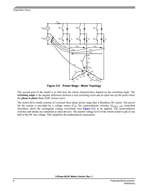
Figure 3-5. Power Stage - <strong>Motor</strong> Topology<br />
The second goal of the model is to find how the motor characteristics depend on the switching angle. The<br />
switching angle is the angular difference between a real switching event and an ideal one (at the point where<br />
the phase to phase <strong>Back</strong>-<strong>EMF</strong> crosses zero).<br />
The motor-drive model consists of a normal three phase power stage plus a Brushless DC motor. The power<br />
for the system is provided by a voltage source (U d). Six semiconductor switches (S A/B/C t/b), controlled<br />
elsewhere, allow the rectangular voltage waveforms (see Figure 3-2) to be applied. The semiconductor<br />
switches and diodes are simulated as ideal devices. The natural voltage level of the whole model is put at one<br />
half of the DC bus voltage. This simplifies the mathematical expressions.<br />
3-<strong>Phase</strong> <strong>BLDC</strong> <strong>Motor</strong> <strong>Control</strong>, Rev. 1<br />
8 <strong>Freescale</strong> Semiconductor<br />
Preliminary


