Masoneilan Products SVI II ESD - GE Energy
Masoneilan Products SVI II ESD - GE Energy
Masoneilan Products SVI II ESD - GE Energy

Create successful ePaper yourself
Turn your PDF publications into a flip-book with our unique Google optimized e-Paper software.
<strong>GE</strong> <strong>Energy</strong><br />
04/10<br />
<strong>Masoneilan</strong> * <strong>Products</strong><br />
<strong>SVI</strong> * <strong>II</strong> <strong>ESD</strong><br />
PST Controller With SIL 3 Emergency Shutdown<br />
Quick Start Guide and<br />
Safety Manual (Rev. D)
Warranty<br />
Items sold by <strong>GE</strong> <strong>Energy</strong> are warranted to be free from defects in materials and workmanship<br />
for a period one (1) year from first use or eighteen (18) months from delivery provided<br />
said items are used according to <strong>GE</strong> recommended usages. <strong>GE</strong> reserves the right to discontinue<br />
manufacture of any product or change product materials, design or specifications<br />
without notice. This instruction manual applies to the following instruments and approved<br />
software: <strong>SVI</strong>* <strong>II</strong> <strong>ESD</strong> and ValVue <strong>ESD</strong>* software.<br />
Software is warranted for ninety (90) days from delivery.<br />
The <strong>SVI</strong> <strong>II</strong> <strong>ESD</strong> series PST controllers are warranted for use only with interface software<br />
approved by <strong>GE</strong>. Consult <strong>GE</strong> factory locations for approved software listing.<br />
About this Guide<br />
This Quick Start Guide applies to the following instruments and approved software:<br />
<strong>SVI</strong> <strong>II</strong> <strong>ESD</strong><br />
with Firmware version 3.1.2<br />
with ValVue <strong>ESD</strong> version 1.0 or greater<br />
with Model HH375 HART Communicator with DD published for <strong>SVI</strong> <strong>II</strong><br />
<strong>ESD</strong><br />
<strong>Masoneilan</strong> Device Type 203 or 0xCB<br />
with PRM PLUG-IN ValVue <strong>ESD</strong> version 1.0 or greater<br />
<br />
The information in this manual is subject to change without prior notice.<br />
The information contained in this manual, in whole or part, shall not be transcribed or copied<br />
without <strong>GE</strong>’s written permission.<br />
In no case does this manual guarantee the merchantability of the PST Controller or the<br />
software or its adaptability to a specific client needs.<br />
Please report any errors or questions about the information in this manual to your local<br />
supplier or visit www.dressermasoneilan.com.<br />
Copyright<br />
All software is the intellectual property of <strong>GE</strong> <strong>Energy</strong>.<br />
The complete design and manufacture is the intellectual property of <strong>GE</strong> <strong>Energy</strong>.<br />
<strong>Masoneilan</strong> * , <strong>SVI</strong> * , and ValVue * are registered trademarks of <strong>GE</strong> <strong>Energy</strong>. All information<br />
contained herein is believed to be accurate at the time of publication and is subject to<br />
change without notice. All other trademarks are the property of their respective corporations,<br />
All information contained herein is believed to be accurate at the time of publication and is<br />
subject to change without notice.<br />
Copyright 2012 by <strong>GE</strong> <strong>Energy</strong>. All rights reserved.<br />
PN 055201359-999-0000 Rev. D
<strong>SVI</strong> <strong>II</strong> <strong>ESD</strong> Quick Start Guide<br />
Document Changes<br />
Version/Date Writer Changes<br />
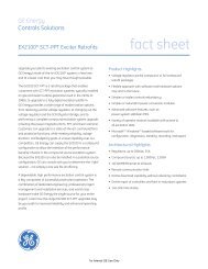
D/5-2012 Don Grefe’ ES-727 updated.
Contents<br />
Introduction . . . . . . . . . . . . . . . . . . . . . . . . . . . . . . . . . . . . . . . . . . . . . . 1<br />
Terms and Abbreviations . . . . . . . . . . . . . . . . . . . . . . . . . . . . . . . . . . . . 1<br />
Section 1 Safety Information . . . . . . . . . . . . . . . . . . . . . . . . . . . 1<br />
Acronyms . . . . . . . . . . . . . . . . . . . . . . . . . . . . . . . . . . . . . . . . . . . . . . . . 2<br />
Documentation Symbols . . . . . . . . . . . . . . . . . . . . . . . . . . . . . . . . . . . 3<br />
Product Safety . . . . . . . . . . . . . . . . . . . . . . . . . . . . . . . . . . . . . . . . . . . . 4<br />
Product Support . . . . . . . . . . . . . . . . . . . . . . . . . . . . . . . . . . . . . . . . . . . 5<br />
Related Literature . . . . . . . . . . . . . . . . . . . . . . . . . . . . . . . . . . . . . . . . . 5<br />
Reference Standards . . . . . . . . . . . . . . . . . . . . . . . . . . . . . . . . . . . . . . . 5<br />
<strong>SVI</strong> <strong>II</strong> <strong>ESD</strong> Device Description . . . . . . . . . . . . . . . . . . . . . . . . . . . . . . . 6<br />
Designing an SIF Using an <strong>SVI</strong> <strong>II</strong> <strong>ESD</strong>. . . . . . . . . . . . . . . . . . . . . . . . . 6<br />
Safety Function . . . . . . . . . . . . . . . . . . . . . . . . . . . . . . . . . . . . . . . . . . . 7<br />
Environmental Limits . . . . . . . . . . . . . . . . . . . . . . . . . . . . . . . . . . . . . . . 7<br />
Design Verification . . . . . . . . . . . . . . . . . . . . . . . . . . . . . . . . . . . . . . . . . 7<br />
SIL Capability . . . . . . . . . . . . . . . . . . . . . . . . . . . . . . . . . . . . . . . . . . . . 8<br />
Connecting the <strong>SVI</strong> <strong>II</strong> <strong>ESD</strong> to the SIS Logic Solver . . . . . . . . . . . . . . . . 9<br />
General Requirements . . . . . . . . . . . . . . . . . . . . . . . . . . . . . . . . . . . . . 9<br />
Installation . . . . . . . . . . . . . . . . . . . . . . . . . . . . . . . . . . . . . . . . . . . . . . 10<br />
<strong>SVI</strong> <strong>II</strong> <strong>ESD</strong> Installation Configurations . . . . . . . . . . . . . . . . . . . . . . . . . 10<br />
Physical Location and Placement Guidelines . . . . . . . . . . . . . . . . . . . 10<br />
Pneumatic Connections . . . . . . . . . . . . . . . . . . . . . . . . . . . . . . . . . . . . 10<br />
Electrical Connections . . . . . . . . . . . . . . . . . . . . . . . . . . . . . . . . . . . . . 10<br />
iii
Operation, Setup, Commissioning. . . . . . . . . . . . . . . . . . . . . . . . . . . 10<br />
Maintenance. . . . . . . . . . . . . . . . . . . . . . . . . . . . . . . . . . . . . . . . . . . . . 10<br />
Diagnostics . . . . . . . . . . . . . . . . . . . . . . . . . . . . . . . . . . . . . . . . . . . . . 10<br />
PST . . . . . . . . . . . . . . . . . . . . . . . . . . . . . . . . . . . . . . . . . . . . . . . . . . . 10<br />
Introduction . . . . . . . . . . . . . . . . . . . . . . . . . . . . . . . . . . . . . . . . . . . . . 13<br />
Section 2 Installation and <br />
Maintenance 13<br />
Using the Quick Start Guide . . . . . . . . . . . . . . . . . . . . . . . . . . . . . . . . 14<br />
Installation . . . . . . . . . . . . . . . . . . . . . . . . . . . . . . . . . . . . . . . . . . . . . . 14<br />
Physical Location and Placement Guidelines . . . . . . . . . . . . . . . . . . . 15<br />
<strong>SVI</strong> <strong>II</strong> <strong>ESD</strong> Components . . . . . . . . . . . . . . . . . . . . . . . . . . . . . . . . . . . 16<br />
Mounting the <strong>SVI</strong> <strong>II</strong> <strong>ESD</strong> on Rotary Valves . . . . . . . . . . . . . . . . . . . . . 17<br />
Travel Sensor Alignment . . . . . . . . . . . . . . . . . . . . . . . . . . . . . . . . . . . 19<br />
Mounting the <strong>SVI</strong> <strong>II</strong> <strong>ESD</strong> with NAMUR Kits . . . . . . . . . . . . . . . . . . . . . 20<br />
Mounting the <strong>SVI</strong> <strong>II</strong> <strong>ESD</strong> on Reciprocating Valves . . . . . . . . . . . . . . . 21<br />
Checking the Magnet . . . . . . . . . . . . . . . . . . . . . . . . . . . . . . . . . . . . . . 25<br />
Using ValVue <strong>ESD</strong> to Check Magnet Position . . . . . . . . . . . . . . . . . . . 26<br />
Checking Actuator, Linkages, or Rotary Adapter . . . . . . . . . . . . . . . . . 27<br />
Connecting the Tubing and Air Supply . . . . . . . . . . . . . . . . . . . . . . . . 27<br />
Checking the Air Supply . . . . . . . . . . . . . . . . . . . . . . . . . . . . . . . . . . . 31<br />
Wiring the <strong>SVI</strong> <strong>II</strong> <strong>ESD</strong> . . . . . . . . . . . . . . . . . . . . . . . . . . . . . . . . . . . . . 31<br />
Powering Up the <strong>SVI</strong> <strong>II</strong> <strong>ESD</strong> . . . . . . . . . . . . . . . . . . . . . . . . . . . . . . . . 35<br />
Making Connections to the Terminal Board . . . . . . . . . . . . . . . . . . . . . 40<br />
<strong>SVI</strong> <strong>II</strong> <strong>ESD</strong> Maintenance. . . . . . . . . . . . . . . . . . . . . . . . . . . . . . . . . . . . 41<br />
Repair and Replacement . . . . . . . . . . . . . . . . . . . . . . . . . . . . . . . . . . . 41<br />
Factory Notification . . . . . . . . . . . . . . . . . . . . . . . . . . . . . . . . . . . . . . . 41<br />
Display Cover Removal and Installation . . . . . . . . . . . . . . . . . . . . . . . 42<br />
Overview . . . . . . . . . . . . . . . . . . . . . . . . . . . . . . . . . . . . . . . . . . . . . . . 45<br />
<strong>SVI</strong> <strong>II</strong> <strong>ESD</strong> Setup . . . . . . . . . . . . . . . . . . . . . . . . . . . . . . . . . . . . . . . . . 45<br />
Pushbuttons and Local Display . . . . . . . . . . . . . . . . . . . . . . . . . . . . . . 45<br />
Section 3 Setup, Calibration and PST . . . . . . . . . . . . . . . . . .45<br />
iv
Accessing Pushbuttons . . . . . . . . . . . . . . . . . . . . . . . . . . . . . . . . . . . . 46<br />
Pushbutton Locks and Configuration-Lock Jumper . . . . . . . . . . . . . . . 47<br />
Modes of Operation . . . . . . . . . . . . . . . . . . . . . . . . . . . . . . . . . . . . . . . 49<br />
Configuration . . . . . . . . . . . . . . . . . . . . . . . . . . . . . . . . . . . . . . . . . . . . 51<br />
Calibration . . . . . . . . . . . . . . . . . . . . . . . . . . . . . . . . . . . . . . . . . . . . . . 54<br />
Check-out with a HART Handheld Communicator . . . . . . . . . . . . . . . 55<br />
Diagnostics . . . . . . . . . . . . . . . . . . . . . . . . . . . . . . . . . . . . . . . . . . . . . 56<br />
Partial Stroke Test Diagnostics . . . . . . . . . . . . . . . . . . . . . . . . . . . . . . 56<br />
Partial Stroke Testing . . . . . . . . . . . . . . . . . . . . . . . . . . . . . . . . . . . . . 57<br />
PST Configuration . . . . . . . . . . . . . . . . . . . . . . . . . . . . . . . . . . . . . . . . 57<br />
Starting PST . . . . . . . . . . . . . . . . . . . . . . . . . . . . . . . . . . . . . . . . . . . . 58<br />
Physical and Operational Specifications . . . . . . . . . . . . . . . . . . . . . 59<br />
Section 4 Specifications and References . . . . . . . . . . . . . . . .59<br />
Hazardous Location Installation . . . . . . . . . . . . . . . . . . . . . . . . . . . . 65<br />
v
<strong>GE</strong> <strong>Energy</strong><br />
<strong>SVI</strong> <strong>II</strong> <strong>ESD</strong> Quick Start Guide<br />
This page intentionally left blank.<br />
vi
Safety Information<br />
1<br />
Introduction<br />
This section provides information necessary to design, install, verify and maintain<br />
a Safety Instrumented Function (SIF) utilizing a <strong>Masoneilan</strong> Smart Valve<br />
Interface, <strong>SVI</strong> <strong>II</strong> <strong>ESD</strong>. This manual provides necessary requirements for meeting<br />
the IEC 61508 or IEC 61511 functional safety standards.<br />
Terms and Abbreviations<br />
The following terms and abbreviations are related to safety functions of the <strong>SVI</strong> <strong>II</strong><br />
<strong>ESD</strong> and are used throughout this document.<br />
Safety<br />
Functional<br />
Safety<br />
Basic<br />
Safety<br />
Safety<br />
Assessment<br />
Fail-<br />
Safe<br />
State<br />
Fail Safe<br />
Fail<br />
Dangerous<br />
Freedom from unacceptable risk of harm.<br />
The ability of a system to carry out the actions necessary to achieve or<br />
to maintain a defined safe state for the equipment / machinery / plant /<br />
apparatus under control of the system.<br />
The equipment must be designed and manufactured such that it protects<br />
against risk of damage to persons by electrical shock and other<br />
hazards and against resulting fire and explosion. The protection must<br />
be effective under all conditions of the nominal operation and under<br />
single fault condition.<br />
The investigation to arrive at a judgment - based on evidence - of the<br />
safety achieved by safety-related systems.<br />
State where the <strong>SVI</strong> <strong>II</strong> <strong>ESD</strong> is de-energized and has exhausted Actuator<br />
1 in a single acting configuration or has caused Actuator 1 to be at<br />
an equal or lower pressure than Actuator 2 in a dual acting configuration.<br />
Failure that causes the valve to go to the defined fail-safe state without<br />
a demand from the process.<br />
Failure that does not respond to a demand from the process (i.e. being<br />
unable to go to the defined fail-safe state).<br />
1
<strong>GE</strong> <strong>Energy</strong><br />
<strong>SVI</strong> <strong>II</strong> <strong>ESD</strong> Quick Start<br />
Acronyms<br />
Fail <br />
Dangerous <br />
Undetected<br />
Fail <br />
Dangerous<br />
Detected<br />
Failure that is dangerous and that is not being diagnosed by automatic<br />
stroke testing.<br />
Failure that is dangerous but is detected by automatic stroke <br />
testing.<br />
Fail Failure that does not cause a false trip or prevent the safety function<br />
but does cause loss of an automatic diagnostic and is not<br />
Annunciation <br />
Undetected detected by another diagnostic.<br />
Fail <br />
Annunciation<br />
Detected<br />
Fail No Effect<br />
Low Demand<br />
Mode<br />
Failure that does not cause a false trip or prevent the safety function<br />
but does cause loss of an automatic diagnostic or false diagnostic<br />
indication.<br />
Failure of a component that is part of the safety function but that<br />
has no effect on the safety function.<br />
Mode where the frequency of demands for operation made on a<br />
safety-related system is no greater than twice the proof test <br />
frequency.<br />
The following acronyms are related to safety functions of the <strong>SVI</strong> <strong>II</strong> <strong>ESD</strong> and are<br />
used throughout this document.<br />
FMEDA<br />
HFT<br />
MOC<br />
PFDavg<br />
PST<br />
SFF<br />
SIF<br />
SIL<br />
SIS<br />
Failure Modes, Effects and Diagnostic Analysis<br />
Hardware Fault Tolerance<br />
Management of Change. These are specific procedures often<br />
done when performing any work activities in compliance with government<br />
regulatory authorities.<br />
Average Probability of Failure on Demand<br />
Partial Stroke Test, a test used to detect failure modes in the PST<br />
Controller, actuator, and valve assembly.<br />
Safe Failure Fraction, the fraction of the overall failure rate of a<br />
device that results in either a safe fault or a diagnosed unsafe<br />
fault.<br />
Safety Instrumented Function, a set of equipment intended to<br />
reduce the risk due to a specific hazard (a safety loop).<br />
Safety Integrity Level, discrete level (one out of a possible four)<br />
for specifying the safety integrity requirements of the safety functions<br />
to be allocated to the E/E/PE safety-related systems where<br />
Safety Integrity Level 4 has the highest level of safety integrity<br />
and Safety Integrity Level 1 has the lowest.<br />
Safety Instrumented System – Implementation of one or more<br />
Safety Instrumented Functions. A SIS is composed of any combination<br />
of sensor (s), logic solver (s), and final element (s).<br />
2
Safety Information<br />
Documentation Symbols<br />
Documentation Symbols<br />
Conventions used in this manual are as follows:<br />
Italicized letters are used when referencing a term used in the program<br />
display window.<br />
Italics is used for emphasis on important items.<br />
Fields where data is entered or user-entered data is italicized.<br />
Actions performed on buttons, checkboxes, etc. appear bolded. For<br />
example: Click Done.<br />
<strong>SVI</strong> <strong>II</strong> <strong>ESD</strong> instructions contain WARNINGS, CAUTIONS labels and Notes,<br />
where necessary, to alert you to safety related or other important information.<br />
Read the instructions carefully before installing and maintaining your instrument.<br />
Total compliance with all WARNING, and CAUTION notices is required for safe<br />
operation.<br />
WARNING<br />
Indicates a potentially hazardous situation,<br />
which if not avoided could result in serious injury<br />
or death.<br />
CAUTION<br />
Indicates a potentially hazardous situation,<br />
which if not avoided could result in instrument or<br />
property damage, or data loss.<br />
NOTE<br />
Indicates important facts and conditions.<br />
3
<strong>GE</strong> <strong>Energy</strong><br />
Product Safety<br />
<strong>SVI</strong> <strong>II</strong> <strong>ESD</strong> Quick Start<br />
For <strong>SVI</strong> <strong>II</strong> <strong>ESD</strong> positioners intended for use with industrial compressed air:<br />
Ensure that an adequate pressure relief provision is installed when the application<br />
of system supply pressure could cause peripheral equipment to malfunction.<br />
Installation must be in accordance with local and national compressed air and<br />
instrumentation codes.<br />
General installation, maintenance or replacement<br />
<strong>Products</strong> must be installed in compliance with all local and national<br />
codes and standards by qualified personnel using safe site work<br />
practices. Personal Protective Equipment (PPE) must be used per safe<br />
site work practices.<br />
Ensure proper use of fall protection when working at heights, per safe<br />
site work practices. Use appropriate safety equipment and practices to<br />
prevent the dropping of tools or equipment during installation.<br />
Under normal operation, compressed supply gas is vented from the <strong>SVI</strong><br />
<strong>II</strong> <strong>ESD</strong> to the surrounding area, and may require additional precautions<br />
or specialized installations.<br />
Intrinsically Safe Installation<br />
<strong>Products</strong> certified for use in intrinsically safe installations MUST BE:<br />
Installed, put into service, used and maintained in compliance with<br />
national and local regulations and in accordance with the<br />
recommendations contained in the relevant standards concerning those<br />
environments.<br />
Used only in situations that comply with the certification conditions<br />
shown in this document and after verification of their compatibility with<br />
the zone of intended use and the permitted maximum ambient<br />
temperature.<br />
Installed, put into service and maintained by qualified and competent<br />
professionals who have undergone suitable training for instrumentation<br />
used in such areas.<br />
WARNING<br />
Before using these products with fluids/compressed gases<br />
other than air or for non-industrial applications, consult the<br />
factory. This product is not intended for use in life support<br />
systems.<br />
WARNING<br />
Do not use damaged instruments.<br />
4
Safety Information<br />
WARNING<br />
Product Support<br />
Installation in poorly ventilated confined areas, with any<br />
potential of gases other than oxygen being present, can lead<br />
to a risk of personnel asphyxiation.<br />
Use only genuine replacement parts which are provided by the manufacturer, to<br />
guarantee that the products comply with the essential safety requirements of the<br />
European Directives.<br />
Changes to specifications, structure, and components used may not lead to the<br />
revision of this manual unless such changes affect the function and performance<br />
of the product.<br />
Product Support<br />
For detailed product instructions and technical support refer to the <strong>SVI</strong> <strong>II</strong> <strong>ESD</strong><br />
SIL3 Instruction Manual <strong>GE</strong>A18946.<br />
Related Literature<br />
Documents related to the <strong>SVI</strong> <strong>II</strong> <strong>ESD</strong> include:<br />
Reference Standards<br />
TUV Certificate No. SAS0016/07, Vers. 1.0<br />
Guidelines/References:Safety Integrity Level Selection – Systematic<br />
Methods Including Layer of Protection Analysis, <br />
ISBN 1-55617-777-1, ISA<br />
Control System Safety Evaluation and Reliability, 2nd Edition, <br />
ISBN 1-55617-638-8, ISA<br />
Safety Instrumented Systems Verification, Practical Probabilistic<br />
Calculations, ISBN 1-55617-909-9, ISA<br />
Functional Safety reference standards related to the <strong>SVI</strong> <strong>II</strong> <strong>ESD</strong> include:<br />
IEC 61508: 2000 – Functional safety of electrical/electronic/<br />
programmable electronic safety-related systems<br />
ANSI/ISA 84.00.01-2004 (IEC 61511 Mod.) Functional Safety – Safety<br />
Instrumented Systems for the Process Industry Sector<br />
5
<strong>GE</strong> <strong>Energy</strong><br />
<strong>SVI</strong> <strong>II</strong> <strong>ESD</strong> Device Description<br />
<strong>SVI</strong> <strong>II</strong> <strong>ESD</strong> Quick Start<br />
An <strong>ESD</strong> valve is a valve that is operated to ensure that the process is brought to<br />
its safe state. During normal operation, these <strong>ESD</strong> valves are typically energized<br />
to stay open. In case of an unsafe situation, the <strong>ESD</strong> valve is de-energized by the<br />
Safety System. The <strong>SVI</strong> <strong>II</strong> <strong>ESD</strong> device performs this shutdown function for Safety<br />
Instrumented Functions (SIF) that require field devices to be certified for safety<br />
related applications according to IEC61508 and is certified by TUV for use up to<br />
SIL3 with a HFT of 0 in low demand applications. It is important to note that the<br />
built-in microprocessor is used for valve diagnostics only. The microprocessor has<br />
no direct role in performing the designated safety function therefore the <strong>SVI</strong> <strong>II</strong><br />
<strong>ESD</strong> is considered a Type A device.<br />
The <strong>SVI</strong> <strong>II</strong> <strong>ESD</strong> is a valve controller that mounts on a pneumatically actuated<br />
valve assembly. Its role is to position an emergency shutdown valve to 0% or<br />
100% with a PFDavg in accordance with IEC61508 for SIL3 application.<br />
Because of its capability of monitoring data from its embedded sensors, the <strong>SVI</strong> <strong>II</strong><br />
<strong>ESD</strong> is capable of validating the health of its integral components. Also, with the<br />
ability of partially stroking the <strong>ESD</strong> valve while in normal operations (energized to<br />
stay open); it becomes possible to validate the health of the valve and actuator<br />
assembly. Periodic testing of the <strong>ESD</strong> valve reduces the PFDavg by detecting<br />
dangerous failures.<br />
Designing an SIF Using an <strong>SVI</strong> <strong>II</strong> <strong>ESD</strong><br />
The following must be taken into consideration when designing a SIF (Safety<br />
Instrumented Function) using the <strong>SVI</strong> <strong>II</strong> <strong>ESD</strong>:<br />
“Safety Function” on page 7<br />
“Environmental Limits” on page 7<br />
“Design Verification” on page 7<br />
“SIL Capability” on page 8<br />
“Connecting the <strong>SVI</strong> <strong>II</strong> <strong>ESD</strong> to the SIS Logic Solver” on page 9<br />
“General Requirements” on page 9<br />
6
Safety Information<br />
Safety Function<br />
Safety Function<br />
When de-energized, the <strong>SVI</strong> <strong>II</strong> <strong>ESD</strong> moves to its fail-safe position. For a<br />
single-acting PST controller the safe state is when the port Actuator 1 is<br />
exhausted to a pressure that is less than 1 PSIG (0.069 bar, 6.9 kPa). For a<br />
double-acting PST controller the safe state is when Actuator 1 pressure is equal<br />
or below the Actuator 2 pressure. The valve actuation means must be of a type<br />
that automatically moves the valve to the safe state when the digital valve<br />
controller is in its safe state.<br />
The <strong>SVI</strong> <strong>II</strong> <strong>ESD</strong> is intended to be part of final element subsystem as defined per<br />
IEC 61508 and the achieved SIL level of the designed function must be verified by<br />
the designer.<br />
Environmental Limits<br />
The designer of a SIF must check that the product is rated for use within the<br />
expected environmental limits as stated in Table 10 on page 59.<br />
Application limits<br />
Application limits for the <strong>SVI</strong> <strong>II</strong> <strong>ESD</strong> installed in a SIF include:<br />
Design Verification<br />
The application of the <strong>SVI</strong> <strong>II</strong> <strong>ESD</strong> is limited for SIF where the safe state is<br />
the de-energized state (shutdown) of the valve. The PST Controller may<br />
be operated with either one of two control signals: 4 - 20 mA or <br />
0 - 24 VDC.<br />
With a 4 - 20 mA control signal, normal operation is with a 20 mA current<br />
loop signal to the PST controller. A shutdown command is issued by<br />
taking the current to 5.6 mA or lower.<br />
With a 0 - 24 VDC control signal, normal operation is with a 24 VDC<br />
signal applied to the PST controller. A shutdown command is issued by<br />
interrupting the loop or taking the voltage signal to 3 VDC or lower.<br />
The design verification criteria for the SIF and the <strong>SVI</strong> <strong>II</strong> <strong>ESD</strong> include:<br />
A detailed Failure Mode, Effects, and Diagnostics Analysis (FMEDA)<br />
report is available from the factory. This report details all failure rates and<br />
failure modes as well as the expected lifetime.<br />
The achieved Safety Integrity Level (SIL) of an entire Safety<br />
Instrumented Function (SIF) design must be verified by the designer via<br />
a calculation of PFDavg considering redundant architectures, proof test<br />
interval, proof test effectiveness, any automatic diagnostics, average<br />
repair time and the specific failure rates of all products included in the<br />
SIF. Each subsystem must be checked to assure compliance with<br />
minimum hardware fault tolerance (HFT) requirements. The exida<br />
7
<strong>GE</strong> <strong>Energy</strong><br />
<strong>SVI</strong> <strong>II</strong> <strong>ESD</strong> Quick Start<br />
SIL Capability<br />
exSILentia * tool is recommended for this purpose as it contains accurate<br />
models for the <strong>SVI</strong> <strong>II</strong> <strong>ESD</strong> and its failure rates.<br />
When using an <strong>SVI</strong> <strong>II</strong> <strong>ESD</strong> in a redundant configuration, include a<br />
common cause factor of 5% in safety integrity calculations.<br />
The failure rate data listed in the FMEDA report is only valid for the<br />
useful life time of an <strong>SVI</strong> <strong>II</strong> <strong>ESD</strong>. The failure rates increase sometime<br />
after this time period. Reliability calculations based on the data listed in<br />
the FMEDA report for mission times beyond the lifetime may yield results<br />
that are too optimistic, i.e. the calculated Safety Integrity Level will not be<br />
achieved.<br />
The <strong>SVI</strong> <strong>II</strong> <strong>ESD</strong> meets SIL 3 requirements as outlined below.<br />
Systematic Integrity<br />
The product has met manufacturer design process requirements of Safety<br />
Integrity Level (SIL) 3. These are intended to achieve sufficient integrity against<br />
systematic errors of design by the manufacturer. A Safety Instrumented Function<br />
(SIF) designed with this product must not be used at a SIL level higher than the<br />
statement without prior use justification by end user or diverse technology<br />
redundancy in the design.<br />
Random Integrity<br />
The <strong>SVI</strong> <strong>II</strong> <strong>ESD</strong>’s safety critical function is maintained by a Type A Device.<br />
Therefore based on the SFF > 90%, when the <strong>SVI</strong> <strong>II</strong> <strong>ESD</strong> is used as the only<br />
component in a final element subassembly, a design can meet SIL 3 @ HFT=0.<br />
When the final element assembly consists of many components (<strong>SVI</strong> <strong>II</strong> <strong>ESD</strong>,<br />
quick exhaust valve, actuator, isolation valve, etc.) the SIL must be verified for the<br />
entire assembly using failure rates from all components. This analysis must<br />
account for any hardware fault tolerance and architecture constraints.<br />
Safety Parameters<br />
For detailed failure rate information refer to the Failure Modes, Effects and<br />
Diagnostic Analysis Report for the <strong>SVI</strong> <strong>II</strong> <strong>ESD</strong> available from the factory.<br />
8
Safety Information<br />
Connecting the <strong>SVI</strong> <strong>II</strong> <strong>ESD</strong> to the SIS Logic Solver<br />
Connecting the <strong>SVI</strong> <strong>II</strong> <strong>ESD</strong> to<br />
When connecting the <strong>SVI</strong> <strong>II</strong> <strong>ESD</strong> to the SIS logic solver follow these guidelines:<br />
General Requirements<br />
The <strong>SVI</strong> <strong>II</strong> <strong>ESD</strong> is connected to the safety rated logic solver which is<br />
actively performing the safety function. Connections must be made per<br />
the instructions supplied by the safety rated logic solver.<br />
The output rating of the I/O module must meet or exceed the electrical<br />
specifications of the <strong>SVI</strong> <strong>II</strong> <strong>ESD</strong> as referenced in ES727 ( “Hazardous<br />
Location Installation” on page 65).<br />
The following general requirements for the <strong>SVI</strong> <strong>II</strong> <strong>ESD</strong> must be adhered to:<br />
The system’s response time must be less than process safety time. The<br />
<strong>SVI</strong> <strong>II</strong> <strong>ESD</strong> switches to its fail safe state in less than 100 ms. Response<br />
time is actuator dependent.<br />
You must add the <strong>SVI</strong> <strong>II</strong> <strong>ESD</strong> response time to actuator/valve response<br />
to get overall response time<br />
All SIS components including the <strong>SVI</strong> <strong>II</strong> <strong>ESD</strong> must be operational before<br />
process start-up. The internal diagnostic test that monitors the <strong>SVI</strong> <strong>II</strong><br />
<strong>ESD</strong> for faults has a 1 hour test interval. This test does not partial stroke<br />
the valve.<br />
In order to use the PST as an automatic diagnostic tool the PST must be<br />
scheduled (using ValVue <strong>ESD</strong>) to run at least once per month or ten<br />
times within the expected hazard demand interval whichever comes first.<br />
Detailed failure rate data is specified in the FMEDA report available from<br />
the factory.<br />
You must verify that the <strong>SVI</strong> <strong>II</strong> <strong>ESD</strong> is suitable for use in safety<br />
applications by confirming the <strong>SVI</strong> <strong>II</strong> <strong>ESD</strong>’s nameplate is properly<br />
marked.<br />
Personnel performing maintenance and testing on the <strong>SVI</strong> <strong>II</strong> <strong>ESD</strong> must<br />
be qualified to do so.<br />
Results from the PST and proof tests must be recorded and reviewed<br />
periodically.<br />
The useful life of the <strong>SVI</strong> <strong>II</strong> <strong>ESD</strong> is discussed in the Failure Modes,<br />
Effects and Diagnostic Analysis Report for the <strong>SVI</strong> <strong>II</strong> <strong>ESD</strong>.<br />
9
<strong>GE</strong> <strong>Energy</strong><br />
Installation<br />
<strong>SVI</strong> <strong>II</strong> <strong>ESD</strong> Quick Start<br />
All issues related to installation are outlined below.<br />
<strong>SVI</strong> <strong>II</strong> <strong>ESD</strong> Installation Configurations<br />
Refer to “<strong>SVI</strong> <strong>II</strong> <strong>ESD</strong> Configurations” on page 33.<br />
Physical Location and Placement Guidelines<br />
Refer to “Physical Location and Placement Guidelines” on page 15.<br />
Pneumatic Connections<br />
Refer to “Pneumatic Connections” on page 27.<br />
Electrical Connections<br />
Refer to “Electrical Connection Guidelines” on page 32<br />
Operation, Setup, Commissioning<br />
Refer to “Setup, Calibration and PST” on page 45.<br />
Maintenance<br />
Refer to “<strong>SVI</strong> <strong>II</strong> <strong>ESD</strong> Maintenance” on page 41.<br />
Diagnostics<br />
PST<br />
The <strong>SVI</strong> <strong>II</strong> <strong>ESD</strong> provides several types of diagnostic information:<br />
Continuous device diagnostics<br />
Self diagnostics of the pneumatics and the safety function that run every<br />
hour and require no user configuration<br />
Partial Stroke Testing (PST) diagnostics<br />
You can configure and run PST at runtime. For more information on PST refer to<br />
“Partial Stroke Testing” on page 57.<br />
10
Safety Information<br />
Proof Test<br />
You can also manually run a proof test to detect failures within an <strong>SVI</strong> <strong>II</strong> <strong>ESD</strong> and<br />
<strong>ESD</strong> valve that are not detected by any automatic diagnostics of the system. Of<br />
main concern are undetected failures that prevent the safety instrumented<br />
function from performing its intended function.<br />
The frequency of proof testing, or the proof test interval, is to be determined in<br />
reliability calculations for the safety instrumented functions for which an <strong>SVI</strong> <strong>II</strong><br />
<strong>ESD</strong> is applied. The proof tests must be performed more frequently or as<br />
frequently as specified in the calculation in order to maintain the required safety<br />
integrity of the safety instrumented function.<br />
The following proof test is recommended. Report any failures that are detected<br />
and that compromise functional safety to the factory.<br />
Table 1 Proof Test Steps<br />
PST<br />
Step<br />
Action<br />
1 Read the <strong>SVI</strong> <strong>II</strong> <strong>ESD</strong> data record using a HART handheld device or ValVue<br />
<strong>ESD</strong> software. Resolve any active faults before proceeding.<br />
2 Bypass the valve, or isolate or take other appropriate action to avoid a false<br />
trip, following company Management of Change (MOC) procedures<br />
3 Inspect the <strong>SVI</strong> <strong>II</strong> <strong>ESD</strong> for dirty or clogged ports and other physical damage<br />
4 De-energize the <strong>SVI</strong> <strong>II</strong> <strong>ESD</strong> and observe that the actuator and valve move.<br />
Energize the <strong>SVI</strong> <strong>II</strong> <strong>ESD</strong> after the valve has moved its full stroke length.<br />
5 Inspect the <strong>SVI</strong> <strong>II</strong> <strong>ESD</strong> for dirt, corrosion or excessive moisture. Clean if<br />
necessary and take corrective action to properly clean the air supply. This is<br />
done to avoid incipient failures due to dirty air.<br />
6 Record any failures in your company’s SIF inspection database. Restore the<br />
loop to full operation.<br />
7 Remove the bypass or otherwise restore normal operation<br />
This test detects approximately 99% of possible DU failures in the <strong>SVI</strong> <strong>II</strong> <strong>ESD</strong><br />
(Proof Test Coverage).<br />
The person (s) performing the proof test of an <strong>SVI</strong> <strong>II</strong> <strong>ESD</strong> must be trained in SIS<br />
operations, including bypass procedures, maintenance and company<br />
Management of Change procedures. No special tools are required.<br />
11
<strong>GE</strong> <strong>Energy</strong><br />
<strong>SVI</strong> <strong>II</strong> <strong>ESD</strong> Quick Start Guide<br />
This page intentionally left blank.<br />
12
Installation and <br />
Maintenance<br />
2<br />
Introduction<br />
The <strong>SVI</strong> <strong>II</strong> <strong>ESD</strong> (Emergency Shutdown Device) is our solution to improve process<br />
integrity in a processing plant; designed to prevent and mitigate possibly<br />
uncontrollable situations.<br />
The <strong>SVI</strong> <strong>II</strong> <strong>ESD</strong> is a PST controller that mounts on a pneumatically actuated valve<br />
assembly. Its role is to position an emergency shutdown valve to 0% or 100% with<br />
a probability of failure on demand (PFD) in accordance with IEC61508 for SIL3<br />
application (SIL = Safety Integrity Level). It replaces the solenoid that is typically<br />
utilized to actuate a spring-return or double-acting actuator, while providing<br />
extensive online valve diagnostics.<br />
Figure 1 <strong>SVI</strong> <strong>II</strong> <strong>ESD</strong><br />
13
<strong>GE</strong> <strong>Energy</strong><br />
Using the Quick Start Guide<br />
<strong>SVI</strong> <strong>II</strong> <strong>ESD</strong> Quick Start<br />
The <strong>SVI</strong> <strong>II</strong> <strong>ESD</strong> Quick Start Guide is intended to help an experienced Field<br />
Engineer install, setup, and calibrate an <strong>SVI</strong> <strong>II</strong> <strong>ESD</strong> in the most efficient manner<br />
possible. This document provides basic installation and setup instructions and is<br />
not intended to replace the in-depth information contained in the <strong>SVI</strong> <strong>II</strong> <strong>ESD</strong><br />
Instruction Manual <strong>GE</strong>A18946. If you experience problems that are not<br />
documented in this guide refer to the <strong>Masoneilan</strong> <strong>SVI</strong> <strong>II</strong> <strong>ESD</strong> Instruction Manual<br />
SIL3, <strong>GE</strong>A18946, call your local representative, or go to<br />
www.dressermasoneilan.com. Sales offices are listed on the last page of this<br />
document<br />
Installation<br />
The steps necessary to complete the <strong>SVI</strong> <strong>II</strong> <strong>ESD</strong> installation and software setup<br />
are outlined in Table 1.<br />
Table 1 <strong>SVI</strong> <strong>II</strong> <strong>ESD</strong> Installation Steps<br />
Step No. Procedure Reference<br />
1<br />
2<br />
3<br />
4<br />
5<br />
Attach mounting bracket to the<br />
actuator.<br />
Install the <strong>SVI</strong> <strong>II</strong> <strong>ESD</strong> magnetic<br />
assembly (rotary valves only).<br />
Assemble the <strong>SVI</strong> <strong>II</strong> <strong>ESD</strong> on the<br />
bracket that is mounted to the valve<br />
actuator.<br />
Connect the pneumatic tubing to the<br />
<strong>SVI</strong> <strong>II</strong> <strong>ESD</strong>.<br />
Connect the air supply to the <strong>SVI</strong> <strong>II</strong><br />
<strong>ESD</strong>.<br />
See page page 17 for rotary<br />
valve and page 21 for<br />
reciprocating valve instructions.<br />
See page 17 for instructions.<br />
See page 17 for rotary valve and<br />
page 21 for reciprocating valve<br />
instructions.<br />
See page 27 for instructions.<br />
See page 31 for instructions.<br />
6 Install the wiring for the <strong>SVI</strong> <strong>II</strong> <strong>ESD</strong>. See page 31 for instructions.<br />
7<br />
Connect the PST controller to the<br />
HART Control Loop segment by<br />
installing the <strong>SVI</strong> <strong>II</strong> <strong>ESD</strong> wiring.<br />
See page 34 for instructions.<br />
8 Power up the <strong>SVI</strong> <strong>II</strong> <strong>ESD</strong>. See page 35 for instructions.<br />
14
Installation and<br />
Physical Location and<br />
Table 1 <strong>SVI</strong> <strong>II</strong> <strong>ESD</strong> Installation Steps<br />
Step No. Procedure Reference<br />
9<br />
If appropriate, configure/calibrate<br />
using ValVue <strong>ESD</strong><br />
If appropriate, configure/calibrate<br />
using a HART Hand Held<br />
Communicator<br />
See page 51 and page 54 for<br />
instructions.<br />
See page 55 for instructions.<br />
WARNING<br />
Failure to adhere to the requirements listed in this manual<br />
may cause loss of life and property.<br />
Before installing, using, or carrying out any maintenance<br />
tasks associated with this instrument, READ THE<br />
INSTRUCTIONS CAREFULLY.<br />
Physical Location and Placement Guidelines<br />
When determining the location of the <strong>SVI</strong> <strong>II</strong> <strong>ESD</strong> adhere to the following<br />
guidelines:<br />
The <strong>SVI</strong> <strong>II</strong> <strong>ESD</strong> must be accessible with sufficient room for cabling and<br />
pneumatic connections and must allow manual proof testing.<br />
Pneumatic piping to the actuator must be kept as short and straight as<br />
possible to minimize the airflow restrictions and potential clogging of the<br />
line. Long or kinked pneumatic tubes may also increase the valve<br />
closure time.<br />
The Breather/Vent port must be accessible and must be inspected for<br />
obstruction during manual proof testing.<br />
The <strong>SVI</strong> <strong>II</strong> <strong>ESD</strong> must be mounted in a mild vibration environment (see<br />
specifications at the end of this document). If excessive vibration can be<br />
expected special precautions must be taken to ensure the integrity of<br />
electrical and pneumatic connectors or reduce the vibration using<br />
appropriate damping mounts.<br />
15
<strong>GE</strong> <strong>Energy</strong><br />
<strong>SVI</strong> <strong>II</strong> <strong>ESD</strong> Quick Start<br />
Necessary Precautions<br />
To avoid injury or affecting the process when installing or replacing a PST<br />
controller on a control valve, ensure that:<br />
If the valve is located in a hazardous area make sure the area has been<br />
certified as safe or that all electrical power to the area has been<br />
disconnected before removing any covers or disconnecting any leads.<br />
Shut off air supply to the actuator and to any valve mounted equipment.<br />
Ensure the valve is isolated from the process by either shutting off the<br />
process or using bypass valves for isolation. Tag shutoff or bypass<br />
valves to guard against a turn-on while work is in progress.<br />
Bleed air from actuator and check that valve is in its de-energized<br />
position.<br />
It is now safe to disconnect and remove any valve mounted equipment that is<br />
being replaced.<br />
<strong>SVI</strong> <strong>II</strong> <strong>ESD</strong> Components<br />
Figure 2 provides a drawing of the <strong>SVI</strong> <strong>II</strong> <strong>ESD</strong> components.<br />
<strong>SVI</strong> <strong>II</strong> <strong>ESD</strong> Cover<br />
<strong>SVI</strong> <strong>II</strong> <strong>ESD</strong> Assembled<br />
Pneumatic Train and<br />
Cover (I/P Module, Relay)<br />
I/P<br />
Manifold<br />
Electronics<br />
Module<br />
Pneumatic Relay<br />
Figure 2 <strong>SVI</strong> <strong>II</strong> <strong>ESD</strong> Components<br />
16
Installation and<br />
Mounting the <strong>SVI</strong> <strong>II</strong> <strong>ESD</strong> on Rotary Valves<br />
Mounting the <strong>SVI</strong> <strong>II</strong> <strong>ESD</strong> on<br />
This section describes the procedure for mounting the <strong>SVI</strong> <strong>II</strong> <strong>ESD</strong> on rotary control<br />
valves that have less than 60° rotation, such as a Camflex or a Varimax * . Figure 3<br />
shows a side view of a Camflex actuator and the <strong>SVI</strong> <strong>II</strong> <strong>ESD</strong> actuator mounting<br />
brackets.<br />
Figure 3 Camflex with Mounting Bracket (Side View)<br />
Mounting the <strong>SVI</strong> <strong>II</strong> <strong>ESD</strong> on a Rotary Actuator<br />
Tools required:<br />
3⁄16" Hex Key<br />
5⁄32" Hex Key<br />
3 mm, 4 mm, 5 mm Hex Key<br />
7⁄16" Wrench<br />
To mount the <strong>SVI</strong> <strong>II</strong> <strong>ESD</strong>:<br />
1. Attach the <strong>SVI</strong> <strong>II</strong> <strong>ESD</strong> rotary mounting bracket to the valve actuator using two<br />
(2) 5⁄16 - 18 UNC flat-head cap screws. In the preferred mounting position, the<br />
long end of the mounting bracket is on your left when facing the actuator, for<br />
any position of the valve and actuator.<br />
2. Bolt the extension shaft to the valve position take-off shaft using a 1⁄4 - 28<br />
UNF socket flathead screw. Secure the machine screw holding the extension<br />
shaft with a torque of 144 in-lbs (16.269 N-m).<br />
3. On internal valve pressure the thrust shaft is pushed out to the mechanical<br />
stops, usually a thrust bearing. On valves where the valve position take-off is<br />
mounted directly on the end of the plug shaft, a Camflex for example, the shaft<br />
must be bearing on its stop to properly set up the <strong>SVI</strong> <strong>II</strong> <strong>ESD</strong> PST Controller.<br />
During hydrostatic testing the shaft is thrust to its stop and a normally<br />
tightened packing retains it in that position.<br />
17
<strong>GE</strong> <strong>Energy</strong><br />
<strong>SVI</strong> <strong>II</strong> <strong>ESD</strong> Quick Start<br />
4. On vacuum service, the valve shaft may be drawn into the body by the<br />
vacuum acting on the shaft, but the magnetic coupling must be assembled<br />
flush with the mounting bracket with the shaft pulled fully out to its thrust<br />
bearing. Check that the endplay from the vacuum position to the fully<br />
extended position is less than 0.06 in. (1.524 mm)<br />
5. Slide the magnet holder into the extension shaft. The location of the magnets<br />
is in the ring of the magnet holder. The magnetic axis is the imaginary line<br />
through the center of both magnets.<br />
6. Rotate the magnet holder so that the magnet axis is vertical when the valve is<br />
in the closed position.<br />
7. Align the end of the magnet holder flush with the end of the mounting bracket.<br />
Secure the magnet holder with two M6 set screws.<br />
8. Slide the V-Seal over the magnet holder.<br />
9. Secure the <strong>SVI</strong> <strong>II</strong> <strong>ESD</strong> onto the mounting bracket using four M6 x 20 mm<br />
Socket Head Cap Screws.<br />
10. Ensure no interference exists with the position sensor protrusion.<br />
11. Ensure that the V-Seal makes contact with the skirt around the position sensor<br />
protrusion on <strong>SVI</strong> <strong>II</strong> <strong>ESD</strong> housing.<br />
18
Installation and<br />
Travel Sensor Alignment<br />
Travel Sensor Alignment<br />
Table 2 shows the general guidelines for travel sensor alignment. Review the<br />
table prior to installing the <strong>SVI</strong> <strong>II</strong> <strong>ESD</strong> on a rotary valve actuator for proper<br />
alignment of the magnet.<br />
Table 2 Travel Sensor Alignment<br />
Rotary<br />
Mounting<br />
System<br />
Stroke Direction<br />
Magnet<br />
Orientation<br />
Valve<br />
Position<br />
Sensor<br />
Counts<br />
Rotary<br />
60° Rotation<br />
Clockwise with<br />
increasing setpoint<br />
Full Open<br />
or<br />
Full Closed<br />
-8000 +/- 1500<br />
or<br />
+8000 +/- 1500<br />
(-45°)<br />
>60° Rotation<br />
Counter Clockwise<br />
rotation with increasing<br />
setpoint<br />
Full Open<br />
or<br />
Full Closed<br />
-8000 +/- 1500<br />
or<br />
+8000 +/- 1500<br />
(+45°)<br />
General Rule for<br />
other<br />
configurations<br />
Any amount of rotation<br />
Clockwise or<br />
counterclockwise<br />
50% Travel<br />
(Mid-Stroke)<br />
0 +/- 1000<br />
(0°)<br />
\<br />
19
<strong>GE</strong> <strong>Energy</strong><br />
<strong>SVI</strong> <strong>II</strong> <strong>ESD</strong> Quick Start<br />
Dismantling the <strong>SVI</strong> <strong>II</strong> <strong>ESD</strong> from Rotary Valves<br />
WARNING<br />
Before carrying out any work on the device, power off the<br />
instrument or ensure that the device’s location conditions for<br />
potentially explosive atmosphere permit the safe opening of<br />
the cover.<br />
To remove the <strong>SVI</strong> <strong>II</strong> <strong>ESD</strong> PST Controller from a rotary valve perform Steps 1 - 9<br />
on page 17 in reverse.<br />
Mounting the <strong>SVI</strong> <strong>II</strong> <strong>ESD</strong> with NAMUR Kits<br />
There are two versions of this kit:<br />
20 and 30 mm<br />
50 mm<br />
20 and 30 mm Mounting<br />
Tools required:<br />
3 mm hex key<br />
4 mm hex key<br />
Refer to Figure 4 for this procedure.<br />
To mount using this kit:<br />
1. Attach the mounting bracket to the valve actuator using four (4) M5 x 0.8 x 10<br />
flat-head cap screws.<br />
Quarter Turn<br />
Mounting<br />
Indicator<br />
Figure 4 Namur 20/30 mm Mounting Kit<br />
2. Place the indicator disk with metal insert over the valve actuator shaft and<br />
secure using an M6 x 1.0 x 45 socket-head screw.<br />
20
Installation and<br />
Mounting the <strong>SVI</strong> <strong>II</strong> <strong>ESD</strong> on<br />
3. Place the Quarter Turn Mounting Plate into place sliding it through the<br />
anti-backlash spring into the dowel pin at the end of the plate into the hex head<br />
screw installed in step 2.<br />
4. Secure the plate to the bracket using four (4) flat head cap screws.<br />
50 mm Mounting<br />
Tools required:<br />
3 mm hex key<br />
4 mm hex key<br />
Refer to Figure 5 for this procedure.<br />
To mount using this kit:<br />
1. Attach the mounting bracket to the valve actuator using four (4) M5 x 0.8 x 10<br />
flat-head cap screws.<br />
2. Place the indicator disk with metal insert over the valve actuator shaft.<br />
Quarter Turn<br />
Mounting<br />
Anti-backlash spring<br />
Namur coupling<br />
Indicator<br />
Figure 5 Namur 50 mm Mounting Kit<br />
3. Place the Namur coupling and lever on top of the indicator disc and secure<br />
with an M6 x 1.0 x 25 socket-head screw.<br />
4. Place the Quarter Turn Mounting Plate into place sliding it over the lever and<br />
through the anti-backlash spring.<br />
5. Secure the bracket using four (4) flat head cap screws.<br />
Mounting the <strong>SVI</strong> <strong>II</strong> <strong>ESD</strong> on Reciprocating Valves<br />
The process of mounting the <strong>SVI</strong> <strong>II</strong> <strong>ESD</strong> on a reciprocating valve consists of<br />
mounting the unit on the actuator that is attached to the valve. This section<br />
describes the procedure for mounting the <strong>SVI</strong> <strong>II</strong> <strong>ESD</strong> on Reciprocating Valves<br />
(using <strong>Masoneilan</strong>’s 87⁄88 Multi-Spring actuators as an example).<br />
21
<strong>GE</strong> <strong>Energy</strong><br />
<strong>SVI</strong> <strong>II</strong> <strong>ESD</strong> Quick Start<br />
Mounting the <strong>SVI</strong> <strong>II</strong> <strong>ESD</strong> on a Reciprocating Actuator<br />
Tools required:<br />
7⁄16" Combination Wrench (2 required)<br />
3⁄8" Combination Wrench<br />
1⁄2" Combination Wrench<br />
Phillips Head Screw Driver<br />
5 mm Hex Key Wrench<br />
1. Ensure that the lever is pinned to the magnet assembly and held securely by<br />
an M5 flat head screw to ensure that the magnet axis is vertical when the lever<br />
is in the valve closed position. Tighten the lever screw securely. Refer to<br />
Figure 6.<br />
Pin<br />
M5 Flat head screw<br />
Figure 6 Magnet Holder for Reciprocating Valves<br />
2. Mount the <strong>SVI</strong> <strong>II</strong> <strong>ESD</strong> reciprocating mounting bracket to the actuator using two<br />
(2) 5⁄16 - 18 UNC cap screws.The mounting location of the bracket depends<br />
on the size and stroke of the actuator. Refer to Figure 7 and Table 3 on<br />
page 24.<br />
Figure 7 Reciprocating Valve Mounting Bracket<br />
22
Installation and<br />
Mounting the <strong>SVI</strong> <strong>II</strong> <strong>ESD</strong> on<br />
3. Select mounting hole A, B, C or D for the stroke of the valve. For example,<br />
hole B is shown in Figure 9 on page 24 for a size 10 actuator with 1.0" stroke.<br />
Unless otherwise specified, the <strong>SVI</strong> <strong>II</strong> <strong>ESD</strong> mounting assumes that the<br />
actuator is in the normal upright position. The mounting hole in the slotted<br />
opening of the mounting bracket must be left when facing the actuator, with<br />
the actuator in the upright position.<br />
4. Thread the take-off rod to the actuator stem connector. Refer to Figure 8.<br />
Ensure that the travel pointer located on the coupling is correctly positioned.<br />
5. Attach the right hand threaded rod end to the <strong>SVI</strong> <strong>II</strong> <strong>ESD</strong> lever using a 1⁄4 - 20<br />
x 1" cap screw and nut as shown. The lever hole position to be used depends<br />
upon the specific valve stroke. Refer to Figure 9 on page 24 and the<br />
Reciprocating Valve Linkage Selection, Table 3 on page 24.<br />
6. Thread the right hand lock nut and turnbuckle onto the right hand rod end<br />
approximately two turns. Turnbuckle length is a function of actuator size.<br />
(Refer to Table 3.)<br />
7. Secure the magnet housing assembly, including the lever and right hand rod<br />
end, to the bracket using four M5 X 10 mm flat head screws.<br />
8. Attach the left hand threaded rod end to the take-off rod with 1⁄4 - 20 UNC nut<br />
and thread the left hand lock nut onto the rod end.<br />
Figure 8 Reciprocating Linkage<br />
9. Move the valve to its closed position. For air to extend, this requires using air<br />
pressure in the actuator to fully stroke the actuator. For air to retract, actuators<br />
vent the actuator of air pressure.<br />
10. Thread the turnbuckle onto the left hand threaded rod end. Refer to Figure 8.<br />
11. Adjust the turnbuckle until the hole in the <strong>SVI</strong> <strong>II</strong> <strong>ESD</strong> lever is aligned with the<br />
indicating hole in the bracket. Tighten both turnbuckle lock nuts. Refer to<br />
Figure 7.<br />
23
<strong>GE</strong> <strong>Energy</strong><br />
<strong>SVI</strong> <strong>II</strong> <strong>ESD</strong> Quick Start<br />
12. For reciprocating valves the adjustable link turnbuckle must be parallel to the<br />
valve stem. To ensure linearity in positioning, verify that the hole in the lever<br />
aligns with the indicating hole in the bracket when the valve is in the closed<br />
position. Check that the bracket is mounted using the proper holes. Refer<br />
Table 3 on page 24.<br />
13. Mount the <strong>SVI</strong> <strong>II</strong> <strong>ESD</strong> to the bracket and secure with four M6 socket head cap<br />
screws.<br />
Figure 9 Lever for Model 87/88 Multispring Actuator<br />
Table 3 Reciprocating Valve Mounting Hole and Turnbuckle Length<br />
Actuator<br />
Size<br />
<strong>Masoneilan</strong><br />
Stroke<br />
Mounting<br />
Hole<br />
Lever<br />
Hole<br />
Turnbuckle<br />
Length<br />
6 and 10<br />
0.5 - 0.8"<br />
(12.7 - 20.32 mm)<br />
A<br />
A<br />
1.25"<br />
(31.75 mm)<br />
10<br />
0.5 - 0.8"<br />
(12.7 - 20.32 mm)<br />
A<br />
A<br />
1.25"<br />
(31.75 mm)<br />
10<br />
>0.8 – 1.5"<br />
(20.32 - 41.5 mm)<br />
B<br />
B<br />
1.25"<br />
(31.75 mm)<br />
16<br />
0.5 - 0.8"<br />
(12.7 - 20.32 mm)<br />
B<br />
A<br />
2.90"<br />
(73.66 mm)<br />
16<br />
>0.8 – 1.5"<br />
(20.32 - 41.5 mm)<br />
C<br />
B<br />
2.90"<br />
(73.66 mm)<br />
16<br />
>1.5 – 2.5"<br />
(41.5 - 63.5 mm)<br />
D<br />
C<br />
2.90"<br />
(73.66 mm)<br />
23<br />
0.5 - 0.8"<br />
(12.7 - 20.32 mm)<br />
B<br />
A<br />
5.25"<br />
(133.35 mm)<br />
23<br />
>0.8 – 1.5"<br />
(20.32 - 41.5 mm)<br />
C<br />
B<br />
5.25"<br />
(133.35 mm)<br />
23<br />
>1.5 – 2.5"<br />
(41.5 - 63.5 mm)<br />
D<br />
C<br />
5.25"<br />
(133.35 mm)<br />
24
Installation and<br />
Dismantling the <strong>SVI</strong> <strong>II</strong> <strong>ESD</strong> from Reciprocating Valves<br />
Checking the Magnet<br />
WARNING<br />
Before carrying out any work on the device, power off the<br />
instrument or ensure that the local conditions for potentially<br />
explosive atmosphere permit the safe opening of the cover.<br />
To remove the <strong>SVI</strong> <strong>II</strong> <strong>ESD</strong> PST Controller from a reciprocating valve perform<br />
Steps 1 - 12 on page 22 in the reverse order.<br />
Checking the Magnet<br />
There are two methods of checking the <strong>SVI</strong> <strong>II</strong> <strong>ESD</strong> magnet:<br />
Perform a visual inspection<br />
Use ValVue <strong>ESD</strong> to check the magnet<br />
Performing a Visual Inspection<br />
To perform a visual inspection refer to Table 2 on page 19 and ensure that the<br />
magnet is correctly oriented for the actuator/valve configuration.<br />
25
<strong>GE</strong> <strong>Energy</strong><br />
<strong>SVI</strong> <strong>II</strong> <strong>ESD</strong> Quick Start<br />
Using ValVue <strong>ESD</strong> to Check Magnet Position<br />
Use this procedure to check the magnet using ValVue <strong>ESD</strong> (provided with <br />
<strong>SVI</strong> <strong>II</strong> <strong>ESD</strong>). Also refer to Table 2 on page 19 for sensor information.<br />
1. Connect to the PST Controller in accordance with the ValVue <strong>ESD</strong><br />
instructions. For further information refer to the ValVue <strong>ESD</strong> On Line Help or<br />
Instruction Manual.<br />
2. After the PST Controller has been installed and set up with a HART Modem in<br />
a HART compliant communications loop, install ValVue <strong>ESD</strong> on the computer<br />
that is connected to the HART modem.<br />
3. Run ValVue <strong>ESD</strong>.<br />
4. Select the installed <strong>ESD</strong> PST Controller from the list of Connected Devices as<br />
shown in Figure 10 and click Connect.<br />
5. Select the Check tab to view the current operating conditions of the selected<br />
PST Controller.<br />
6. Read Raw Position Data on the Check screen (Figure 10).<br />
7. The Raw Position Sensor value measured must in accordance with Table 2 on<br />
page 19.<br />
ValVue <strong>ESD</strong> Connected Devices Screen<br />
ValVue <strong>ESD</strong> Check Screen<br />
Figure 10 ValVue <strong>ESD</strong> for Checking Magnet Position<br />
26
Installation and<br />
Checking Actuator, Linkages, or Rotary Adapter<br />
Checking Actuator, Linkages, or<br />
Verify that the mounting has not been damaged in shipment for a pre-mounted<br />
<strong>SVI</strong> <strong>II</strong> <strong>ESD</strong>, physically inspect the actuator, linkage. Record the following<br />
information for the configuration checkout:<br />
Valve Air to Open (ATO) or Air to Close (ATC)<br />
Actuator pressure rating<br />
Actuator bench range<br />
Inherent trim characteristic of the control valve; linear, equal percentage,<br />
or other.<br />
NOTE<br />
For the aforementioned information, refer to the valve data<br />
sheet or model number of control valve.<br />
Verify Mounting and Linkage Adjustment<br />
Inspect the mounting and make any needed adjustments before running the PST<br />
Controller and checking the digital configuration.<br />
Connecting the Tubing and Air Supply<br />
NOTE<br />
When an <strong>SVI</strong> <strong>II</strong> <strong>ESD</strong> is turned on it is advisable to apply the<br />
air supply before applying the electrical input signal.<br />
This section describes the process for connecting the tubing and air supply to a<br />
single and double acting PST Controller.<br />
Pneumatic Connections<br />
The <strong>SVI</strong> <strong>II</strong> <strong>ESD</strong> is intended for use with industrial compressed air or natural gas<br />
systems only that meets the requirements of ISA standard 7.3 Supply pressure<br />
must not exceed 120 psi. A coalescing filter can be used to assure that the supply<br />
air is sufficiently free of oil, water, and particulate contaminants. Ensure that an<br />
adequate pressure relief provision is installed when the application of system<br />
supply pressure could cause peripheral equipment to malfunction. Installation<br />
must be in accordance with local and national compressed air and instrumentation<br />
codes. Table 4 provides the pneumatic connections and air supply requirements<br />
for the <strong>SVI</strong> <strong>II</strong> <strong>ESD</strong>.<br />
27
<strong>GE</strong> <strong>Energy</strong><br />
<strong>SVI</strong> <strong>II</strong> <strong>ESD</strong> Quick Start<br />
Table 4 Pneumatic Connections and Air Supply Requirements<br />
Recommended<br />
Piping Inlet/Outlet<br />
Instrument Air<br />
Pressure<br />
Dew Point<br />
Particulate Matter<br />
Oil Content<br />
Contaminants<br />
1/2” stainless steel or PVC tubing. The length of tubing between the<br />
<strong>SVI</strong> <strong>II</strong> <strong>ESD</strong> and the valve must be kept as short as possible and free<br />
of kinks<br />
30 - 120 psi (2.07 - 8.27 bar) (207 - 827 kPa)<br />
At least 18° F (10° C) below minimum anticipated ambient<br />
temperature<br />
Filtered to 5 microns<br />
Less than 1 ppm w/w<br />
Free of all corrosive contaminants<br />
Pneumatic Connections/Air Supply Requirements<br />
Single Acting PST Controller<br />
WARNING<br />
Isolate the valve from the process and disconnect air tubing<br />
from the PST Controller. Disconnect air fully to avoid injury or<br />
process damage.<br />
The supply and output connections for the <strong>SVI</strong> <strong>II</strong> <strong>ESD</strong>, located on bottom of the<br />
pneumatic block, are 1⁄4" NPT threaded. Output is toward the front, supply is<br />
toward the back.<br />
Maximum allowable air supply pressure to the <strong>SVI</strong> <strong>II</strong> <strong>ESD</strong> varies according to<br />
actuator, valve size, and valve type. Refer to the serial plate of the valve to know<br />
the specified supply pressure; it must never be less than the maximum spring<br />
pressure +10 psi.<br />
1. Install the tubing to the air supply port (S).<br />
2. For a single acting actuator - pipe the outbound air from the output pressure<br />
port (I) to the actuator.<br />
3. Air supply:<br />
Supply pressure for single acting <strong>SVI</strong> <strong>II</strong> <strong>ESD</strong>: <br />
30 -120 psi (2.07 - 8.28 bar) (207- 827.6 kPa)<br />
Minimum tubing diameter 1⁄4" (6 mmx4 mm)<br />
28
Installation and<br />
Connecting the Tubing and Air<br />
Supply<br />
Output<br />
Figure 11 Air Ports on Single Acting PST Controller<br />
29
<strong>GE</strong> <strong>Energy</strong><br />
<strong>SVI</strong> <strong>II</strong> <strong>ESD</strong> Quick Start<br />
Double Acting PST Controller<br />
WARNING<br />
Isolate the valve from the process and disconnect air tubing<br />
from the positioner. Disconnect air fully to avoid injury or<br />
process damage.<br />
1. Install the tubing to the air supply port (S).<br />
2. For a double acting actuator - connect Output 1, labeled (I) to the inlet port<br />
of the actuator and Output 2, labeled (<strong>II</strong>) to the opposing actuator port<br />
(Figure 12).<br />
3. Air supply:<br />
Supply pressure for double acting <strong>SVI</strong> <strong>II</strong> <strong>ESD</strong>: <br />
30 -120 psi (2.07 - 8.28 bar) (207- 827.6 kPa)<br />
Minimum tubing diameter 1⁄4" (6 mm x 4 mm)<br />
Supply Output <strong>II</strong><br />
Output I<br />
Figure 12 Air Ports on Double Acting Positioner<br />
30
Installation and<br />
Connecting the Air Supply<br />
Checking the Air Supply<br />
After the tubing is installed, use the following procedure to connect the air supply.<br />
1. Supply clean, dry compressed air to the filter regulator.<br />
2. Turn on the air supply.<br />
3. Adjust the filter regulator.<br />
4. Supply pressure must be 10 psi greater than the spring range of the actuator<br />
but may not exceed the rated actuator pressure. Refer to the valve or actuator<br />
instruction manual.<br />
For detailed information on pneumatic connections refer to “Pneumatic<br />
Connections” on page 27.<br />
Checking the Air Supply<br />
Use this procedure to check the air supply.<br />
1. Turn on the air supply.<br />
2. Adjust the filter regulator.<br />
3. Supply pressure must be a minimum of 10 psi greater than the spring range of<br />
the actuator but may not exceed the rated actuator pressure. Refer to the<br />
valve or actuator instruction manual.<br />
4. Inspect the tubing connections between the filter-regulator and the positioner<br />
for leaks.<br />
5. Verify that the tubing is not bent or crushed.<br />
6. Verify that all fittings are leak tight.<br />
NOTE<br />
Do not use Teflon pipe seal tape. The Teflon tape can shred<br />
into particles that are harmful to the pneumatic components.<br />
Wiring the <strong>SVI</strong> <strong>II</strong> <strong>ESD</strong><br />
There are two components to wiring the <strong>SVI</strong> <strong>II</strong> <strong>ESD</strong>; making an electrical<br />
connection for power and making a local control loop connection for HART<br />
communication.<br />
31
<strong>GE</strong> <strong>Energy</strong><br />
<strong>SVI</strong> <strong>II</strong> <strong>ESD</strong> Quick Start<br />
Electrical Connection Guidelines<br />
When making the <strong>SVI</strong> <strong>II</strong> <strong>ESD</strong> electrical connections, follow these guidelines:<br />
1. The <strong>SVI</strong> <strong>II</strong> <strong>ESD</strong> device is available in two control signal configurations: 20 mA<br />
or 24 VDC.<br />
2. Provide sufficient electrical isolation between adjacent signal lines and<br />
between signal lines and ground for all wiring.<br />
3. Use stranded 14 to 22 AWG (or equivalent gauge and flexibility).<br />
4. Use conduit sealant to prevent condensation from entering the enclosure and,<br />
in Class 1 Div. 2 conditions to prevent hazardous gasses and vapors from<br />
migrating through the conduit to the control room or an open ignition source.<br />
5. Wire according to the National Electrical Code (ANSI-NFPA 70) or other<br />
applicable local codes.<br />
6. The terminal clamps are designed for one wire only; DO NOT attempt to<br />
terminate multiple wires into one terminal.<br />
7. Strip the wires to the recommended length (See product specifications).<br />
8. Ensure all wire stands are fully inserted into the terminal block and no shorts<br />
between adjacent wires on the terminal block are possible.<br />
9. Use care when running signal wiring near to or crossing conduit or wiring that<br />
supplies power to motors, solenoids, lighting, horns, bells, etc. Provide<br />
sufficient electrical isolation and shielding against electro-magnetic<br />
interference from items in the vicinity of the cable run.<br />
10. Run AC power wiring in a separate conduit from DC power. All power wiring to<br />
and from the <strong>SVI</strong> <strong>II</strong> <strong>ESD</strong> must be in grounded conduit. Protect outdoor cable<br />
runs against lightning strike.<br />
11. Connect the <strong>SVI</strong> <strong>II</strong> <strong>ESD</strong> to a high quality instrument grade ground sized as<br />
required by local electrical codes. A grounding stud is provided inside the<br />
enclosure.<br />
WARNING<br />
Comply with current national and local regulations for<br />
electrical installation work.<br />
Comply with national and local explosive atmosphere<br />
regulations.<br />
Before carrying out any work on the device, power off the<br />
instrument or make sure that the locale conditions for<br />
potentially explosive atmosphere permit the safe opening of<br />
the cover.<br />
32
Installation and<br />
<strong>SVI</strong> <strong>II</strong> <strong>ESD</strong> Configurations<br />
Wiring the <strong>SVI</strong> <strong>II</strong> <strong>ESD</strong><br />
There are three possible <strong>SVI</strong> <strong>II</strong> <strong>ESD</strong> installation configurations each with a<br />
different wiring scheme.<br />
Analog Safety Demand (ASD)<br />
Discrete Safety Demand (DSD)<br />
Analog Safety Demand (ASD)<br />
Analog with Discrete Safety Demand (A/DSD)<br />
The Analog Safety Demand configuration is: 4 - 20 mA signal, power and trip<br />
signal with superimposed HART communications (Figure 13).<br />
Control System<br />
or<br />
Safety System<br />
AO<br />
4 - 20 mA + HART<br />
<strong>SVI</strong> <strong>II</strong> <strong>ESD</strong><br />
2 Wire Solution - Safety Function Triggered by Current Sensing (5.6 mA = Safety Trip)<br />
Figure 13 Analog Safety Demand (ASD) Configuration<br />
Discrete Safety Demand (DSD)<br />
The Discrete Safety Demand configuration is: 24 VDC, power and trip signal with<br />
superimposed HART communications (Figure 14).<br />
.<br />
High Impedance<br />
Device Required<br />
for HART Signaling<br />
Control System<br />
or<br />
Safety System<br />
DO<br />
24 VDC + HART<br />
<strong>SVI</strong> <strong>II</strong> <strong>ESD</strong><br />
Safety Function Triggered by Discrete 0 - 24 VDC Signal (3 VDC = Safety Trip)<br />
Figure 14 Discrete Safety Demand (DSD) Configuration<br />
33
<strong>GE</strong> <strong>Energy</strong><br />
<strong>SVI</strong> <strong>II</strong> <strong>ESD</strong> Quick Start<br />
Analog with Discrete Safety Demand (A/DSD)<br />
The Analog with Discrete Demand configuration is: 4 - 20 mA power input with<br />
superimposed HART communications for control system and 24 VDC 2 wire for<br />
Safety System (Figure 15).<br />
Control System<br />
or Safety System<br />
AO<br />
Setpoint 4- 20 mA+ HART<br />
Safety System<br />
DO<br />
Safety Trip Signal Discrete 3 VDC- 24 VDC<br />
<strong>SVI</strong> <strong>II</strong> <strong>ESD</strong><br />
4 Wire Solution -Safety Function Triggered by Discrete 0 - 24 VDC Signal (3 VDC = Safety Trip)<br />
Figure 15 Analog with Discrete Safety Demand (A/DSD) Configuration<br />
HART Wiring Guidelines<br />
In order for the <strong>SVI</strong> <strong>II</strong> <strong>ESD</strong> to communicate, the <strong>SVI</strong> <strong>II</strong> <strong>ESD</strong> must be physically<br />
connected to a HART compliant network. “Connecting to the Control Loop”<br />
outlines wiring the <strong>SVI</strong> <strong>II</strong> <strong>ESD</strong>.<br />
Connecting to the Control Loop<br />
The <strong>SVI</strong> <strong>II</strong> <strong>ESD</strong> positioner MUST BE grounded according to local regulations. It is<br />
important to maintain correct polarity at all times, otherwise the positioner may not<br />
operate properly. Physically connect the <strong>SVI</strong> <strong>II</strong> <strong>ESD</strong> to the HART loop using a<br />
cable specified by the HART Communication Foundation. A shielded cable is<br />
recommended.<br />
To connect the Control Loop to the <strong>SVI</strong> <strong>II</strong> <strong>ESD</strong>:<br />
1. Connect one end of the cable to the control loop's 4 - 20mA output.<br />
2. Remove the threaded wiring covers on the positioner.<br />
3. Connect the other end of the cable to the <strong>SVI</strong> <strong>II</strong> <strong>ESD</strong>. There are two threaded<br />
openings on the positioner. Use the opening with the red plastic insert.<br />
4. Maintain polarity + and - respectively.<br />
34
Installation and<br />
Compliance Voltage in Single Drop Current Mode<br />
Powering Up the <strong>SVI</strong> <strong>II</strong> <strong>ESD</strong><br />
The <strong>SVI</strong> <strong>II</strong> <strong>ESD</strong> requires 9.6 Volts at 20 mA and 11.0 Volts at 4 mA. Typical HART<br />
devices require MORE Voltage at higher current and MORE current source have<br />
LESS Voltage available at higher current. The <strong>SVI</strong> <strong>II</strong> <strong>ESD</strong> is unique in that it<br />
requires LESS Voltage at higher current which compliments the characteristic of<br />
the source requiring only 9.6 Volts at 20 mA.<br />
NOTE<br />
Powering Up the <strong>SVI</strong> <strong>II</strong> <strong>ESD</strong><br />
Improperly or inadequately grounded installations can cause<br />
noise or instability in the control loop. The internal electronic<br />
components are isolated from ground. Grounding the case is<br />
unnecessary for functional purposes but grounding the case<br />
may be necessary to conform to local codes.<br />
Verify the wiring and connections and then connect the current source.<br />
Connecting a Power Source<br />
Depending upon the configuration of the <strong>SVI</strong> <strong>II</strong> <strong>ESD</strong>, powering up the unit consists<br />
of connecting to the 4-20 mA current source or the 24 VDC power source.<br />
WARNING<br />
This process can cause the valve to move. Before proceeding<br />
ensure the valve is isolated from the process. Keep hands<br />
clear from moving parts.<br />
NOTE<br />
When an <strong>SVI</strong> <strong>II</strong> <strong>ESD</strong> is turned on it is advisable to apply the<br />
air supply before applying the electrical input signal.<br />
Powering Up the ASD Configuration<br />
The ASD, or Analog Safety Demand, configuration uses a 4 - 20mA current<br />
source for power.<br />
CAUTION<br />
Use of a low impedance voltage source damages the <strong>SVI</strong> <strong>II</strong><br />
<strong>ESD</strong>. The current source must be a true high impedance<br />
current limiting device. A proper current source explicitly<br />
enables adjustment of the current in mA, not Volts.<br />
35
<strong>GE</strong> <strong>Energy</strong><br />
<strong>SVI</strong> <strong>II</strong> <strong>ESD</strong> Quick Start<br />
To power up the ASD configuration of the <strong>SVI</strong> <strong>II</strong> <strong>ESD</strong>:<br />
1. Loosen the four (4) cover screws and remove the cover of the <strong>SVI</strong> <strong>II</strong> <strong>ESD</strong>.<br />
2. Connect the +⁄- terminals of the current source to the 4 - 20mA IN connector<br />
(on the terminal board). The current source + must connect to the terminal<br />
board connector +, and the same for -. See Figure 16 on page 39.<br />
3. Reinstall the cover and display.<br />
4. Adjust current to 20 mA. <br />
On initial power up of a newly installed <strong>SVI</strong> <strong>II</strong> <strong>ESD</strong>, the positioner starts up in<br />
SETUP mode using the default factory-installed instrument parameters. Once<br />
calibrated and configured and set to NORMAL, the positioner cycles through<br />
the NORMAL cycle menu and the following values appear:<br />
PRES: Pressure - unit of measurement and value<br />
SIGNAL<br />
POS (Position) <br />
An exclamation point (!) appears in the display’s top left corner to<br />
indicate that further instrument status is available.<br />
5. Proceed to Configuration on “Configuration” on page 51 and “Calibration” on<br />
page 54<br />
Powering Up the DSD Configuration<br />
The DSD, or Discrete Safety Demand, configuration uses a 24 VDC power<br />
source. To power up the DSD configuration of the <strong>SVI</strong> <strong>II</strong> <strong>ESD</strong>:<br />
1. Loosen the four (4) cover screws and remove the cover of the <strong>SVI</strong> <strong>II</strong> <strong>ESD</strong>.<br />
2. Connect the +⁄- terminals of the 24 VDC power source to the 24 VDC <strong>ESD</strong> IN<br />
connector (on the terminal board). The voltage + must connect to the terminal<br />
board connector +, and the same for -. See Figure 17 on page 39.<br />
3. Reinstall the cover and display.<br />
4. Turn on the voltage source. On initial power up, of a newly installed <strong>SVI</strong> <strong>II</strong><br />
<strong>ESD</strong>, the positioner runs in SETUP mode using the default instrument<br />
parameters installed at the factory. Once calibrated and configured and set to<br />
NORMAL, the positioner cycles through the NORMAL cycle menu and the<br />
following values appear:<br />
PRES: Pressure - unit of measurement and value<br />
SIGNAL<br />
POS (Position) <br />
An exclamation point (!) appears in the display’s top left corner to<br />
indicate that further instrument status is available.<br />
5. Proceed to “Configuration” on page 51 and “Calibration” on page 54.<br />
36
Installation and<br />
Powering Up the A/DSD Configuration<br />
Powering Up the <strong>SVI</strong> <strong>II</strong> <strong>ESD</strong><br />
The A/DSD, or Analog/Discrete Safety Demand, configuration uses both a 4 - 20<br />
mA current source and a 24 VDC source for power.<br />
CAUTION<br />
Use of a low impedance voltage source damages the <strong>SVI</strong> <strong>II</strong><br />
<strong>ESD</strong>. The current source must be a true high impedance<br />
current limiting device. A proper current source explicitly<br />
enables adjustment of the current in mA, not Volts.<br />
To power up the <strong>SVI</strong> <strong>II</strong> <strong>ESD</strong>:<br />
1. Loosen the four (4) cover screws and remove the cover of the <strong>SVI</strong> <strong>II</strong> <strong>ESD</strong>.<br />
2. Connect the +⁄- terminals of the current source to the 4 - 20mA IN connector<br />
(on the terminal board). The current source + must connect to the terminal<br />
board connector +, and the same for -. See Figure 15 on page 34.<br />
3. Reinstall the cover and display.<br />
4. Adjust the current to 20 mA.<br />
5. Connect the +⁄- terminals of the 24 VDC power source to the 24 VDC <strong>ESD</strong> IN<br />
connector (on the terminal board). The voltage source + must connect to the<br />
terminal board connector +, and the same for -. Figure 18 on page 40.<br />
6. Reinstall the cover and display.<br />
7. Turn on the voltage source. On initial power up of a newly installed <strong>SVI</strong> <strong>II</strong> <strong>ESD</strong>,<br />
the positioner runs in SETUP mode using the default factory-installed<br />
instrument parameters. Once calibrated and configured and set to NORMAL,<br />
the positioner cycles through the NORMAL cycle menu and the following<br />
values appear:<br />
PRES: Pressure - unit of measurement and value<br />
SIGNAL<br />
POS (Position) <br />
An exclamation point (!) appears in the display’s top left corner to<br />
indicate that further instrument status is available.<br />
8. Proceed to “Configuration” on page 51 and “Calibration” on page 54.<br />
NOTE<br />
The safety function of the SIF (shutdown of the valve on<br />
demand) must be tested after installation.<br />
37
<strong>GE</strong> <strong>Energy</strong><br />
<strong>SVI</strong> <strong>II</strong> <strong>ESD</strong> Quick Start<br />
Checking the Electronic Module Connections<br />
WARNING<br />
Do not remove the instrument cover or connect to an<br />
electrical circuit in a Hazardous Area unless the power is<br />
disconnected.<br />
All connections to electronic module in the <strong>SVI</strong> <strong>II</strong> <strong>ESD</strong> are made through the<br />
terminal board. There are three versions of the terminal board, dependent on the<br />
configuration you have; ASD, DSD, or A/DSD. The <strong>SVI</strong> <strong>II</strong> <strong>ESD</strong> terminal board has<br />
a terminal block with cage clamp connectors. Confirm that all applicable<br />
connections to the electronics module connectors are correct. Not all options are<br />
available for every model. Refer to Table 5 for available functionality.<br />
I/O ON <strong>SVI</strong> <strong>II</strong> <strong>ESD</strong><br />
Table 5<br />
<strong>SVI</strong> <strong>II</strong> <strong>ESD</strong> Models and Functionality<br />
Usage<br />
<strong>SVI</strong> <strong>II</strong> <strong>ESD</strong><br />
ASD Analog<br />
Safety Demand<br />
<strong>SVI</strong> <strong>II</strong> <strong>ESD</strong><br />
DSD Discrete<br />
Safety Demand<br />
<strong>SVI</strong> <strong>II</strong> <strong>ESD</strong><br />
A/DSD Analog<br />
Power with<br />
Discrete Safety<br />
Demand<br />
Analog In (4-20mA) Safety Trip Signal +<br />
HART + Analog<br />
PST<br />
Not Used Device Power +<br />
Analog PST +<br />
HART<br />
<strong>ESD</strong> In (0-24 VDC) Not Used Safety Trip Signal +<br />
HART<br />
Safety Trip Signal<br />
SW1 (1A, 24 VDC) <strong>ESD</strong> Status (ON =<br />
OK)<br />
<strong>ESD</strong> Status (ON =<br />
OK)<br />
<strong>ESD</strong> Status (ON =<br />
OK)<br />
SW2 (1A, 24 VDC) Configurable Status Configurable Status Configurable<br />
Status<br />
DI (switch input) Unlatch (1) Unlatch (1) Unlatch (1)<br />
PV (1-5 VDC)<br />
Read Tight Shutoff<br />
Flow (2)<br />
Read Tight Shutoff<br />
Flow (2)<br />
Read Tight Shutoff<br />
Flow (2)<br />
Local LCD / Buttons<br />
<strong>ESD</strong> Status Local<br />
PST<br />
<strong>ESD</strong> Status Local<br />
PST<br />
<strong>ESD</strong> Status Local<br />
PST<br />
(1) Latching is software configurable.<br />
(2) 1 - 5 VDC variable is sent using HART command #3 as the variable TV.<br />
38
Installation and<br />
Powering Up the <strong>SVI</strong> <strong>II</strong> <strong>ESD</strong><br />
Output Switch SW #1<br />
Configuration Lock<br />
Jumper<br />
Position Retransmit<br />
Output Switch SW #2<br />
Process Variable<br />
4- 20 mA<br />
Input Signal<br />
Display<br />
Figure 16 Connections to ASD Electronics Module (via Terminal Board)<br />
Output Switch SW #1<br />
Configuration Lock<br />
Jumper<br />
Position Retransmit<br />
Output Switch SW #2<br />
Process Variable<br />
24 VDC IN<br />
Input Signal<br />
Display<br />
Figure 17 Connections to DSD Electronics Module (via Terminal Board)<br />
39
<strong>GE</strong> <strong>Energy</strong><br />
<strong>SVI</strong> <strong>II</strong> <strong>ESD</strong> Quick Start<br />
Output Switch SW #1<br />
Configuration Lock<br />
Jumper<br />
Position Retransmit<br />
Output Switch SW #2<br />
Process Variable<br />
Digital Signal<br />
4- 20 mA<br />
Input Signal<br />
Display<br />
24 VDC IN<br />
Input Signal<br />
Figure 18 Connections to A/DSD Electronics Module (via Terminal Board)<br />
Making Connections to the Terminal Board<br />
Each terminal block on the terminal board has a cage clamp connector. One side<br />
of the connector has the actual connection for the wire, with a lever at the top. If<br />
there is an option present that is not properly connected to the terminal board or if<br />
adding a new option, connect the wires from the option as follows:<br />
1. If the option’s wires have not been stripped, strip the insulation at the end of<br />
wires.<br />
2. Locate the correct terminal block on the terminal board (see Figure 16 on<br />
page 39).<br />
3. Push the lever back at the top connector until you see the opening for wire<br />
insertion. The connectors are spring activated and may require a lot of<br />
pressure to move the lever.<br />
4. Insert the wire into the opening and release the lever.<br />
NOTE<br />
Improperly or inadequately grounded installations can cause<br />
noise or instability in the control loop. The internal electronic<br />
components are isolated from ground. Grounding the case is<br />
unnecessary for functional purposes but grounding the case<br />
may be necessary to conform to local codes. Side loading the<br />
cage clamp lever can cause damage.<br />
40
Installation and<br />
<strong>SVI</strong> <strong>II</strong> <strong>ESD</strong> Maintenance<br />
Repair and Replacement<br />
<strong>SVI</strong> <strong>II</strong> <strong>ESD</strong> Maintenance<br />
Repairs may be made only by authorized personnel trained to repair Safety<br />
Devices.<br />
CAUTION<br />
When working on safety rated equipment appropriate risk<br />
reduction safety measures must be in place.<br />
1. A conservative approach is taken in estimating the service interval for the<br />
digital valve controller in Safety Instrumented Systems. For SIS applications,<br />
perform preventive maintenance on the <strong>SVI</strong> <strong>II</strong> <strong>ESD</strong> after five years from the<br />
shipment date, if the average daily ambient temperature is below 60° C <br />
(140° F). Where ambient temperature exceeds 60° C (140° F) for extended<br />
periods, reduce this maintenance interval based on plant experience.<br />
2. <strong>SVI</strong> <strong>II</strong> <strong>ESD</strong> preventive maintenance consists of replacing gaskets, O-rings in<br />
the device and a visual inspection of moving components to verify satisfactory<br />
condition. Following maintenance, the <strong>SVI</strong> <strong>II</strong> <strong>ESD</strong> must be reinstalled on the<br />
valve actuator and calibrated per the procedures in this Quick Start Guide or in<br />
the <strong>SVI</strong> <strong>II</strong> <strong>ESD</strong> Instruction Manual SIL3, <strong>GE</strong>A18946. After calibration, validate<br />
the <strong>SVI</strong> <strong>II</strong> <strong>ESD</strong> functional safety. All maintenance procedures must be<br />
performed only by authorized personnel trained to repair Safety Devices.<br />
3. If alarms or alerts are detected during operation, maintenance or periodic<br />
inspection and test, immediately take corrective action according to the<br />
troubleshooting and repair procedures given in the Instruction Manual.<br />
4. The tools required for repair of the <strong>SVI</strong> <strong>II</strong> <strong>ESD</strong> are also listed in the <strong>SVI</strong> <strong>II</strong> <strong>ESD</strong><br />
Instruction Manual SIL3, <strong>GE</strong>A18946.<br />
Factory Notification<br />
Report any failures detected that compromise functional safety to the factory.<br />
Contact your local service representative. Sales Office locations are listed on the<br />
back cover of this document.<br />
NOTE<br />
<strong>Masoneilan</strong> does not assume responsibility for the selection,<br />
use, or maintenance of any product. Responsibility for proper<br />
selection, use of any <strong>Masoneilan</strong> product remains solely with<br />
the purchaser and end-user. The <strong>SVI</strong> <strong>II</strong> <strong>ESD</strong> requires<br />
recertification, which must be performed by <strong>Masoneilan</strong><br />
authorized personnel trained to repair Safety Devices.<br />
41
<strong>GE</strong> <strong>Energy</strong><br />
<strong>SVI</strong> <strong>II</strong> <strong>ESD</strong> Quick Start<br />
The contents of this publication are presented for informational purposes only,<br />
and while every effort has been made to ensure their accuracy, they are not to be<br />
construed as warranties or guarantees, express or implied, regarding the<br />
products or services described herein or their use or applicability. We reserve the<br />
right to modify or improve the designs or specifications of such products at any<br />
time without notice.<br />
Display Cover Removal and Installation<br />
The cover with display (Figure 19) is standard with the <strong>SVI</strong> <strong>II</strong> <strong>ESD</strong>. To replace the<br />
display cover, follow the instructions below for removal and installation.<br />
Tools Needed for Cover Replacement<br />
5 mm hex key for the cover<br />
3 mm hex key for the lanyard<br />
Removing the <strong>SVI</strong> <strong>II</strong> <strong>ESD</strong> Display Cover<br />
To remove the <strong>SVI</strong> <strong>II</strong> <strong>ESD</strong> Display cover:<br />
1. Using a 5 mm Hex key unscrew the four screws around the perimeter of the<br />
<strong>SVI</strong> <strong>II</strong> <strong>ESD</strong> cover.<br />
2. Lift the cover off the positioner.<br />
Display<br />
Cover<br />
Pneumatic<br />
Cover<br />
Figure 19 <strong>SVI</strong> <strong>II</strong> <strong>ESD</strong> Pneumatic and Display Covers<br />
42
Installation and<br />
Installing the <strong>SVI</strong> <strong>II</strong> <strong>ESD</strong> Display Cover<br />
Display Cover Removal and<br />
The replacement Display Cover is shipped with a lanyard to prevent the cable<br />
(that connects from the display to the Terminal Board) from breaking. Insert the<br />
lanyard under the screw in the lower left corner that attaches the terminal board to<br />
the <strong>SVI</strong> <strong>II</strong> <strong>ESD</strong> housing.<br />
To install the cover:<br />
1. Install the lanyard and tighten the screw to 5 in/lb.<br />
2. Using a 3 mm hex key, remove the screw from the lower left corner,<br />
connecting the terminal board to the <strong>SVI</strong> <strong>II</strong> <strong>ESD</strong> housing.<br />
3. Connect the cable from the display into the LCD connector on the terminal<br />
board.<br />
4. Ensure that the gasket is in its groove in the housing.<br />
5. Place the cover over the screw mounts.<br />
6. Tighten the four screws with the 5 mm hex key.<br />
7. After installing the new display “Powering Up the <strong>SVI</strong> <strong>II</strong> <strong>ESD</strong>” on page 35<br />
NOTE<br />
The cover of the <strong>SVI</strong> <strong>II</strong> <strong>ESD</strong> is a critical component for safety<br />
in Hazardous Areas. To ensure safe operation the flat<br />
surfaces of the cover and the housing must be clean and<br />
absolutely free of particles or dents. There must be no gap<br />
between the housing and cover; torque spec is 50 in/lb.<br />
Ensure that:<br />
The gasket is seated in the groove in the housing flange.<br />
No wires or retaining cable can be trapped under the cover flange.<br />
The flange area is not corroded and the surface is not scarred.<br />
The four cover bolts are securely tightened to 50 in/lb.<br />
43
<strong>GE</strong> <strong>Energy</strong><br />
<strong>SVI</strong> <strong>II</strong> <strong>ESD</strong> Quick Start Guide<br />
This page intentionally left blank.<br />
44
Setup, Calibration<br />
and PST<br />
3<br />
Overview<br />
This section provides information on <strong>SVI</strong> <strong>II</strong> <strong>ESD</strong> setup and calibration procedures<br />
to ensure proper valve positioning and Partial Stroke Testing (PST).<br />
NOTE<br />
Perform the setup and calibration procedures in<br />
this section before putting the <strong>SVI</strong> <strong>II</strong> <strong>ESD</strong> into<br />
operation as the SIF.<br />
<strong>SVI</strong> <strong>II</strong> <strong>ESD</strong> Setup<br />
There are two <strong>SVI</strong> <strong>II</strong> <strong>ESD</strong> items to consider prior to actual setup and calibration:<br />
1. <strong>SVI</strong> <strong>II</strong> <strong>ESD</strong> display and pushbuttons for accessing <strong>SVI</strong> <strong>II</strong> <strong>ESD</strong> menu functions.<br />
2. <strong>SVI</strong> <strong>II</strong> <strong>ESD</strong> modes of operation.<br />
Pushbuttons and Local Display<br />
Local interface to the <strong>SVI</strong> <strong>II</strong> <strong>ESD</strong> consists of the LCD alphanumeric display and<br />
pushbuttons. The <strong>SVI</strong> <strong>II</strong> <strong>ESD</strong> can be controlled locally through the<br />
device-mounted pushbuttons and digital display, shown in Figure 1 on page 13.<br />
Using the display you can read the input signal, valve position, and actuator<br />
pressure. The display sequences from one variable to the next is every 1.5<br />
seconds.<br />
Using the pushbuttons you can change operating modes at any time and step<br />
through a menu structure to perform a wide range of manual operation,<br />
calibration, configuration, and monitoring functions. The <strong>SVI</strong> <strong>II</strong> <strong>ESD</strong> provides<br />
internal diagnostics and if a fault is detected it appears on the display. ValVue<br />
<strong>ESD</strong> provides advanced diagnostic functions. The pushbuttons do not support<br />
ValVue <strong>ESD</strong> advanced diagnostics functions.<br />
45
<strong>GE</strong> <strong>Energy</strong><br />
<strong>SVI</strong> <strong>II</strong> <strong>ESD</strong> Quick Start<br />
Table 6 lists each display menu and provides a functional description of the menu,<br />
including parameters, where applicable.<br />
Table 6 Pushbutton Display Menus<br />
Pushbutton Menu<br />
NORMAL<br />
MANUAL<br />
SETUP<br />
CONFIG<br />
CALIB<br />
PST CONF<br />
VIEW DATA<br />
VIEW ERR<br />
CLR ERR<br />
RUN PST<br />
Function/Parameters<br />
Runs the <strong>SVI</strong> <strong>II</strong> <strong>ESD</strong> in normal operating mode, displays<br />
position, signal and pressure.<br />
Executes manual mode in which the valve does not respond to<br />
input signal and you can adjust position manually. In MANUAL<br />
the valve responds to the Trip signal in addition to responding<br />
to HART. MANUAL menu provides access to SETUP.<br />
Provides access to lower level setup menus; configuration<br />
(CONFIG), calibration (CALIB) and PST configuration.<br />
Sets the following parameters: ATO/ATC, Pressure units,<br />
display language.<br />
Calibrates the <strong>SVI</strong> <strong>II</strong> <strong>ESD</strong> by running the STOPS (find stops)<br />
and TUNE (autotune) functions.<br />
Configures the following PST parameters: TRAVEL (range in a<br />
percentage of 100% travel over for partial stroke testing to<br />
occur), PMIN (minimum amount of pressure allowed during<br />
PST), MAX TIME (maximum amount of time in seconds<br />
allowed for partial stroke), RAMPSPEED.<br />
Displays the parameters set in CONFIG and PST CONF.<br />
Displays all current errors.<br />
Clears current errors, one at a time.<br />
Executes PST (Partial Stroke Testing)<br />
Accessing Pushbuttons<br />
The local pushbuttons are located behind a hinged cover, directly below the<br />
display window. To open the cover loosen the screw and swing the cover down.<br />
Always re-fasten the cover after use to protect the pushbuttons from<br />
environmental contamination.<br />
The three pushbuttons perform the following functions:<br />
Left Button - Marked *, permits you to select or accept the value or<br />
parameter option currently displayed.<br />
Middle Button - Marked –, permits you to move back through the menu<br />
structure to the previous item in the menu or decrement the value<br />
46
Setup, Calibration and<br />
Pushbutton Locks and<br />
currently shown in the digital display. When used to decrease a<br />
displayed value, holding the button down causes the value to decrease<br />
at a faster rate.<br />
Right Button - Marked +, permits you to move forward through the menu<br />
structure to the next item in the menu, or to increment the value currently<br />
shown in the digital display. When used to increase a displayed value,<br />
holding this button down causes the value to increase at a faster rate.<br />
NOTE<br />
When ! appears in the <strong>SVI</strong> <strong>II</strong> <strong>ESD</strong> display window, it indicates<br />
instrument status available.<br />
*<br />
(Select)<br />
-<br />
(Back)<br />
+<br />
(Forward)<br />
Figure 20 <strong>SVI</strong> <strong>II</strong> <strong>ESD</strong> Display Pushbuttons<br />
Pushbutton Locks and Configuration-Lock Jumper<br />
The <strong>SVI</strong> <strong>II</strong> <strong>ESD</strong> offers several levels of accessibility. It may be desirable, after<br />
initial setup, to lock the pushbuttons so that the <strong>SVI</strong> <strong>II</strong> <strong>ESD</strong> parameters cannot be<br />
inadvertently changed by the buttons. Several levels of pushbutton locks are<br />
provided and described in Table 7.<br />
47
<strong>GE</strong> <strong>Energy</strong><br />
<strong>SVI</strong> <strong>II</strong> <strong>ESD</strong> Quick Start<br />
Table 7 Pushbutton Lock Security Level<br />
Level<br />
Security Level 3<br />
Security Level 2<br />
Security Level 1<br />
Access<br />
Allow Local Buttons: Buttons on the <strong>SVI</strong> <strong>II</strong> <strong>ESD</strong> are fully enabled.<br />
Lock Out Local Calibration and Configuration: Use the buttons to<br />
perform operations in normal operating mode and manual mode. Do<br />
not go to configure or calibrate mode.<br />
Lock Out Local Manual/Setup Mode: Examine variables in normal<br />
operating mode but do not put the valve in manual operating mode.<br />
Access to calibrate or configure modes is not available.<br />
Security Level 0 Lock Out All Buttons: The buttons are disabled (level 0).<br />
Checking Pushbutton Lock Security Using ValVue <strong>ESD</strong><br />
Before performing any functions with the local display, you must place the<br />
pushbuttons in the unlocked mode using ValVue <strong>ESD</strong>. The positioner is provided<br />
in the unlocked mode.<br />
To check the pushbutton lock security using ValVue <strong>ESD</strong>:<br />
1. Select the installed <strong>ESD</strong> positioner from the list of Connected Devices as<br />
shown in Figure 21 and click Connect.<br />
2. Select the Configure tab to view and change the current Button Lock<br />
configuration.<br />
ValVue <strong>ESD</strong> Connected Devices Screen<br />
ValVue <strong>ESD</strong> Configure Screen<br />
Figure 21 Checking Pushbutton Locks Using ValVue <strong>ESD</strong><br />
48
Setup, Calibration and<br />
Hardware Configuration Lock<br />
Modes of Operation<br />
Additional security is achieved using the hardware configuration-lock jumper<br />
shown in Figure 16 on page 39. When set to the secure position, shorting the<br />
two-pin header, configuration and calibration are not permitted by the local<br />
interface or by remote communications. Pushbuttons, ValVue <strong>ESD</strong> and HHC 375<br />
are locked out, except to examine configuration, calibration, and position. This is<br />
similar to Security Level 1 shown in Table 7 on page 48.<br />
Modes of Operation<br />
Device Trip<br />
To run setup and calibration the <strong>SVI</strong> <strong>II</strong> <strong>ESD</strong> must be in the correct operating mode.<br />
The <strong>SVI</strong> <strong>II</strong> <strong>ESD</strong> has three modes of operation:<br />
Normal<br />
Manual<br />
Setup<br />
Figure 22 on page 51 illustrates the menu structure of the NORMAL, MANUAL<br />
and SETUP modes of operation.<br />
When the <strong>SVI</strong> <strong>II</strong> <strong>ESD</strong> is powered up for the first time it is in the CONFIG<br />
(configuration) mode, since the device needs to be configured.<br />
The pneumatic output from the <strong>SVI</strong> <strong>II</strong> <strong>ESD</strong> goes to the failsafe state whenever the<br />
safety function is triggered or if one of the four critical alarms occurs. When<br />
tripped Tripped appears on the display, as well as ValVue <strong>ESD</strong>'s user interface.<br />
The trip occurs irrespective of the mode that the <strong>SVI</strong> <strong>II</strong> <strong>ESD</strong> is in at that moment<br />
and then returns to the mode prior to the trip.<br />
If the LATCH function is enable, LATCHED appears on the display when tripped.<br />
The <strong>SVI</strong> <strong>II</strong> <strong>ESD</strong> remains latched even if the safety function is disengaged. To reset<br />
the latch condition, either:<br />
Use the local pushbuttons by clicking + three times until the word<br />
UNLATCH appears and then clicking on the *.<br />
or<br />
Use ValVue <strong>ESD</strong> and go to the alarm page and clicking the button Clear<br />
Latch.<br />
or<br />
Use a handheld or a HART host with the DD or DTM.<br />
or<br />
Wire a button to the DI terminal. The DI terminal resets the LATCH<br />
condition by means of a short circuit on its input.<br />
49
<strong>GE</strong> <strong>Energy</strong><br />
<strong>SVI</strong> <strong>II</strong> <strong>ESD</strong> Quick Start<br />
NOTE<br />
Install the Write Protect jumper on the <strong>SVI</strong> <strong>II</strong> <strong>ESD</strong> terminal<br />
board for normal operation. Refer to the <strong>SVI</strong> <strong>II</strong> <strong>ESD</strong><br />
Instruction Manual SIL3, <strong>GE</strong>A18946 for further information.<br />
Normal Operation<br />
In Normal mode, the <strong>SVI</strong> <strong>II</strong> <strong>ESD</strong> responds to the input signal and positions the<br />
<strong>ESD</strong> valve accordingly.<br />
In configurations where the safety function is triggered by current, when the input<br />
signal current falls below 5.6 mA, the <strong>SVI</strong> <strong>II</strong> <strong>ESD</strong> de-energizes the <strong>ESD</strong> valve. In<br />
the same configuration, when the input signal current rises above 14 mA, the <strong>SVI</strong><br />
<strong>II</strong> <strong>ESD</strong> energizes the <strong>ESD</strong> valve.<br />
In configurations where the safety function is triggered by a discrete 0 - 24 VDC<br />
signal, when the input signal voltage falls below 3V, the <strong>SVI</strong> <strong>II</strong> <strong>ESD</strong> de-energizes<br />
the <strong>ESD</strong> valve. In the same configuration, when the input signal voltage rises<br />
above 18 V, the <strong>SVI</strong> <strong>II</strong> <strong>ESD</strong> energizes the <strong>ESD</strong> valve.<br />
Manual Operation<br />
Setup<br />
In Manual mode, the valve does not respond to the input signal. Instead it remains<br />
stable in the position that the valve was in when manual mode was entered or a<br />
new position selected by using HART or pushbutton interface. However, the<br />
Shutdown function is activated if the signal is less than 5.6 mA (ASD and A/DSD)<br />
or 3 VDC (A/DSD and DSD).<br />
In the Setup mode, you can set calibration and configuration parameters.<br />
Additionally, you can run response time tests, step response tests, and valve<br />
signatures.<br />
50
Setup, Calibration and<br />
Configuration<br />
any key<br />
Normal Cycling<br />
+<br />
Menu Normal Manual<br />
+<br />
View<br />
Data<br />
+<br />
View ERR<br />
+<br />
CLR ERR<br />
+<br />
+<br />
Run PST +<br />
*<br />
*<br />
*<br />
*<br />
any key<br />
Manual Mode<br />
Cycling Menu<br />
View<br />
Data<br />
Menu<br />
View<br />
Errors<br />
Menu<br />
Instant<br />
Action<br />
* * *<br />
* *<br />
*<br />
+<br />
+ + + + View + +<br />
Setup Normal Manual<br />
Data<br />
View ERR CLR ERR<br />
MAN POS<br />
*<br />
*<br />
<br />
* - +<br />
*<br />
*<br />
CONFIG<br />
+ + +<br />
+<br />
CALIB<br />
PST CONF<br />
MANUAL<br />
*<br />
*<br />
*<br />
Config<br />
Menu<br />
Calib<br />
Menu<br />
PST Conf<br />
Menu<br />
Configuration<br />
Figure 22 NORMAL Operation and MANUAL Menu Structures<br />
To perform configuration and calibration you can use either the pushbutton<br />
display, the HART handheld communicator, a HART Host with the DD loaded, or<br />
the ValVue <strong>ESD</strong> software. Refer to “Pushbuttons and Local Display” on page 45<br />
or the <strong>SVI</strong> <strong>II</strong> <strong>ESD</strong> Instruction Manual SIL3, <strong>GE</strong>A18946 for instructions.<br />
The following section describes configuration and calibration with the optional<br />
local display and pushbuttons.<br />
51
<strong>GE</strong> <strong>Energy</strong><br />
WARNING<br />
<strong>SVI</strong> <strong>II</strong> <strong>ESD</strong> Quick Start<br />
These procedures can cause the valve to move. Before<br />
proceeding be sure the valve is isolated from the process.<br />
Keep hands clear from moving parts.<br />
NOTE<br />
In this document, all calibration and configuration procedures<br />
are described using ValVue <strong>ESD</strong> software and an <strong>SVI</strong> <strong>II</strong> <strong>ESD</strong><br />
with pushbuttons and display.<br />
ValVue <strong>ESD</strong> Software<br />
ValVue <strong>ESD</strong> provides advanced diagnostic, maintenance capabilities and<br />
complete calibration and configuration for the <strong>SVI</strong> <strong>II</strong> <strong>ESD</strong>. The software also<br />
performs Partial Stroke Testing (PST), scheduled and on demand, performs valve<br />
diagnostics (proof testing) and provides results in graphic, informational and<br />
historical formats. The software has a database to store test results for<br />
comparison with future results for predictive maintenance. It is password<br />
protected against access to remote instruments. It is set up with administration<br />
features.<br />
System Requirements<br />
Windows Server 2003, Windows Server 2008, XP, or 7 64 MB RAM, a serial or<br />
USB port connected to a HART modem.<br />
Configuration with Pushbuttons<br />
To change the current configuration parameters:<br />
1. On power up if the VI <strong>II</strong> <strong>ESD</strong> is not in NORMAL mode, switch to NORMAL<br />
mode. The display alternates between POS and SIGNAL indicating NORMAL<br />
mode.<br />
2. Press + to access MANUAL mode.<br />
3. With MANUAL mode displayed, press * to select the MANUAL mode the<br />
display alternates between POS –M and SIG indicating MANUAL mode.<br />
4. Press * and SETUP appears.<br />
5. Press * again; CONFIG appears.<br />
6. Press the * button to access the CONFIGuration menu.<br />
7. Set the configuration parameters: Air Action, Air Pressure Units and<br />
Language. For each parameter:<br />
a. Press * to access and change the parameter.<br />
b. Press + to move to the next parameter.<br />
52
Setup, Calibration and<br />
Configuration<br />
c. Press + to return to SETUP.<br />
d. Press + to return to NORMAL mode.<br />
Viewing Configuration Data<br />
To view <strong>SVI</strong> <strong>II</strong> <strong>ESD</strong> configuration data:<br />
1. Access the VIEW DATA menu from the MANUAL menu by pressing the +<br />
button.<br />
2. Press * to examine the configuration.<br />
3. Press + to scroll through and observe the factory configuration.<br />
4. Press + until MANPOS appears.<br />
5. Select with *.<br />
When the adjustment screen appears.<br />
6. Stroke the valve open by holding + down. The rate of set point change is slow<br />
to begin, but increases speed while the + is pressed.<br />
7. Stroke the valve to several values.<br />
8. Verify the action is as desired.<br />
Table 8 VIEWDATA Settings<br />
Configuration<br />
Parameter<br />
Typical Setting<br />
Optional Setting<br />
Air Action ATO ATC<br />
Air Pressure Units PSI BAR KPA<br />
Language ENGLISH FRENCH, <strong>GE</strong>RMAN, ITALIAN,<br />
PORTUGUESE, SPANISH,<br />
JAPANESE (simplified)<br />
Viewing Status Messages<br />
To view <strong>SVI</strong> <strong>II</strong> <strong>ESD</strong> status messages:<br />
1. Press + and * to select VIEW ERR.<br />
2. Observe any internal errors. For example, there should be a RESET status<br />
caused by powering up. If the positioner was powered without air a Position<br />
Error or POSERR can appear.<br />
3. Press + to view all faults.<br />
4. Press * to return to MANual menu.<br />
5. Press + until CLR ERR appears.<br />
6. Press * CLR ERR. WAIT is displayed for a second or two.<br />
53
<strong>GE</strong> <strong>Energy</strong><br />
Calibration<br />
WARNING<br />
<strong>SVI</strong> <strong>II</strong> <strong>ESD</strong> Quick Start<br />
In order to calibrate the <strong>SVI</strong> <strong>II</strong> <strong>ESD</strong>, it must be in SETUP<br />
mode.<br />
To calibrate the <strong>SVI</strong> <strong>II</strong> <strong>ESD</strong>:<br />
1. On power up if the <strong>SVI</strong> <strong>II</strong> <strong>ESD</strong> is not in NORMAL mode, switch to NORMAL<br />
mode. The display alternates between POS and SIGNAL indicating NORMAL<br />
mode.<br />
2. Press + to access MANUAL mode.<br />
3. With MANUAL mode displayed, press * to select the MANUAL mode the<br />
display alternates between POS –M and SIG indicating MANUAL mode.<br />
4. Press * and SETUP appears.<br />
5. Press * again; CONFIG appears.<br />
6. Press + to display CALIB.<br />
7. Select CALIB by pressing *. STOPS appears.<br />
8. Press * to activate the Find Stops calibration procedure.<br />
The valve moves full open and back to full closed.<br />
9. Observe all warnings.<br />
10. Press * to cause the valve to stroke and to automatically calibrate valve travel.<br />
11. After the STOPS procedure finishes, press + twice until TUNE appears.<br />
AutoTune and Stops<br />
This procedure takes 3 to 10 minutes and strokes the valve in large and small<br />
steps to set the PID parameters for best positioning response.<br />
To autotune the <strong>SVI</strong> <strong>II</strong> <strong>ESD</strong>:<br />
1. Press * to begin the autoTUNE procedure.<br />
Numerical messages display, indicating the procedure is working.<br />
2. TUNE appears when autoTUNE is complete.<br />
3. Press + repeatedly until SETUP appears.<br />
4. Press * to return to SETUP menuCALIB appears. The valve moves to the<br />
value set by the current calibrator.<br />
5. Stroke the valve through its range to verify that the movement is as desired.<br />
6. Press + to return to SETUP.<br />
7. Press + to return to NORMAL mode.<br />
54
Setup, Calibration and<br />
Check-out with a HART Handheld Communicator<br />
Check-out with a HART<br />
Connect the HART Handheld Communicator (HHC) to the <strong>SVI</strong> <strong>II</strong> <strong>ESD</strong> as shown in<br />
Figure 23. Refer to the Product Manual for The HART Communicator included<br />
with the HHC375 or other HART Communication devices.<br />
Configuration<br />
Lock Jumper<br />
20.00 mA<br />
Input Signal<br />
+ -<br />
HHC375<br />
Figure 23 <strong>SVI</strong> <strong>II</strong> <strong>ESD</strong> HART Communicator Connections<br />
Be sure that the configuration lock jumper is in the unlock position. When the<br />
jumper is in the lock position (shorting the two-pin header) the HHC375 is not<br />
permitted to make any changes; however, parameters are readable. If fault<br />
messages appear, they must be handled before proceeding with HART<br />
communications. For example, the following message appears if the instrument<br />
has been serviced and the air is not connected.<br />
NOTE<br />
Process applied to the non-primary variable is outside the<br />
operating limits of the field device.<br />
Proceed with the following steps:<br />
1. Press NEXT.<br />
2. Field device has more status available.<br />
3. Press NEXT<br />
4. Ignore next 50 occurrences of status?<br />
5. Press YES<br />
6. Change to MANual mode<br />
55
<strong>GE</strong> <strong>Energy</strong><br />
7. Scroll to line 6 “EXAMINE”, press -><br />
8. Scroll down to line 5 read status.<br />
9. Read message.<br />
10. Press OK<br />
<strong>SVI</strong> <strong>II</strong> <strong>ESD</strong> Quick Start<br />
11. Repeat OK to read all messages until the display returns to “read status”<br />
12. Scroll down to line 6 clear status, press -><br />
13. If clear fault codes not completed appears, press OK and read the<br />
message (Position Error, for example) or go to the troubleshooting guide.<br />
14. Correct the problem (Is the air supply on?), and then go to clear status until<br />
Clear Fault codes Completed appears.<br />
15. Press OK.<br />
Diagnostics<br />
The <strong>SVI</strong> <strong>II</strong> <strong>ESD</strong> provides two types of diagnostic information; the continuous<br />
diagnostics that require no user configuration for which no valve movement<br />
occurs and Partial Stroke Testing (PST) diagnostics that you can configure and<br />
run at any time. You can also manually run a proof test (see page 11).<br />
Partial Stroke Test Diagnostics<br />
The <strong>SVI</strong> <strong>II</strong> <strong>ESD</strong> is capable of partially stroking the valve to detect failures in the<br />
final control element assembly. The PST is configured using the pushbutton<br />
display or through ValVue <strong>ESD</strong>. Upon detection of a failure or deviation from the<br />
user configurable conditions the annunciation channel SW 1 sets its state to low.<br />
The PST can be configured to start automatically or can be initiated through<br />
setting the current input to 16.4 mA. +/- 0.1mA, local control panel pushbutton, or<br />
initiated locally by an operator. When configured to run automatically or when<br />
initiated through a safety rated logic solver, additional diagnostic credit can be<br />
taken for the PST.<br />
In addition to the safety rated I/O, HART communications are available to provide<br />
additional information on the <strong>SVI</strong> <strong>II</strong> <strong>ESD</strong> status. Additional diagnostic functions<br />
include:<br />
With ASD or A/DSD modes, the device is capable of capturing and<br />
storing the shutdown event when the safety function is engaged and / or<br />
when the valve is positioned using the control signal (4-20 mA or <br />
0-24 VDC).<br />
The <strong>SVI</strong> <strong>II</strong> <strong>ESD</strong> can provide general information of the device’s sensor<br />
health (Temperature, Actuator Pressure, Air supply, Current, etc.).<br />
Capable of annunciating faults resulting from a PST.<br />
56
Setup, Calibration and<br />
Partial Stroke Testing<br />
Partial Stroke Testing<br />
Discrete output (SW1) is de-energized for any fault related to the I/P,<br />
relay, or valve/actuation assembly, resulting from a PST or during normal<br />
operation.<br />
For most fault conditions, the <strong>ESD</strong> device attempts to remain in the<br />
energized state until an <strong>ESD</strong> command is given (unless specified<br />
otherwise during setup).<br />
Key components of Safety Instrumented System (SIS) are final control elements<br />
such as emergency shutdown devices, i.e. the <strong>SVI</strong> <strong>II</strong> <strong>ESD</strong>. The <strong>SVI</strong> <strong>II</strong> <strong>ESD</strong> and it’s<br />
associated valve are not continually moving like a typical control valve, but are<br />
normally expected to remain static in one position and then reliably operate upon<br />
an emergency situation. Valves that remain in one position for long periods of time<br />
can be become stuck in that position and may not operate when needed. To<br />
ensure the integrity of the <strong>ESD</strong> valve the <strong>SVI</strong> <strong>II</strong> <strong>ESD</strong> requires periodic testing.<br />
One of the great features of the <strong>SVI</strong> <strong>II</strong> <strong>ESD</strong> is the ability to test the safety valve<br />
on-line, without removing the safety valve from the SIS. The <strong>SVI</strong> <strong>II</strong> <strong>ESD</strong> allows<br />
you to automatically, or on demand perform a Partial Stroke Test (PST) which<br />
returns relevant variables about valve operation and can allow you to detect<br />
potentially dangerous failures.<br />
PST Configuration<br />
Before running PST, configure the parameters; travel, maximum pressure,<br />
maximum time, ramp speed, and spring. You can configure PST parameters from<br />
the pushbutton display and also using ValVue <strong>ESD</strong>. Refer to Table 6 on page 46<br />
for PST configuration parameters.<br />
PST Configuration with Display<br />
When using the LCD display to configure PST:<br />
1. Aces the PST Configuration (PST CONF) menu. (Refer to Figure 22 on<br />
page 51 for menu structure.)<br />
2. Scroll through each PST parameter and adjust accordingly.<br />
PST Configuration with ValVue <strong>ESD</strong><br />
When using ValVue <strong>ESD</strong> to configure PST:<br />
1. Select the Configure Screen in ValVue <strong>ESD</strong>.<br />
2. Set the PST parameters to the appropriate settings.<br />
3. Apply and save changes.<br />
57
<strong>GE</strong> <strong>Energy</strong><br />
<strong>SVI</strong> <strong>II</strong> <strong>ESD</strong> Quick Start<br />
Starting PST<br />
There are several methods to start a PST (summarized in Table 9):<br />
<strong>SVI</strong> <strong>II</strong> <strong>ESD</strong> pushbutton display by selecting “Run PST”. Refer to<br />
Figure 22 on page 51 for menu structure.<br />
ValVue <strong>ESD</strong> software interface (standalone or integrated with leading<br />
control systems). You can run the PST from the top level screen of<br />
ValVue <strong>ESD</strong> or on the PST screen.<br />
HART handheld device, issuing a HART command.<br />
Any HART host with DD service. Download the DD from<br />
www.dressermasoneilan.com.<br />
By issuing a loop current of 16.4 mA for 3 - 5 seconds (ASD or A/DSD<br />
models).<br />
Using the scheduler in <strong>SVI</strong> <strong>II</strong> <strong>ESD</strong> that automatically starts a PST at a<br />
specific date and time.<br />
Table 9 PST Startup<br />
On Demand<br />
PST Initialization<br />
PST Trigger or Launching Method<br />
Analog set to 16.4 mA<br />
ValVue <strong>ESD</strong><br />
LCD<br />
Handheld or any HART Host with DD support<br />
Scheduled<br />
Built-In calendar in <strong>SVI</strong> <strong>II</strong> <strong>ESD</strong><br />
58
Specifications and<br />
References<br />
A<br />
Physical and Operational Specifications<br />
This section provides the physical and operational specifications for the <strong>SVI</strong> <strong>II</strong><br />
<strong>ESD</strong>.<br />
Table 10 Environmental Specifications<br />
Operating Temperature Limits -40° F to 185° F (-40° C to 85° C)<br />
Storage Temperature Limits -58° F to 200° F (-50° C to 93° C)<br />
Temperature Effect < 0.005% / °F typical; -40° F to 180° F (< 0.01% /<br />
°C typical; -40° C to 82° C)<br />
Supply Pressure Effect<br />
Relative Humidity<br />
0.05% per psi (.73% per bar)<br />
10 to 90% non-condensing<br />
Humidity Effect Less than 0.2% after 2 days at 104° F (40° C), 95%<br />
Relative Humidity.<br />
Insulation Resistance<br />
MTBF<br />
Electromagnetic Compatibility<br />
Electrostatic<br />
Greater than 10 G Ohms at 50% RH.<br />
49 years based on MIL handbook calculation for<br />
electronic parts and field data on mechanical parts<br />
Electrostatic discharge — No effect with contact<br />
discharge level of 4KV and air discharge level of 8<br />
KV<br />
(IEC 1000-4-2)<br />
Radio frequency interference — Less than 0.2% at<br />
10 volts per meter (EN 50140)<br />
Fast Transient Burst No effect at 2 KV (Coupling clamp IEC 1000-4-4).<br />
59
<strong>GE</strong> <strong>Energy</strong><br />
<strong>SVI</strong> <strong>II</strong> <strong>ESD</strong> Quick Start<br />
Table 10 Environmental Specifications (Continued)<br />
Vibration Influence<br />
Measured at <strong>SVI</strong> <strong>II</strong> <strong>ESD</strong><br />
Housing<br />
Magnetic Field Influence<br />
4 mm at 5 - 15 Hz - Negligible<br />
2 G at 15 - 150 Hz Less than 2% of span<br />
1 G at 150 - 2000 Hz - Less than 2% of span<br />
Negligible at 30 A/m (EN61000-4-8)<br />
CE MARK certified to EN50081-2 and EN50082-2<br />
Table 11 Operational Specifications<br />
* Specifications are subject to change without notice<br />
Accuracy<br />
Hysteresis and Deadband<br />
Repeatability<br />
Conformity<br />
Start-Up Drift<br />
Long Term Drift<br />
+/- 0.5% (typical +/-0. 10% or less) Full<br />
Span<br />
+/- 0.3% Full Span<br />
+/- 0.3% Full Span<br />
+/- 0.5% Full Span<br />
Less than 0.02% in first hour<br />
Less than 0.003% per month<br />
Position Travel Limits Rotary: 18 - 140°<br />
Reciprocating: 0.25” - 2.5“ (6 mm - <br />
64 mm)<br />
Note: Above 2.5” (64 mm) consult factory<br />
for mounting instructions.<br />
Position Auto Tune<br />
<strong>SVI</strong> <strong>II</strong> <strong>ESD</strong> performs automatic<br />
determination of the optimal valve<br />
position control parameters. In addition<br />
to P, I, D, the position algorithm uses<br />
damping, symmetry for exhaust and fill<br />
time constants, dead zone and<br />
magnitude characterization parameters.<br />
Auto Tune is optimized for 5% step<br />
changes with negligible overshoot. After<br />
the Auto Tune process is completed, you<br />
can further adjust the positioner tuning<br />
parameters to more conservative or to<br />
more responsive values.<br />
Proportional gain: 0 to 5, displayed as 0 to<br />
5000<br />
Integral time: 0 to 100 seconds - displayed<br />
as 0 to 1000 (1/10s)<br />
Derivative time: 0 to 200 milliseconds<br />
Dead Zone: 0 to +/-5% (0 to 10%<br />
deadband)<br />
Padj: +/- 3000 (depends on P)<br />
Beta (non-linear gain factor): -9 to +9<br />
Stroking Time: 0 to 250 seconds<br />
Position compensation coefficient: 1 to 20<br />
Boost: 0 to 20<br />
60
Specifications and<br />
Physical and Operational<br />
Table 11 Operational Specifications (Continued)<br />
* Specifications are subject to change without notice<br />
Start Up Time (from no power)<br />
Minimum current to maintain HART<br />
Less than 200 mS<br />
3.0 mA<br />
Table 12 Safety Rated Inputs<br />
Device Terminal Signal Action Safety<br />
Integrity<br />
Level<br />
ASD 4 - 20 mA IN < 5.6 mA De-energize to<br />
Trip<br />
A/DSD 24 VDC IN < 3 VDC De-energize to<br />
Trip<br />
DSD 24 VDC IN < 3 VDC De-energize to<br />
Trip<br />
3<br />
3<br />
3<br />
Table 13 Input Signal, Power, and Display Specifications<br />
Power Supply<br />
Compliance Voltage Rating<br />
Taken from 4-20 mA control signal<br />
ASD - 9.6 V at 20 mA, 11.0 V at 4.0 mA<br />
DSD - 24 V at 12 mA<br />
A/DSD - 9.6 V at 20 mA, 11.0 V at 4.0 mA<br />
Minimum Current Signal to Start Up<br />
Wire Size<br />
Strip Length<br />
DIgital Communication<br />
Local Display Liquid Crystal<br />
3.2 mA<br />
14/28 AWG<br />
0.22" / 6 mm<br />
HART Communication protocol signal from<br />
ValVue <strong>ESD</strong> software on a personal<br />
computer or a hand held device. HART<br />
point to point and burst mode.<br />
Three lines of nine alpha numeric<br />
characters<br />
61
<strong>GE</strong> <strong>Energy</strong><br />
<strong>SVI</strong> <strong>II</strong> <strong>ESD</strong> Quick Start<br />
Table 13 Input Signal, Power, and Display Specifications (Continued)<br />
Push Buttons<br />
Three Explosion Proof / Flameproof push<br />
buttons<br />
Table 14 Construction Material Specifications<br />
Housing and Cover<br />
Weight<br />
Relay and Manifold<br />
I/P Motor<br />
Mounting Bracket<br />
Magnet Holder<br />
Pole Ring<br />
Levers<br />
Aluminum ASTM B85 Alloy SG100A standard<br />
Stainless Steel optional (316L) Note: SST version is<br />
also SIL3<br />
Standard - 7.4 lbs./ 3.357 kg<br />
Stainless Steel - 16 lbs/ 7.257 kg<br />
Single Acting - PPS, 300 Series Stainless Steel, nitrile<br />
diaphragms<br />
Double Acting - 300 Series Stainless Steel, Ryton<br />
Aluminum 6061 T6, Ryton<br />
430 stainless steel, PPS, 300 series stainless steel<br />
300 series stainless steel<br />
Corrosion Protected Anodized Aluminum 6061 T6<br />
416 stainless steel<br />
300 Series stainless steel<br />
Table 15 System Connectivity<br />
HART Information<br />
DD Registered with HART<br />
Communication Foundation<br />
Yokogawa PRM<br />
Diagnostics<br />
HART rev 5, ManufacturerID 0065, DeviceID 00CB<br />
Yes, from HART Communication Foundation at<br />
www.hartcomm.org<br />
ValVue <strong>ESD</strong> Plug-In application available<br />
Valve signature, partial stroke test signature,<br />
emergency shutdown signature, stroking speed,<br />
friction high, friction low, valve breakout pressure,<br />
spring range, air supply droop, filling and exhaust rate.<br />
Integration of alarms with host using HART Command<br />
#48.<br />
62
Specifications and<br />
Physical and Operational<br />
Table 15 System Connectivity (Continued)<br />
HART Information<br />
DD for Handheld<br />
HART CMD #3<br />
HART rev 5, ManufacturerID 0065, DeviceID 00CB<br />
Yes, for HH375<br />
PV= Valve Position 0-100% SV=Actuator Net<br />
Pressure<br />
TV=PV Input 1-5 VDC<br />
Table 16 Pneumatics Single Acting Standard Flow<br />
Air Supply<br />
Action<br />
Supply Pressure<br />
Dry, oil-free, 5 micron filtered air (See ISA S7.3)<br />
Direct<br />
30 -120 psi max. (2.07 - 8.27 bar, 207 - 827 kPa)<br />
Regulate 10 psi above actuator spring range. Do<br />
not exceed actuator rating.<br />
Air Delivery - Single Acting<br />
Relay<br />
11.55 scfm (325 slm) filling, 14.12 scfm (400 slm)<br />
venting at 30 psi (2.1 bar, 207 kPa) supply<br />
19.25 scfm (545 slm) filling, 23.48 scfm (665 slm)<br />
venting at 60 psi (4.14 bar, 414 kPa) supply<br />
27 scfm (765 slm) filling, 32.84 scfm (930 slm)<br />
venting at 90 psi (6.21 bar, 621 kPa) supply<br />
34.6 scfm (980 slm) filling, 42.37 scfm (1200 slm)<br />
venting at 120 psi (8.28 bar, 828 kPa) supply<br />
Air Capacity<br />
(flow coefficient)<br />
Loading CV = 0.57<br />
Venting CV = 0.53<br />
63
<strong>GE</strong> <strong>Energy</strong><br />
<strong>SVI</strong> <strong>II</strong> <strong>ESD</strong> Quick Start<br />
Table 16 Pneumatics Single Acting Standard Flow (Continued)<br />
Air Supply<br />
Air Consumption<br />
Dry, oil-free, 5 micron filtered air (See ISA S7.3)<br />
0.212 scfm (6 slm) at 30 psi (2.1 bar, 207 kPa)<br />
supply<br />
0.282 scfm (8 slm) at 60 psi (4.14 bar, 414 kPa)<br />
supply<br />
0.424 scfm (12 slm) at 90 psi (6.21 bar, 621 kPa)<br />
supply<br />
0.529 scfm (15 slm) at 120 psi (8.28 bar, 828 kPa)<br />
supply<br />
Air Supply Failure On supply failure the actuator output P1 falls to 0<br />
psi.<br />
Loss of Input Signal<br />
Output Pressure<br />
Output drops to low pressure.<br />
120 psi (8.28 bar, 828 kPa) max<br />
Table 17 Pneumatics Double Acting Standard Flow<br />
Air Supply Dry, oil-free, 5 micron filtered air see ISA S7.3<br />
Action<br />
Supply Pressure<br />
for Double Acting<br />
Air Delivery for <br />
Double Acting<br />
Air Capacity<br />
(flow coefficient)<br />
Output 1 increases with increasing signal<br />
Output 2 decreases with increasing signal<br />
30 - 120 psi max. (2.07 - 8.27 bar, 207 - 827 kPa)<br />
Do not exceed actuator rating.<br />
7.77 scfm (220 slm) filling and venting at 30 psi (2.1 bar, 207 kPa)<br />
supply<br />
13.06 scfm (370 slm) filling and venting at 60 psi (4.14 bar, 414<br />
kPa) supply<br />
18.36 scfm (520 slm) filling and venting at 90 psi (6.21 bar, 621<br />
kPa) supply<br />
23.48 scfm (665 slm) filling and venting at 120 psi (8.28 bar, 828<br />
kPa) supply<br />
Loading CV = 0.39<br />
Venting CV = 0.33<br />
64
Specifications and<br />
Hazardous Location Installation<br />
Table 17 Pneumatics Double Acting Standard Flow (Continued)<br />
Air Supply Dry, oil-free, 5 micron filtered air see ISA S7.3<br />
Air Consumption<br />
for Double Acting<br />
0.424 scfm (12 slm) at 30 psi (2.1 bar, 207 kPa) supply<br />
0.565 scfm (16 slm) at 60 psi (4.14 bar, 414 kPa) supply<br />
0.847 scfm (24 slm) at 90 psi (6.21 bar, 621 kPa) supply<br />
1.06 scfm (30 slm) at 120 psi (8.28 bar, 828 kPa) supply<br />
Air Supply Failure<br />
Loss of Input<br />
Signal<br />
Positioner cannot control the failure position of an actuator<br />
without a spring. The actuator can, under different conditions, fail<br />
in place, fail open, or fail close. In cases where the valve must fail<br />
to a required position additional control equipment is required.<br />
Output 1 drops to low pressure.<br />
Output 2 rises to supply pressure.<br />
Hazardous Location Installation<br />
The following pages provide the agency approved installation procedure for<br />
hazardous locations (ES-727).<br />
NOTE<br />
The installation procedure is accurate at time of print. For<br />
further hazardous installation information please consult the<br />
factory.<br />
65
<strong>GE</strong> <strong>Energy</strong><br />
<strong>SVI</strong> <strong>II</strong> <strong>ESD</strong> Quick Start<br />
ES-727<br />
SPECIAL INSTRUCTIONS FOR INSTALLING<br />
MASONEILAN <strong>SVI</strong> <strong>II</strong> <strong>ESD</strong> IN AREAS WHERE THERE IS A<br />
POTENTIAL FOR EXPLOSIVE GAS ATMOSPHERE OR<br />
INFLAMMABLE DUST<br />
Doc Number<br />
ES-727<br />
Written By P.Levesque 13DEC2006<br />
Revision M ADR-003666 04/19/12<br />
Checked T.Kabir 10JAN2007<br />
Filename ES-727.DOC Page 1 of 11 Approved T. Kabir 10JAN2007<br />
Copyright 2006 as an unpublished trade secret. This document and all information herein is the property of Dresser Flow Control,<br />
Dresser, Inc. It is confidential and must not be made public or copied and is subject to return upon demand.<br />
66
Specifications and<br />
Hazardous Location Installation<br />
1 INTRODUCTION 3<br />
2 DEFINITIONS AND ABBREVIATIONS 3<br />
3 <strong>GE</strong>NERAL REQUIREMENTS 3<br />
4 MODEL NUMBER DESCRIPTION OF <strong>SVI</strong> <strong>II</strong> <strong>ESD</strong> 4<br />
5 FLAMEPROOF AND DUST IGNITION PROOF REQUIREMENTS 4<br />
6 INTRINSICALLY SAFE REQUIREMENTS 5<br />
7 NOTES FOR INTRINSICALLY SAFE INSTALLATION 8<br />
8 REPAIR 10<br />
9 HISTORY 11<br />
List of Figures<br />
Figure 1, Description of Hazardous Location Markings ............................................................................. 6<br />
Figure 2, Intrinsically Safe Installation Wiring Requirements.................................................................... 6<br />
List of Tables<br />
Table 1, 4-20mA IN Entity Parameters 8<br />
Table 2, 4-20mA OUT Entity Parameters 9<br />
Table 3, PV 1-5VDC Entity Parameters 9<br />
Table 4, SW 1 & SW 2 Entity Parameters 9<br />
Table 5, DI Entity Parameters 10<br />
Table 6, 24 VDC IN Entity Parameters 10<br />
Doc Number<br />
ES-727<br />
Written By P.Levesque 13DEC2006<br />
Revision M ADR-003666 04/19/12<br />
Checked T.Kabir 10JAN2007<br />
Filename ES-727.DOC Page 2 of 11 Approved T. Kabir 10JAN2007<br />
Copyright 2006 as an unpublished trade secret. This document and all information herein is the property of Dresser Flow Control,<br />
Dresser, Inc. It is confidential and must not be made public or copied and is subject to return upon demand.<br />
67
<strong>GE</strong> <strong>Energy</strong><br />
<strong>SVI</strong> <strong>II</strong> <strong>ESD</strong> Quick Start<br />
The <strong>SVI</strong> <strong>II</strong> <strong>ESD</strong> is manufactured by:<br />
<strong>Masoneilan</strong>/DRESSER<br />
85 Bodwell Street<br />
Avon MA – 02322 – USA<br />
2 Definitions and Abbreviations<br />
Abbr. Full Name Explanation<br />
<strong>SVI</strong> Smart Valve Interface <strong>Masoneilan</strong> digital instrument for controlling valves<br />
<strong>ESD</strong> Emergency Shut Down<br />
ASD Analog Safety Demand 4-20mA powers device and initiates Safety Function<br />
DSD Discrete Safety Demand 24VDC powers device and initiates Safety Function<br />
A/DSD Analog w/ Discrete Safety<br />
Demand<br />
4-20mA powers device and 24VDC initiates Safety<br />
Function<br />
3 General Requirements<br />
!WARNING!<br />
Failure to adhere to the requirements listed in this<br />
manual may cause loss of life and property.<br />
Installation and maintenance must be performed only by qualified personnel.<br />
Area Classification, Protection Type, Temperature Class, Gas Group, and Ingress protection must<br />
conform to the data indicated on the label.<br />
Wiring and conduit must conform to all local and national codes governing the installation. Wiring must<br />
be rated for at least 5ºC above the highest expected ambient temperature.<br />
Approved wire seals against ingress of water and dust are required and the 1/2 inch NPT fittings must be<br />
sealed with tape or thread sealant in order to meet the highest level of ingress protection.<br />
Doc Number<br />
ES-727<br />
Written By P.Levesque 13DEC2006<br />
Revision M ADR-003666 04/19/12<br />
Checked T.Kabir 10JAN2007<br />
Filename ES-727.DOC Page 3 of 11 Approved T. Kabir 10JAN2007<br />
Copyright 2006 as an unpublished trade secret. This document and all information herein is the property of Dresser Flow Control,<br />
Dresser, Inc. It is confidential and must not be made public or copied and is subject to return upon demand.<br />
68
Specifications and<br />
Hazardous Location Installation<br />
3.1 Before powering the <strong>SVI</strong> <strong>II</strong> <strong>ESD</strong>:<br />
1. Verify that the pneumatic and electronic cover screws are tightened. This is important to<br />
maintain the ingress protection level and the integrity of the flameproof enclosure.<br />
2. If the Installation is Intrinsically Safe, then check that the proper barriers are installed and the<br />
field wiring meets local and national codes for an I.S. installation. Never install a device, which<br />
was previously installed without an intrinsically safe barrier, in an intrinsically safe system.<br />
3. If the pneumatic system is powered by a combustible gas then the installation must be treated as<br />
Zone 0 or DIV I.<br />
4. If the Installation is Non-Incendive, then check that all the electrical connections are made to<br />
Approved Devices and wiring meets local and national codes.<br />
5. Verify that the markings on the label are consistent with the application.<br />
6. Verify that the air supply pressure can not exceed:<br />
a. For Single Acting 100 PSI (6.8 Bar)<br />
b. For Double Acting 150 PSI (10 Bar)<br />
4 Model Number Description of <strong>SVI</strong> <strong>II</strong> <strong>ESD</strong><br />
<strong>SVI</strong>2- a b c d e f g h<br />
1 Single<br />
Acting<br />
Standard<br />
Flow<br />
ASD w/ HART<br />
FM, CSA ATEX<br />
(XP, DIP, IS, NI)<br />
2<br />
Display<br />
DSD w/ HART Retransmit<br />
Double High<br />
Buttons<br />
Digital Out<br />
Acting Capacity<br />
Industrial<br />
3 Plug-in<br />
Electronics<br />
Module<br />
(MNCB)<br />
A/DSD w/<br />
HART<br />
4 Display<br />
Buttons<br />
Offshore<br />
5 FM, CSA, ATEX,<br />
TUV, IEC<br />
6 <strong>ESD</strong> - Emergency<br />
Shutdown<br />
Style Pneumatics Capacity Display Electronics Communication Option Hazardous<br />
Certification<br />
5 Flameproof and Dust Ignition Proof Requirements<br />
5.1 General<br />
<br />
<br />
The 1/2 inch NPT fittings must enter the housing at least five full turns.<br />
The cover flange must be clean and free of corrosion products.<br />
5.2 Cable Glands<br />
Certified cable glands are required based on the hazardous area the device is installed in. That is, the<br />
particular cable gland used must have the same certification as the tick-box checked off on the label (See<br />
Section 6, Figure 1).<br />
Doc Number<br />
ES-727<br />
Written By P.Levesque 13DEC2006<br />
Revision M ADR-003666 04/19/12<br />
Checked T.Kabir 10JAN2007<br />
Filename ES-727.DOC Page 4 of 11 Approved T. Kabir 10JAN2007<br />
Copyright 2006 as an unpublished trade secret. This document and all information herein is the property of Dresser Flow Control,<br />
Dresser, Inc. It is confidential and must not be made public or copied and is subject to return upon demand.<br />
69
<strong>GE</strong> <strong>Energy</strong><br />
<strong>SVI</strong> <strong>II</strong> <strong>ESD</strong> Quick Start<br />
6 Intrinsically Safe Requirements<br />
6.1 DIV 2 (No I.S. Barrier)<br />
WARNING: EXPLOSION HAZARD – Do not disconnect equipment unless power has been switched<br />
off or the area is known to be non-hazardous.<br />
6.2 Category <strong>II</strong> (Zone 0)<br />
For operation in hazardous area Category <strong>II</strong> 1, over-voltage protection of the electrical connections needs<br />
to be installed according to EN 60079-14<br />
For operation in hazardous area Category <strong>II</strong> 1 the ambient temperature needs to be lowered according to<br />
the requirements of EN 1127-1 (reduction factor of 80%). The maximum allowed ambient temperature<br />
for Category 1 inclusive the requirement of EN1127-1 is:<br />
T6: Ta = -40°C to +43°C<br />
T5: Ta = -40°C to +55°C<br />
T4: Ta = -40°C to +83°C<br />
6.3 Category <strong>II</strong> 1 (Zone 0)<br />
“X” Marking on label - Since the <strong>SVI</strong>2-abcdefgh (“<strong>SVI</strong>-<strong>II</strong> <strong>ESD</strong>”) enclosures contain greater<br />
than 10% aluminum, care must be taken during installation to avoid impacts or friction that<br />
could create an ignition source.<br />
Doc Number<br />
ES-727<br />
Written By P.Levesque 13DEC2006<br />
Revision M ADR-003666 04/19/12<br />
Checked T.Kabir 10JAN2007<br />
Filename ES-727.DOC Page 5 of 11 Approved T. Kabir 10JAN2007<br />
Copyright 2006 as an unpublished trade secret. This document and all information herein is the property of Dresser Flow Control,<br />
Dresser, Inc. It is confidential and must not be made public or copied and is subject to return upon demand.<br />
70
Specifications and<br />
Hazardous Location Installation<br />
Figure 1, Description of Hazardous Location Markings<br />
Applicable Model Numbers:<br />
<strong>SVI</strong>2-abcdefgh, where “a” thru “h” can take on the following values:<br />
a = 6 ; b = 1,2 ; c = 1,2 ; d = 1,2,3,4 ; e = 3 ; f = 1 ; g = 1,2,3 ; h = 1,5<br />
Name and location of<br />
manufacturer<br />
ATEX Certificate Number<br />
ATEX Logo<br />
EU Community Compliance Mark<br />
Factory Mutual and<br />
CSA Logos<br />
Number of Notified Body<br />
Types of protection and<br />
group designations<br />
IEC Logo and Certificate Number<br />
Protection type, gas group<br />
Model Designation<br />
Requirement to use<br />
high temperature<br />
rated wiring<br />
Operating Temperature<br />
Requirement to<br />
- follow certified<br />
installation drawing<br />
Voltage, Current and<br />
Pressure operating<br />
limits<br />
Surface temperature<br />
ignition codes for gas<br />
TÜV SIL<br />
Trade Name and Function<br />
Function may be:<br />
Analog Safety Demand (ASD)<br />
Discrete Safety Demand (DSD)<br />
Analog with Discrete Safety Demand<br />
(A/DSD)<br />
Serial Number<br />
Enclosure Type<br />
Figure 2, Intrinsically Safe Installation Wiring Requirements<br />
Doc Number<br />
ES-727<br />
Written By P.Levesque 13DEC2006<br />
Revision M ADR-003666 04/19/12<br />
Checked T.Kabir 10JAN2007<br />
Filename ES-727.DOC Page 6 of 11 Approved T. Kabir 10JAN2007<br />
Copyright 2006 as an unpublished trade secret. This document and all information herein is the property of Dresser Flow Control,<br />
Dresser, Inc. It is confidential and must not be made public or copied and is subject to return upon demand.<br />
71
<strong>GE</strong> <strong>Energy</strong><br />
<strong>SVI</strong> <strong>II</strong> <strong>ESD</strong> Quick Start<br />
HAZARDOUS LOCATION<br />
SEE 7.1, 7.2<br />
Equi-Potential<br />
Switch<br />
(See<br />
7.3.5)<br />
NON-HAZARDOUS LOCATION - UNSPECIFIED EXCEPT<br />
THAT BARRIERS MUST NOT BE SUPPLIED FROM NOR<br />
CONTAIN UNDER NORMAL OR ABNORMAL CONDITIONS A<br />
SOURCE OF POTENTIAL WITH RESPECT TO EARTH IN<br />
EXCESS OF 250 VOLTS RMS OR 250 VOLTS DC<br />
Shunt Zener Diode Safety Barrier<br />
Controller Output Type (See 7.3.6)<br />
Optional Hand Held<br />
Communicator (See 7.3)<br />
3<br />
4<br />
1<br />
2<br />
24 VDC Trip<br />
Signal from DCS<br />
(A/DSD & DSD<br />
ONLY)<br />
<strong>SVI</strong> <strong>II</strong> <strong>ESD</strong><br />
PV 1-5VDC 4-20mA OUT SW 1, SW 2 4-20mA IN 24 VDC IN DI<br />
+<br />
-<br />
+<br />
-<br />
+<br />
-<br />
+<br />
-<br />
+<br />
-<br />
Optional Hand Held<br />
Communicator (See 7.3)<br />
Optional<br />
Field Load<br />
3<br />
4<br />
3<br />
4<br />
3<br />
4<br />
3<br />
4<br />
250Ω<br />
1<br />
2<br />
1<br />
2<br />
1<br />
2<br />
1<br />
2<br />
LOAD<br />
Optional Hand Held<br />
Communicator (See 7.3)<br />
4-20 mA Trip<br />
Signal from DCS<br />
(ASD & A/DSD<br />
ONLY)<br />
Shunt Zener Diode Safety Barrier -<br />
Controller Output Type (See 7.3.1,<br />
7.3.3)<br />
24 VDC from<br />
DCS<br />
To DCS DI<br />
Shunt Zener Diode Safety<br />
Barrier Switch Type Barrier<br />
(See 7.3.4)<br />
24 VDC from<br />
DCS<br />
1-5VDC To<br />
DCS<br />
Transmitter Barrier Type w/<br />
Internal or External Sense<br />
Resistor (See 7.3.2)<br />
Shunt Zener Diode Safety<br />
Barrier Controller Output Type<br />
(See 7.3.1, 7.3.3)<br />
1-5VDC To<br />
DCS<br />
Optional I.S.<br />
TRANSMITTER<br />
+<br />
-<br />
Cable Shield<br />
Each intrinsically safe cable must include a<br />
grounded shield or be run in a separate grounded<br />
metal conduit<br />
3<br />
250Ω<br />
4<br />
24 VDC from<br />
1<br />
Control<br />
System<br />
2<br />
Shunt Zener Diode Safety<br />
Barrier Transmitter Type w/<br />
Internal or External Sensing<br />
Resistor<br />
Equi-Potential (See 7.3.3)<br />
Doc Number<br />
ES-727<br />
Written By P.Levesque 13DEC2006<br />
Revision M ADR-003666 04/19/12<br />
Checked T.Kabir 10JAN2007<br />
Filename ES-727.DOC Page 7 of 11 Approved T. Kabir 10JAN2007<br />
Copyright 2006 as an unpublished trade secret. This document and all information herein is the property of Dresser Flow Control,<br />
Dresser, Inc. It is confidential and must not be made public or copied and is subject to return upon demand.<br />
72
Specifications and<br />
Hazardous Location Installation<br />
7 Notes for Intrinsically Safe Installation<br />
7.1 Hazardous Locations<br />
Refer to the device label for the description of the environment in which the device may be installed.<br />
7.2 Field Wiring<br />
Intrinsically Safe wiring must be made with grounded shielded cable or installed in grounded metal<br />
conduit.<br />
The electrical circuit in the hazardous area must be capable of withstanding an A.C. test voltage of 500<br />
volts R.M.S. to earth or frame of the apparatus for 1 minute.<br />
Installation must be in accordance with <strong>Masoneilan</strong> guidelines. The installation including the barrier<br />
earthing requirements must comply with the installation requirements of the country of use.<br />
Factory Mutual requirements (USA): ANSI/ISA RP12.6 (Installation of Intrinsically Safe Systems for<br />
Hazardous (Classified) Locations) and the National Electrical Code, ANSI/NFPA 70. Division 2<br />
installations must be installed per the National Electrical Code, ANSI/NFPA 70. See 7.3.2. In group A<br />
installations, conduit seal required within 18 inches of enclosure entrance.<br />
CSA requirements (Canada): Canadian Electrical Code Part 1. Division 2 installations must be installed<br />
per the Canadian Electrical Code Division 2 Wiring Methods. See 7.3.2.<br />
ATEX requirements (EU): Intrinsically safe installations must be installed per EN60079-10 and<br />
EN60079-14 as they apply to the specific Category.<br />
7.3 Entity Requirements<br />
Cable capacitance and inductance plus the I.S. apparatus unprotected capacitance (Ci) and inductance<br />
(Li) must not exceed the allowed capacitance (Ca) and inductance (La) indicated on the associated<br />
apparatus. If the optional Hand Held Communicator is used on the Hazardous Area side of the barrier,<br />
then the capacity and inductance of the communicator must be added and the communicator must be<br />
agency approved for use in the hazardous area. Also, the current output of the Hand Held<br />
Communicator must be included in the current output of the associated equipment.<br />
The barriers may be active or passive and from any certified manufacturer as long as the barriers comply<br />
with the listed entity parameters.<br />
7.3.1 <strong>SVI</strong> <strong>II</strong> <strong>ESD</strong> 4-20 mA IN Terminals (+) and (-)<br />
These terminals power the <strong>SVI</strong> <strong>II</strong>-<strong>ESD</strong>. The barrier is the Controller Output Type, for example MTL<br />
728.<br />
Table 1, 4-20mA IN Entity Parameters<br />
Vmax Imax Ci Li Pmax<br />
Entity Parameters 30 VDC 125 mA 7 nF 10 uH 900 mW<br />
Doc Number<br />
ES-727<br />
Written By P.Levesque 13DEC2006<br />
Revision M ADR-003666 04/19/12<br />
Checked T.Kabir 10JAN2007<br />
Filename ES-727.DOC Page 8 of 11 Approved T. Kabir 10JAN2007<br />
Copyright 2006 as an unpublished trade secret. This document and all information herein is the property of Dresser Flow Control,<br />
Dresser, Inc. It is confidential and must not be made public or copied and is subject to return upon demand.<br />
73
<strong>GE</strong> <strong>Energy</strong><br />
<strong>SVI</strong> <strong>II</strong> <strong>ESD</strong> Quick Start<br />
7.3.2 <strong>SVI</strong> <strong>II</strong> <strong>ESD</strong> 4-20mA OUT Terminals (+) and (-)<br />
These terminals provide a 4 to 20 mA signal related to valve position. The 4 to 20 OUT terminals<br />
behave much like the terminals of a transmitter so a Transmitter type barrier with 250 Ohm series<br />
resistance (internal or external) is used for this connection (Example: MTL 788 or 788R).<br />
Use of the 4-20 OUT feature is certified to ATEX intrinsically safe requirements and is approved for use<br />
in Zone 0. Use of the 4-20 mA OUT feature has not been certified by FM or CSA. The 4-20 mA OUT<br />
feature may not be used in an intrinsically safe installation when FM or CSA intrinsically safe approval<br />
is required. The 4-20 mA OUT feature is certified by FM and CSA for use in a DIV 2 area and in a DIV<br />
1 area when the <strong>SVI</strong> <strong>II</strong>-<strong>ESD</strong>2 is installed in accordance with flameproof requirements.<br />
Table 2, 4-20mA OUT Entity Parameters<br />
Vmax Imax Ci Li Pmax<br />
Entity Parameters 30 VDC 125 mA 8 nF 1 uH 900 mW<br />
7.3.3 <strong>SVI</strong> <strong>II</strong> <strong>ESD</strong> PV 1-5VDC Terminals (+) and (-)<br />
The Process Transmitter and the <strong>SVI</strong> <strong>II</strong>-<strong>ESD</strong> PV Input are both barrier protected. The transmitter 4 to 20<br />
mA signal is converted to 1 to 5 volts at the Transmitter barrier. The 1 to 5 volt signal is monitored by<br />
the DCS and used by the <strong>SVI</strong> <strong>II</strong>-<strong>ESD</strong> for the embedded process controller. The sense resistor may be in<br />
the barrier or in the Digital Control System.<br />
The Process Transmitter must be approved for use with the Process Transmitter Barrier. An example of a<br />
suitable Process Transmitter barrier is MTL 788 or 788R. An example of the PV 1-5VDC Terminal<br />
barrier is MTL 728.<br />
Table 3, PV 1-5VDC Entity Parameters<br />
Vmax Imax Ci Li Pmax<br />
Entity Parameters 30 VDC 125 mA 1 nF 0 uH 900 mW<br />
7.3.4 <strong>SVI</strong> <strong>II</strong>-<strong>ESD</strong> SW Terminals (+) and (-)<br />
There are two independent isolated solid state switch contact outputs on the <strong>SVI</strong> <strong>II</strong>-<strong>ESD</strong>. They are<br />
labeled SW#1 and SW#2. The switches are polarity sensitive – that is, conventional current flows INTO<br />
the plus terminal. Examples of suitable barriers are MTL 707, MTL 787 and MTL 787S.<br />
Table 4, SW 1 & SW 2 Entity Parameters<br />
Vmax Imax Ci Li Pmax<br />
Entity Parameters 30 VDC 125 mA 4 nF 10 uH 900 mW<br />
Doc Number<br />
ES-727<br />
Written By P.Levesque 13DEC2006<br />
Revision M ADR-003666 04/19/12<br />
Checked T.Kabir 10JAN2007<br />
Filename ES-727.DOC Page 9 of 11 Approved T. Kabir 10JAN2007<br />
Copyright 2006 as an unpublished trade secret. This document and all information herein is the property of Dresser Flow Control,<br />
Dresser, Inc. It is confidential and must not be made public or copied and is subject to return upon demand.<br />
74
Specifications and<br />
Hazardous Location Installation<br />
7.3.5 DI (Digital In) Terminals<br />
The Digital In terminal is suitable for direct connection to a passive switch. No barrier is required.<br />
Connect only to passive (Un-powered) switch.<br />
Table 5, DI Entity Parameters<br />
Uo/Voc Po Ca La<br />
Entity Parameters 6.5 V 194mW 1 uF 2 mH<br />
7.3.6 24 VDC IN (+) and (-)<br />
The 24 VDC IN circuit is connected thru a Controller output type barrier, for example MTL 728.<br />
Table 6, 24 VDC IN Entity Parameters<br />
Vmax Imax Ci Li Pmax<br />
Entity Parameters 30 VDC 125 mA 7 nF 10 uH 900 mW<br />
7.4 Use in Dust Atmospheres<br />
Dust-tight conduit seal must be used when installed in dust hazard environments.<br />
7.5 Safe Guards for I.S. Barriers<br />
A device which has previously been installed without an approved I.S. barrier must NEVER be used<br />
subsequently in an intrinsically safe system. Installing the device without a barrier can permanently<br />
damage the safety related components in the device making the device unsuitable for use in an<br />
intrinsically system.<br />
8 Repair<br />
WARNING: EXPLOSION HAZARD – SUBSTITUTION OF COMPONENTS MAY IMPAIR<br />
SUITABILITY FOR USE IN A HAZARDOUS LOCATION<br />
Only <strong>Masoneilan</strong> qualified <strong>ESD</strong> service personnel are permitted to make repairs. The only replacement<br />
part offered for the <strong>ESD</strong> is the display cover.<br />
8.1 COVER (DISPLAY)<br />
Make sure that:<br />
The gasket is seated in the groove in the housing flange.<br />
No wires or retaining cable can be trapped under the cover flange.<br />
The flange area is not corroded and the surface is not scared.<br />
The four cover bolts are securely tightened.<br />
Secure the four cover bolts by applying a torque of 55±5 in-lbs.<br />
Doc Number<br />
ES-727<br />
Written By P.Levesque 13DEC2006<br />
Revision M ADR-003666 04/19/12<br />
Checked T.Kabir 10JAN2007<br />
Filename ES-727.DOC Page 10 of 11 Approved T. Kabir 10JAN2007<br />
Copyright 2006 as an unpublished trade secret. This document and all information herein is the property of Dresser Flow Control,<br />
Dresser, Inc. It is confidential and must not be made public or copied and is subject to return upon demand.<br />
75
<strong>GE</strong> <strong>Energy</strong><br />
<strong>SVI</strong> <strong>II</strong> <strong>ESD</strong> Quick Start<br />
9 History<br />
The table below describes the revision history of this document.<br />
A - Added M - Modified D - Deleted<br />
Rev.<br />
Changed<br />
figure, table,<br />
chapter<br />
A<br />
M<br />
D<br />
Title or brief description<br />
A Section 3 - First edition issued<br />
B Sect 3, 6 M ADR-002964 - Modified Entity parameters, Model code designations, General Layout<br />
C Sect 6, Figure 1 M ADR-003244<br />
D Figure 1 M ADR-003318<br />
E Figure 1 M ADR-003330<br />
F Figure 1 M ADR-003353<br />
G Figure 1 M ADR-003412<br />
H Figure 1 typo M ADR-003430<br />
J Figure 1 M ADR-003581<br />
K Sect 4, Figure 1 M ADR-003626<br />
L Sect 6.3 A ADR-003663<br />
M Figure 1 M ADR-003666<br />
Doc Number<br />
ES-727<br />
Written By P.Levesque 13DEC2006<br />
Revision M ADR-003666 04/19/12<br />
Checked T.Kabir 10JAN2007<br />
Filename ES-727.DOC Page 11 of 11 Approved T. Kabir 10JAN2007<br />
Copyright 2006 as an unpublished trade secret. This document and all information herein is the property of Dresser Flow Control,<br />
Dresser, Inc. It is confidential and must not be made public or copied and is subject to return upon demand.<br />
76
DIRECT SALES OFFICE LOCATIONS<br />
BELGIUM<br />
Phone: +32-2-344-0970<br />
Fax: +32-2-344-1123<br />
BRAZIL<br />
Phone: +55-11-2146-3600<br />
Fax: +55-11-2146-3610<br />
CHINA<br />
Phone: +86-10-8486-4515<br />
Fax: +86-10-8486-5305<br />
FRANCE<br />
Courbevoie<br />
Phone: +33-1-4904-9000<br />
Fax: +33-1-4904-9010<br />
<strong>GE</strong>RMANY<br />
Viersen<br />
Phone: +49-2162-8170-0<br />
Fax: +49-2162-8170-280<br />
INDIA<br />
Mumbai<br />
Phone: +91-22- 8354790<br />
Fax: +91-22-8354791<br />
New Delhi<br />
Phone: +91-11-2-6164175<br />
Fax: +91-11-5-1659635<br />
ITALY<br />
Phone: +39-081-7892-111<br />
Fax: +39-081-7892-208<br />
JAPAN<br />
Chiba<br />
Phone: +81-43-297-9222<br />
Fax: +81-43-299-1115<br />
KOREA<br />
Phone: +82-2-2274-0748<br />
Fax: +82-2-2274-0794<br />
MALAYSIA<br />
Phone: +60-3-2161-0322<br />
Fax: +60-3-2163-6312<br />
MEXICO<br />
Phone: +52-5-310-9863<br />
Fax: +52-5-310-5584<br />
THE NETHERLANDS<br />
Phone: +31-15-3808666<br />
Fax: +31-18-1641438<br />
RUSSIA<br />
Veliky Novgorod<br />
Phone: +7-8162-55-7898<br />
Fax: +7-8162-55-7921<br />
Moscow<br />
Phone: +7 495-585-1276<br />
Fax: +7 495-585-1279<br />
SAUDI ARABIA<br />
Phone: +966-3-341-0278<br />
Fax: +966-3-341-7624<br />
SINGAPORE<br />
Phone: +65-6861-6100<br />
Fax: +65-6861-7172<br />
SOUTH AFRICA<br />
Phone: +27-11-452-1550<br />
Fax: +27-11-452-6542<br />
SOUTH & CENTRAL<br />
AMERICA AND THE CARIBBEAN<br />
Phone: +55-12-2134-1201<br />
Fax: +55-12-2134-1238<br />
SPAIN<br />
Phone: +34-93-652-6430<br />
Fax: +34-93-652-6444<br />
UNITED ARAB EMIRATES<br />
Phone: +971-4-8139-200<br />
Fax: +971-4-8838-038<br />
UNITED KINGDOM<br />
Wooburn Green<br />
Phone: +44-1628-536300<br />
Fax: +44-1628-536319<br />
UNITED STATES<br />
Massachusetts<br />
Phone: +1-508-586-4600<br />
Fax: +1-508-427-8971<br />
Corpus Christi, Texas<br />
Phone: +1-361-881-8182<br />
Fax: +1-361-881-8246<br />
Deer Park, Texas<br />
Phone: +1-281-884-1000<br />
Fax: +1-281-884-1010<br />
Houston, Texas<br />
Phone: +1-281-671-1640<br />
Fax: +1-281-671-1735<br />
California<br />
Phone: +1-562-941-7610<br />
Fax: +1-562-941-7810<br />
* <strong>Masoneilan</strong>, <strong>SVI</strong>, and ValVue are registered trademarks of the General Electric Company.<br />
Other company names and product names used in this document are the registered trademarks or<br />
trademarks of their respective owners.<br />
Copyright All software is the intellectual property of <strong>GE</strong>.<br />
The complete design and manufacture is the intellectual property of <strong>GE</strong>.<br />
All information contained herein is believed to be accurate at the time of publication and is subject to<br />
change without notice.<br />
© 2012 General Electric Company. All rights reserved.<br />
<strong>GE</strong>A19520 05/2012 Rev. D<br />
[Formerly <strong>Masoneilan</strong> QS2002-1 Rev J 11/10]