Masoneilan Products SVI II ESD - GE Energy
Masoneilan Products SVI II ESD - GE Energy
Masoneilan Products SVI II ESD - GE Energy

You also want an ePaper? Increase the reach of your titles
YUMPU automatically turns print PDFs into web optimized ePapers that Google loves.
Installation and<br />
Mounting the <strong>SVI</strong> <strong>II</strong> <strong>ESD</strong> on<br />
3. Select mounting hole A, B, C or D for the stroke of the valve. For example,<br />
hole B is shown in Figure 9 on page 24 for a size 10 actuator with 1.0" stroke.<br />
Unless otherwise specified, the <strong>SVI</strong> <strong>II</strong> <strong>ESD</strong> mounting assumes that the<br />
actuator is in the normal upright position. The mounting hole in the slotted<br />
opening of the mounting bracket must be left when facing the actuator, with<br />
the actuator in the upright position.<br />
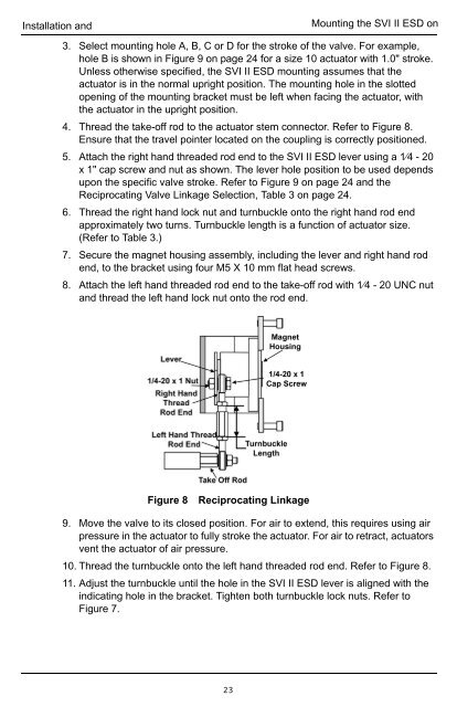
4. Thread the take-off rod to the actuator stem connector. Refer to Figure 8.<br />
Ensure that the travel pointer located on the coupling is correctly positioned.<br />
5. Attach the right hand threaded rod end to the <strong>SVI</strong> <strong>II</strong> <strong>ESD</strong> lever using a 1⁄4 - 20<br />
x 1" cap screw and nut as shown. The lever hole position to be used depends<br />
upon the specific valve stroke. Refer to Figure 9 on page 24 and the<br />
Reciprocating Valve Linkage Selection, Table 3 on page 24.<br />
6. Thread the right hand lock nut and turnbuckle onto the right hand rod end<br />
approximately two turns. Turnbuckle length is a function of actuator size.<br />
(Refer to Table 3.)<br />
7. Secure the magnet housing assembly, including the lever and right hand rod<br />
end, to the bracket using four M5 X 10 mm flat head screws.<br />
8. Attach the left hand threaded rod end to the take-off rod with 1⁄4 - 20 UNC nut<br />
and thread the left hand lock nut onto the rod end.<br />
Figure 8 Reciprocating Linkage<br />
9. Move the valve to its closed position. For air to extend, this requires using air<br />
pressure in the actuator to fully stroke the actuator. For air to retract, actuators<br />
vent the actuator of air pressure.<br />
10. Thread the turnbuckle onto the left hand threaded rod end. Refer to Figure 8.<br />
11. Adjust the turnbuckle until the hole in the <strong>SVI</strong> <strong>II</strong> <strong>ESD</strong> lever is aligned with the<br />
indicating hole in the bracket. Tighten both turnbuckle lock nuts. Refer to<br />
Figure 7.<br />
23