
You also want an ePaper? Increase the reach of your titles
YUMPU automatically turns print PDFs into web optimized ePapers that Google loves.
<strong>HIT</strong>-<strong>HY</strong> <strong>70</strong><br />
Hybrid Adhesive for Masonry<br />
Flexible, strong and reliable.<br />
<strong>Hilti</strong>. Outperform. Outlast.
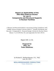
<strong>Hilti</strong> Adhesive Anchor<br />
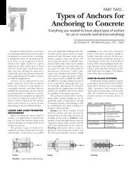
Applications<br />
• Retrofits of historic masonry<br />
buildings, including seismic<br />
retrofit of multi-wythe walls<br />
• Sign, fence or awning attachment<br />
to masonry wall or façade<br />
• Façade tie-backs to masonry<br />
structural wall<br />
• Scaffolding attachment to<br />
masonry structure<br />
• Pipe, cable tray, fixture fastening<br />
to masonry base material<br />
Outperform and Outlast<br />
Flexible, strong and reliable.<br />
<strong>HIT</strong>-<strong>HY</strong> <strong>70</strong> Masonry Adhesive<br />
Anchoring System<br />
Life just got easier with one adhesive anchoring product to<br />
solve all your masonry needs. The new <strong>Hilti</strong> <strong>HIT</strong>-<strong>HY</strong> <strong>70</strong> Masonry<br />
Adhesive Anchoring System works in a variety of masonry base<br />
materials: grout-filled block, solid brick, hollow brick, hollow<br />
CMU and multi-wythe brick walls. The improved formula and<br />
innovative composite sleeve design provides strong, reliable and<br />
easy to install fastenings.<br />
• Cures in ~ 30 minutes at <strong>70</strong>° F<br />
providing quick installation times<br />
to finish the job earlier<br />
• Achieve various embedment<br />
depths by combining mesh<br />
sleeves to custom lengths<br />
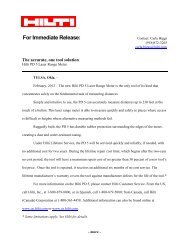
Technical Data <strong>HIT</strong>-<strong>HY</strong> <strong>70</strong><br />
Product<br />
Hybrid Urethane Methacrylate<br />
Base material temperature (grout-filled and hollow CMU, hollow brick) 23° F to 104° F (-5° C to 40° C)<br />
Base material temperature (multi-wythe) 41° F to 104° F (5° C to 40° C)<br />
Diameter range 1/4" to 3/4"<br />
Listings/Approvals • ICC-ES (International Code Council) - ESR for hollow masonry, grouted masonry and hollow brick (pending)<br />
- ESR for Un-Reinforced Masonry (URM) (pending)<br />
Package volume • Volume of <strong>HIT</strong>-<strong>HY</strong> <strong>70</strong> 11.1 fl oz/330 ml foil pack is 20.1 in 3<br />
• Volume of <strong>HIT</strong>-<strong>HY</strong> <strong>70</strong> 16.9 fl oz/500 ml foil pack is 30.5 in 3<br />
Composite Mesh Sleeves for Hollow Masonry and Brick Material<br />
Description For use with: Qty<br />
Actual<br />
Dia. (in)<br />
Length<br />
(in) Bit Dia. Item No.<br />
Mesh sleeve <strong>HIT</strong>-SC 12x50 1 1/4" dia. rods 20 0.47 1.97 1/2" 00375979<br />
Mesh sleeve <strong>HIT</strong>-SC 12x85 1 1/4" dia. rods 20 0.47 3.35 1/2" 00375980<br />
Mesh sleeve <strong>HIT</strong>-SC 16x50 1 5/16", 3/8" dia. rods and 5/16" <strong>HIT</strong>-IC rods 20 0.63 1.97 5/8" 00375981<br />
Mesh sleeve <strong>HIT</strong>-SC 16x85 1 5/16", 3/8" dia. rods and 5/16" <strong>HIT</strong>-IC rods 20 0.63 3.35 5/8" 00375982<br />
Mesh sleeve <strong>HIT</strong>-SC 18x50 1 1/2" dia. rods 20 0.71 1.97 11/16" 00360485<br />
Mesh sleeve <strong>HIT</strong>-SC 18x85 1 1/2" dia. rods 20 0.71 3.35 11/16" 00360486<br />
Mesh sleeve <strong>HIT</strong>-SC 22x50 1 5/8” dia. rods, 3/8” and 1/2” <strong>HIT</strong>-IC rods 20 0.87 1.97 7/8" 00273662<br />
Mesh sleeve <strong>HIT</strong>-SC 22x85 1 5/8” dia. rods, 3/8” and 1/2” <strong>HIT</strong>-IC rods 10 0.87 3.35 7/8" 00284511<br />
Mesh sleeve <strong>HIT</strong>-SC 26x125 2 3/4" dia. rods 20 1.02 4.92 1" 00360487<br />
Mesh sleeve <strong>HIT</strong>-SC 26x200 2 3/4" dia. rods 20 1.02 7.87 1" 00360488<br />
Internally Threaded Inserts for Hollow Masonry, Grouted Masonry and Brick Material<br />
Description For use with: Qty<br />
Bit Dia.<br />
(in)<br />
Threads<br />
per inch Item No.<br />
Internally Threaded <strong>HIT</strong>-IC 5/16" x 2" In hollow material use with <strong>HIT</strong>-SC 16 x 50 10 5/8" 18 00047945<br />
Internally Threaded <strong>HIT</strong>-IC 5/16" x 3-3/16" 3 In hollow material use with <strong>HIT</strong>-SC 16 x 85 10 5/8" 18 00047941<br />
Internally Threaded <strong>HIT</strong>-IC 3/8" x 2" In hollow material use with <strong>HIT</strong>-SC 22 x 50 10 7/8" 16 00047946<br />
Internally Threaded <strong>HIT</strong>-IC 3/8" x 3-3/16" 3 In hollow material use with <strong>HIT</strong>-SC 22 x 85 10 7/8" 16 00047942<br />
Internally Threaded <strong>HIT</strong>-IC 1/2" x 2" In hollow material use with <strong>HIT</strong>-SC 22 x 50 10 7/8" 13 00047947<br />
Internally Threaded <strong>HIT</strong>-IC 1/2" 3-3/16" 3 In hollow material use with <strong>HIT</strong>-SC 22 x 85 10 7/8" 13 00047943<br />
1<br />
2<br />
3<br />
2 <strong>Hilti</strong>, Inc. (USA) 1-800-879-8000 I www.us.hilti.com I en español 1-800-879-5000 I <strong>Hilti</strong> (Canada) Corp. 1-800-363-4458 I www.hilti.ca I <strong>HIT</strong>-<strong>HY</strong> <strong>70</strong> Submittal Information 01/12
<strong>Hilti</strong> Adhesive Anchor<br />
<strong>HIT</strong>-<strong>HY</strong> <strong>70</strong> Hybrid Adhesive for Masonry Construction<br />
1.1 Product Description<br />
1.2 Material Specifications<br />
1.3 Technical Data<br />
1.4 Installation Parameters<br />
Listings/Approvals<br />
ICC-ES (International Code Council)<br />
ESR (ICC-ES AC58) Pending<br />
ICC-ES (International Code Council)<br />
ESR (ICC-ES AC60) Pending<br />
Independent Code<br />
Evaluation<br />
IBC/IRC 2006, 2009 (ICC-ES AC58)<br />
IBC/IRC/IEBC 2006, 2009 (ICC-ES AC60)<br />
UBC/UCBC 1997 (ICC-ES AC60)<br />
LEED ® : Credit 4.1-Low Emitting Materials<br />
The Leadership in Energy and<br />
Environmental Design (LEED) Green<br />
Building Rating system is the nationally<br />
accepted benchmark for the design,<br />
construction, and operation of high<br />
performance green buildings.<br />
1.1 Product<br />
Description<br />
The <strong>Hilti</strong> <strong>HIT</strong>-<strong>HY</strong> <strong>70</strong> Adhesive Anchor<br />
System is used to anchor building<br />
components to light-, medium-, or<br />
normal-weight hollow (ungrouted) and<br />
grout-filled CMU, and hollow brick<br />
masonry*.<br />
<strong>HIT</strong>-<strong>HY</strong> <strong>70</strong> is an injectable hybrid<br />
adhesive mortar consisting of urethane<br />
methacrylate resin, hardener, cement<br />
and water. The resin and cement are<br />
separated from the hardener and water<br />
by means of a dual-cylinder foil pack<br />
attached to a manifold. Properties<br />
of cured <strong>HIT</strong>-<strong>HY</strong> <strong>70</strong> Adhesive are<br />
shown in Section 1.2. An injection<br />
nozzle with an internal mixing element<br />
is attached to the manifold, and the<br />
adhesive components are dispensed<br />
through the injection nozzle to ensure<br />
proper mixing of the separate adhesive<br />
components. The injection nozzle may<br />
be replaced to permit multiple uses of<br />
the cartridges. Only injection tools and<br />
static mixing nozzles as recommended<br />
by the manufacturer’s printed installation<br />
instructions (MPII) may be used.<br />
The <strong>Hilti</strong> <strong>HIT</strong>-<strong>HY</strong> <strong>70</strong> Adhesive Anchor<br />
Systems consists of steel all-threaded<br />
rods, steel internally threaded inserts,<br />
combi inserts, plastic-mesh screen tubes<br />
(for installation only in un-reinforced<br />
masonry (URM), hollow CMU, and<br />
hollow brick walls), and the <strong>HIT</strong>-<strong>HY</strong> <strong>70</strong><br />
Adhesive.<br />
Anchor elements: Steel all-threaded<br />
rods, steel internally threaded inserts,<br />
combi inserts, and combi inserts<br />
manufactured to meet the requirements<br />
and specifications as per Section 1.2.<br />
Plastic Mesh Screen Tubes: Screen<br />
tubes (to be used in URM, hollow<br />
CMU, or hollow brick masonry) are<br />
manufactured in a cylindrical shape, with<br />
one end closed to prevent extrusion of<br />
adhesive. The end is closed, but not<br />
sealed, to allow the use/combination<br />
of multiple screens for deeper<br />
embedments (URM). The screen tubes<br />
are manufactured with a mesh size,<br />
length, and diameter as specified by the<br />
adhesive manufacturer.<br />
* For clay tile, terracotta, and masonry outside the scope of<br />
this document, please contact <strong>Hilti</strong> Technical Services.<br />
<strong>Hilti</strong>, Inc. (USA) 1-800-879-8000 I www.us.hilti.com I en español 1-800-879-5000 I <strong>Hilti</strong> (Canada) Corp. 1-800-363-4458 I www.hilti.ca I <strong>HIT</strong>-<strong>HY</strong> <strong>70</strong> Submittal Information 01/12<br />
3
<strong>Hilti</strong> Adhesive Anchor<br />
1.2 Material Specifications<br />
Material Properties for <strong>HIT</strong>-<strong>HY</strong> <strong>70</strong> — Cured Adhesive<br />
Compressive Strength ASTM D 695/DIN 53454 7,252-10,153 psi 50-<strong>70</strong> MPa<br />
Modulus of elasticity (Compression test) ASTM D 790/DIN 53452 246,568 psi 1,<strong>70</strong>0 MPa<br />
Water Absorption ASTM D 5<strong>70</strong>/DIN 53495 3-8 % 3-8 %<br />
Electrical Resistance VDE/DIN 0303T3 4.2 · 10 11 ohm/in. 1.065 · 10 12 ohm/cm<br />
Mechanical Properties<br />
Material Specifications<br />
f y<br />
min. f u<br />
ksi (MPa) ksi (MPa)<br />
Standard HAS-E rod material meets the requirements of ISO 898 Class 5.8 58 (400) 72.5 (500)<br />
High Strength or “Super HAS” rod material meets the requirements of ASTM A 193, Grade B7 105 (724) 125 (862)<br />
Stainless HAS rod material meets the requirements of ASTM F 593 (AISI 304/316) Condition CW 65 (448) 100 (689)<br />
3/8" to 5/8"<br />
Stainless HAS rod material meets the requirements of ASTM F 593 (AISI 304/316) Condition CW 3/4" 45 (310) 85 (586)<br />
Carbon Steel HIS-N Insert confirming to DIN 10277-3 54.4 (375) 66.7 (460)<br />
Stainless Steel HIS-RN Insert conforming to DIN 10088-3 50.8 (350) 101.5 (<strong>70</strong>0)<br />
Carbon Steel <strong>HIT</strong>-IC Insert conforming to DIN 10277-3 54.4 (375) 66.7 (460)<br />
HAS Super and HAS-E Standard Nut Material meets the requirements of SAE J995 Grade 5<br />
HAS Stainless Steel Nut material meets the requirements of ASTM F 594<br />
HAS-E Carbon Steel and Stainless Steel Washers meet dimensional requirements of ANSI B18.22.1 Type A Plain<br />
HAS Stainless Steel Washers meet the requirements of AISI 304 or AISI 316 conforming to ASTM A 240<br />
HAS Super and HAS-E Standard Washers meet the requirements of ASTM F 884, HV<br />
All HAS-E and HAS Super Rods and HAS-E Standard, HIS-N inserts, nuts and washers are zinc plated to<br />
ASTM B 633 SC 1<br />
Note: Special Order steel rod material may vary from standard materials.<br />
1.3 Technical Data<br />
1, 2, 3<br />
Allowable Tension and Shear Values for Threaded Rods Based on Steel Strength<br />
Anchor<br />
Diameter<br />
in. (mm)<br />
ISO 898<br />
Class 5.8<br />
Tension lb (kN)<br />
ASTM A193 B7<br />
ASTM F 593 CW<br />
(304/316)<br />
ISO 898<br />
Class 5.8<br />
Shear lb (kN)<br />
ASTM A193 B7<br />
ASTM F 593 CW<br />
(304/316)<br />
1/4 (6.4) 1175 (5.2) 2025 (9.0) 1620 (7.2) 605 (2.7) 1040 (4.6) 835 (3.7)<br />
5/16 (7.9) 1835 (8.2) 3160 (14.1) 2530 (11.3) 945 (4.2) 1630 (7.3) 1300 (5.8)<br />
3/8 (9.5) 2640 (11.7) 4555 (20.3) 3645 (16.2) 1360 (6.1) 2345 (10.4) 1875 (8.3)<br />
1/2 (12.7) 4<strong>70</strong>0 (20.9) 8100 (36.0) 6480 (28.8) 2420 (10.8) 41<strong>70</strong> (18.6) 3335 (14.8)<br />
5/8 (15.9) 7340 (32.7) 12655 (56.3) 10125 (45.1) 3780 (16.8) 6520 (29.0) 5215 (23.2)<br />
3/4 (19.1) 105<strong>70</strong> (47.0) 18225 (81.1) 12390 (55.1) 5445 (24.2) 9390 (41.8) 6385 (28.4)<br />
1 Allowable load used in the design must be the lesser of bond values and tabulated steel values.<br />
2 The allowable tension and shear values for threaded rods to resist short term loads, such as wind or seismic, must be calculated in accordance with the appropriate IBC Sections.<br />
3 Allowable steel loads are based on allowable tension and allowable shear stresses equal to 0.33 x F u<br />
and 0.17 x F u<br />
, respectively.<br />
4 <strong>Hilti</strong>, Inc. (USA) 1-800-879-8000 I www.us.hilti.com I en español 1-800-879-5000 I <strong>Hilti</strong> (Canada) Corp. 1-800-363-4458 I www.hilti.ca I <strong>HIT</strong>-<strong>HY</strong> <strong>70</strong> Submittal Information 01/12
<strong>Hilti</strong> Adhesive Anchor<br />
1.3 Technical Data<br />
Allowable Tension Loads for Threaded Rods in the Vertical Face of<br />
1, 2, 7, 8, 9, 11, 12<br />
Grout-Filled Concrete Masonry Units<br />
Anchor<br />
Diameter,<br />
in. (mm)<br />
Embedment,<br />
in. (mm) 3<br />
Load @ c cr<br />
and s cr<br />
,<br />
lb (kN)<br />
Critical,<br />
s cr<br />
,<br />
in. (mm)<br />
3/8 (9.5) 3-3/8 (85.7) 1235 (5.5) 13.5 (342.9)<br />
Spacing 4 Edge Distance 5<br />
Minimum,<br />
s min<br />
,<br />
in. (mm)<br />
Load<br />
Reduction<br />
Factor @<br />
s min<br />
6<br />
Critical,<br />
c cr<br />
,<br />
in. (mm)<br />
0.74 12 (304.8)<br />
Minimum,<br />
c min<br />
,<br />
in. (mm)<br />
Load<br />
Reduction<br />
Factor @<br />
c min<br />
6<br />
1/2 (12.7) 4-1/2 (114.3) 2030 (9.0) 18 (457.2) 0.74 20 (508) 0.76<br />
4 (101.6)<br />
4 (101.6)<br />
5/8 (15.9) 5-5/8 (142.9) 2835 (12.6) 22.5 (571.5) 0.50 20 (508) 0.71<br />
3/4 (19.1) 6-3/4 (171.5) 3805 (16.9) 27 (685.8) 0.50 20 (508) 0.66<br />
0.80<br />
Allowable Shear Loads for Threaded Rods in the Vertical Face of<br />
1, 2, 7, 8, 9, 11, 12<br />
Grout-Filled Concrete Masonry Units<br />
Anchor<br />
Diameter,<br />
in. (mm)<br />
Embedment,<br />
in. (mm) 3<br />
Spacing 4 Edge Distance 5<br />
Load @ c cr<br />
Load<br />
and s cr<br />
,<br />
Critical, Minimum,<br />
Critical, Minimum,<br />
lb (kN) 10 s cr<br />
, s min<br />
,<br />
in. (mm)<br />
3/8 (9.5) 3-3/8 (85.7) 890 (4.0) 13.5 (342.9)<br />
in. (mm)<br />
Reduction<br />
Factor @<br />
s min<br />
6<br />
c cr<br />
,<br />
in. (mm)<br />
0.50 12 (304.8)<br />
c min<br />
,<br />
in. (mm)<br />
Load Reduction Factor<br />
@ c min<br />
6<br />
Load<br />
Perpendicular<br />
to Edge<br />
Load<br />
Parallel<br />
to Edge<br />
0.87 1.00<br />
1/2 (12.7) 4-1/2 (114.3) 1495 (6.7) 18 (457.2) 0.50 12 (304.8) 0.50 1.00<br />
4 (101.6)<br />
4 (101.6)<br />
5/8 (15.9) 5-5/8 (142.9) 2613 (11.6) 22.5 (571.5) 0.50 20 (508) 0.38 0.80<br />
3/4 (19.1) 6-3/4 (171.5) 4090 (18.2) 27 (685.8) 0.50 20 (508) 0.26 0.61<br />
1 All values are for anchors installed in fully grouted concrete masonry with minimum masonry prism strength of 1500 psi. Concrete masonry units shall be light-, medium-, or normal-weight<br />
conforming to ASTM C 90. Allowable loads are computed using a safety factor of 5.<br />
2 Anchors may be installed in any location in the face of the masonry wall (cell, bed joint, or web), except anchors must not be installed in or within one inch in any direction of a vertical (head)<br />
joint. Anchors are limited to one per masonry cell.<br />
3 Embedment depth is measured from the outside face of the concrete masonry unit.<br />
4 The critical spacing, s cr<br />
, is the anchor spacing where full load values in the Table may be used. The minimum spacing, s min<br />
, is the minimum anchor spacing for which values are available and<br />
installation is recommended. Spacing is measured from the center of one anchor to the center of an adjacent anchor.<br />
5 The critical edge distance, c cr<br />
, is the edge distance where full load values in the Table may be used. The minimum edge distance, c min<br />
, is the minimum edge distance for which values are<br />
available and installation is recommended. Edge distance is measured from the center of the anchor to the closest edge.<br />
6 Load reduction factors are multiplicative, both spacing and edge distance load reduction factors must be considered.<br />
Load values for anchors installed at less than s cr<br />
and c cr<br />
must be multiplied by the appropriate load reduction factor based on actual edge distance (c) or spacing (s).<br />
7 Linear interpolation of load values between minimum spacing (s min<br />
) and critical spacing (s cr<br />
) and between minimum edge distance (c min<br />
) and critical edge distance (c cr<br />
) is permitted.<br />
8 Concrete masonry thickness must be equal to or greater than 1.5 times the anchor embedment depth. EXCEPTION: the 5/8-inch- and the 3/4-inch-diameter anchors may be installed in<br />
minimum nominally 8-inch-thick concrete masonry.<br />
9 When using the basic load combinations in accordance with IBC Section 1605.3.1, tabulated allowable loads must not be increased for seismic or wind loading. When using the alternative<br />
basic load combinations in IBC Section 1605.3.2 that include seismic or wind loads, tabulated allowable loads may be increased by 33-1/3 percent, or the alternative basic load combinations<br />
may be reduced by a factor of 0.75.<br />
10 Allowable shear loads must be the lesser of the adjusted masonry or bond tabulated values and the steel values given in Section 1.3.<br />
11 Tabulated allowable loads shall be adjusted for increased base material temperatures in accordance with Figure 1, as applicable.<br />
Tapplied Vapplied<br />
12 For combined loading:<br />
__________ + __________ ≤1<br />
Tallowable Vallowable<br />
<strong>Hilti</strong>, Inc. (USA) 1-800-879-8000 I www.us.hilti.com I en español 1-800-879-5000 I <strong>Hilti</strong> (Canada) Corp. 1-800-363-4458 I www.hilti.ca I <strong>HIT</strong>-<strong>HY</strong> <strong>70</strong> Submittal Information 01/12<br />
5
<strong>Hilti</strong> Adhesive Anchor<br />
1.3 Technical Data<br />
Allowable Tension and Shear Loads for Threaded Rods in the Top of<br />
1, 2, 3, 4, 8<br />
Grout-Filled Concrete Masonry Units<br />
Anchor<br />
Diameter,<br />
in. (mm)<br />
Embedment,<br />
in. (mm)<br />
1/2 (12.7) 4-1/2 (114.3)<br />
5/8 (15.9) 5-5/8 (142.9)<br />
Edge<br />
Distance,<br />
in. (mm) 5, 6<br />
1-3/4 (44.5)<br />
Minimum End<br />
Distance,<br />
in. (mm)<br />
Tension Load,<br />
lb (kN)<br />
Shear Load, lb (kN) 7<br />
Load Parallel<br />
to Edge of<br />
Masonry Wall<br />
Load<br />
Perpendicular<br />
to Edge of<br />
Masonry Wall<br />
1168 (5.2) 816 (3.6) 344 (1.5)<br />
4 (101.6) 1586 (7.1) 1444 (6.4) 506 (2.3)<br />
8 (203.2)<br />
1-3/4 (44.5) 1372 (6.1) 1190 (5.3) 382 (1.7)<br />
4 (101.6) 1745 (7.8) 1824 (8.1) 654 (2.9)<br />
1 All values are for anchors installed in fully grouted concrete masonry with minimum masonry prism strength of 1500 psi. Concrete masonry units shall be light-, medium-, or normal-weight<br />
conforming to ASTM C 90. Allowable loads are computed using a safety factor of 5.<br />
2 When using the basic load combinations in accordance with IBC Section 1605.3.1, tabulated allowable loads must not be increased for seismic or wind loading. When using the alternative<br />
basic load combinations in IBC Section 1605.3.2 that include seismic or wind loads, tabulated allowable loads may be increased by 33-1/3 percent, or the alternative basic load combinations<br />
may be reduced by a factor of 0.75.<br />
3 One anchor shall be permitted to be installed in each CMU block.<br />
4 Anchors are not permitted to be installed in a head joint, flange or web of the concrete masonry unit.<br />
5 The tabulated edge distance is measured from the anchor centerline to the edge of the CMU block. (See Figure 3 (right)).<br />
6 Linear interpolation of load values between the two tabulated edge distances is permitted.<br />
7 Allowable shear loads must be the lesser of the adjusted masonry or bond tabulated values and the steel values given in Section 1.3.<br />
8 Tabulated allowable loads shall be adjusted for increased base material temperatures in accordance with Figure 1, as applicable.<br />
6 <strong>Hilti</strong>, Inc. (USA) 1-800-879-8000 I www.us.hilti.com I en español 1-800-879-5000 I <strong>Hilti</strong> (Canada) Corp. 1-800-363-4458 I www.hilti.ca I <strong>HIT</strong>-<strong>HY</strong> <strong>70</strong> Submittal Information 01/12
<strong>Hilti</strong> Adhesive Anchor<br />
1.3 Technical Data<br />
Allowable Tension Loads for HIS-N inserts in the Vertical Face of<br />
1, 2, 7, 8, 9, 11,12<br />
Grout-Filled Concrete Masonry Units<br />
Anchor<br />
Diameter,<br />
in. (mm)<br />
Embedment,<br />
in. (mm) 3<br />
Load @ c cr<br />
and s cr<br />
,<br />
lb (kN)<br />
Critical,<br />
s cr<br />
,<br />
in. (mm)<br />
Spacing 4 Edge Distance 5<br />
Minimum,<br />
s min<br />
,<br />
in. (mm)<br />
Load<br />
Reduction<br />
Factor @<br />
s min<br />
6<br />
Critical, c cr<br />
,<br />
in. (mm)<br />
Minimum,<br />
c min<br />
,<br />
in. (mm)<br />
Load<br />
Reduction<br />
Factor @<br />
c min<br />
6<br />
3/8 (9.5) 4-1/4 (108) 2072 (9.2) 17 (431.8)<br />
0.74 12 (304.8)<br />
0.82<br />
4 (101.6)<br />
4 (101.6)<br />
1/2 (12.7) 5 (127) 2<strong>70</strong>8 (12.1) 20 (508) 0.74 20 (508) 0.63<br />
Allowable Shear Loads for HIS-N inserts in the Vertical Face of<br />
1, 2, 7, 8, 9, 11,12<br />
Grout-Filled Concrete Masonry Units<br />
Anchor<br />
Diameter,<br />
in. (mm)<br />
Embedment,<br />
in. (mm) 3<br />
Spacing 4 Edge Distance 5<br />
Load @ c cr<br />
Load<br />
and s cr<br />
,<br />
Critical, Minimum,<br />
Critical, Minimum,<br />
lb (kN) 10 s cr<br />
, s min<br />
,<br />
in. (mm)<br />
in. (mm)<br />
Reduction<br />
Factor @<br />
s min<br />
6<br />
c cr<br />
,<br />
in. (mm)<br />
c min<br />
,<br />
in. (mm)<br />
Load Reduction Factor<br />
@ c min<br />
6<br />
Load<br />
Perpendicular<br />
to Edge<br />
Load<br />
Parallel<br />
to Edge<br />
3/8 (9.5) 4-1/4 (108) 1097 (4.9) 17 (431.8)<br />
0.50 12 (304.8)<br />
0.72 1.00<br />
4 (101.6)<br />
4 (101.6)<br />
1/2 (12.7) 5 (127) 2063 (9.2) 20 (508) 0.50 20 (508) 0.40 0.87<br />
1 All values are for anchors installed in fully grouted concrete masonry with minimum masonry prism strength of 1500 psi. Concrete masonry units shall be light-, medium-, or normal-weight<br />
conforming to ASTM C 90. Allowable loads are computed using a safety factor of 5.<br />
2 Anchors may be installed in any location in the face of the masonry wall (cell, bed joint, or web), except anchors must not be installed in or within one inch in any direction of a vertical (head)<br />
joint. Anchors are limited to one per masonry cell.<br />
3 Embedment depth is measured from the outside face of the concrete masonry unit.<br />
4 The critical spacing, s cr<br />
, is the anchor spacing where full load values in the Table may be used. The minimum spacing, s min<br />
, is the minimum anchor spacing for which values are available and<br />
installation is recommended. Spacing is measured from the center of one anchor to the center of an adjacent anchor.<br />
5 The critical edge distance, c cr<br />
, is the edge distance where full load values in the Table may be used. The minimum edge distance, c min<br />
, is the minimum edge distance for which values are<br />
available and installation is recommended. Edge distance is measured from the center of the anchor to the closest edge.<br />
6 Load reduction factors are multiplicative, both spacing and edge distance load reduction factors must be considered.<br />
Load values for anchors installed at less than s cr<br />
and c cr<br />
must be multiplied by the appropriate load reduction factor based on actual edge distance (c) or spacing (s).<br />
7 Linear interpolation of load values between minimum spacing (s min<br />
) and critical spacing (s cr<br />
) and between minimum edge distance (c min<br />
) and critical edge distance (c cr<br />
) is permitted.<br />
8 Concrete masonry thickness must be equal to or greater than 1.5 times the anchor embedment depth. EXCEPTION: the 5/8-inch- and the 3/4-inch-diameter anchors may be installed in<br />
minimum nominally 8-inch-thick concrete masonry.<br />
9 When using the basic load combinations in accordance with IBC Section 1605.3.1, tabulated allowable loads must not be increased for seismic or wind loading. When using the alternative<br />
basic load combinations in IBC Section 1605.3.2 that include seismic or wind loads, tabulated allowable loads may be increased by 33-1/3 percent, or the alternative basic load combinations<br />
may be reduced by a factor of 0.75.<br />
10 Allowable shear loads must be the lesser of the adjusted masonry or bond tabulated values and the steel values given in Section 1.3.<br />
11 Tabulated allowable loads shall be adjusted for increased base material temperatures in accordance with Figure 1, as applicable.<br />
Tapplied Vapplied<br />
12 For combined loading:<br />
__________ + __________ ≤1<br />
Tallowable Vallowable<br />
<strong>Hilti</strong>, Inc. (USA) 1-800-879-8000 I www.us.hilti.com I en español 1-800-879-5000 I <strong>Hilti</strong> (Canada) Corp. 1-800-363-4458 I www.hilti.ca I <strong>HIT</strong>-<strong>HY</strong> <strong>70</strong> Submittal Information 01/12<br />
7
<strong>Hilti</strong> Adhesive Anchor<br />
1.3 Technical Data<br />
Allowable Tension and Shear Loads for Threaded Rods in the<br />
1, 3, 6, 7, 9<br />
Vertical Face of Hollow Concrete Masonry Units<br />
Anchor<br />
Diameter,<br />
in. (mm)<br />
1/4 (6.4)<br />
Embedment,<br />
in. (mm) 2<br />
Tension<br />
Load,<br />
lb (kN) 4, 5<br />
215 (1.0)<br />
Minimum Edge<br />
Distance, c min<br />
,<br />
in. (mm) 6<br />
Shear Load<br />
Edge Distance 6<br />
lb (kN) 4, 8 in. (mm) in. (mm)<br />
@ c cr<br />
, Critical, c cr<br />
, Minimum, c min<br />
,<br />
355 (1.6) 4 (101.6)<br />
Load Reduction<br />
Factor @ c min<br />
5/16 (7.9) 305 (1.4) 630 (2.8) 12 (304.8) 0.73<br />
2 (50.8)<br />
4 (101.6)<br />
4 (101.6)<br />
3/8 (9.5) 390 (1.7) 640 (2.8) 12 (304.8) 0.73<br />
1/2 (12.7) 390 (1.7) 6<strong>70</strong> (3.0) 12 (304.8) 0.73<br />
1.00<br />
Allowable Tension and Shear Loads for <strong>HIT</strong>-IC Inserts in the<br />
1, 3, 6, 7, 9<br />
Vertical Face of Hollow Concrete Masonry Units<br />
Anchor Diameter,<br />
in. (mm)<br />
#14 Screw (6.4)<br />
Embedment,<br />
in. (mm) 2<br />
Tension<br />
Load,<br />
lb (kN) 4, 5<br />
190 (0.8)<br />
Minimum Edge<br />
Distance, c min<br />
,<br />
in. (mm) 6<br />
Shear<br />
Load @<br />
c cr<br />
,<br />
4, 8<br />
lb (kN)<br />
Critical, c cr<br />
,<br />
in. (mm)<br />
235 (1.0) 4 (101.6)<br />
Edge Distance 6<br />
Minimum, c min<br />
,<br />
in. (mm)<br />
Load Reduction<br />
Factor @ c min<br />
5/16 (7.9) 415 (1.8) 600 (2.7) 12 (304.8) 0.80<br />
2 (50.8)<br />
4 (101.6)<br />
4 (101.6)<br />
3/8 (9.5) 480 (2.1) 620 (2.8) 12 (304.8) 0.78<br />
1/2 (12.7) 495 (2.2) 620 (2.8) 12 (304.8) 0.75<br />
1 All values are for anchors installed in light-, medium-, or normal-weight hollow concrete masonry units conforming to ASTM C 90. Allowable loads are computed using a safety factor of 5.<br />
2 Tabulated embedment depth is the length of the plastic <strong>HIT</strong>-SC screens.<br />
3 Anchors shall be installed in the face of the hollow CMU masonry wall. A maximum of one (two) anchor loaded in shear (tension) for each cell of the hollow CMU block is allowed.<br />
4 Tabulated values are for one anchor installed in the center of the cell of the hollow CMU. Installation in other locations of the hollow CMU (mortar joints, flange or cell web) is not permitted.<br />
5 Two anchors installed in the same cell may be spaced as close as 4 inches apart without any load reduction.<br />
6 The critical edge distance, c cr<br />
, is the edge distance where full load values in the Table may be used. The minimum edge distance, c min<br />
, is the minimum edge distance for which values are available and<br />
installation is recommended. Edge distance is measured from the center of the anchor to the closest edge.<br />
7 Anchors are not recognized for resisting earthquake forces. For short-term loading due to wind forces, the allowable loads shall not be increased.<br />
8 Allowable shear loads must be the lesser of the adjusted masonry or bond tabulated values and the steel values given in Section 1.3.<br />
9 Tabulated allowable loads shall be adjusted for increased base material temperatures in accordance with Figure 1, as applicable.<br />
1.00<br />
8 <strong>Hilti</strong>, Inc. (USA) 1-800-879-8000 I www.us.hilti.com I en español 1-800-879-5000 I <strong>Hilti</strong> (Canada) Corp. 1-800-363-4458 I www.hilti.ca I <strong>HIT</strong>-<strong>HY</strong> <strong>70</strong> Submittal Information 01/12
<strong>Hilti</strong> Adhesive Anchor<br />
1.3 Technical Data<br />
Allowable Tension and Shear Loads for Threaded Rods in the<br />
1, 3, 4, 5, 6, 7<br />
Vertical Face of Hollow Brick<br />
Anchor Diameter,<br />
in. (mm)<br />
1/4 (6.4)<br />
Embedment,<br />
in. (mm) 2<br />
Tension Load,<br />
lb (kN)<br />
Shear Load,<br />
lb (kN) 8<br />
535 (2.4) 440 (2.0)<br />
5/16 (7.9) 740 (3.3) 710 (3.2)<br />
3/8 (9.5)<br />
3-1/2 (88.9)<br />
915 (4.1) 8<strong>70</strong> (3.9)<br />
1/2 (12.7) 915 (4.1) 1035 (4.6)<br />
Minimum Spacing,<br />
s min<br />
, in. (mm)<br />
8 (203.2)<br />
Minimum Edge<br />
Distance, c min<br />
,<br />
in. (mm)<br />
12 (304.8)<br />
or two complete<br />
bricks in any<br />
direction<br />
(whichever is less)<br />
Allowable Tension and Shear Loads for <strong>HIT</strong>-IC Inserts in the<br />
1, 3, 4, 5, 6, 7<br />
Vertical Face of Hollow Brick<br />
Anchor Diameter,<br />
in. (mm)<br />
Embedment,<br />
in. (mm) 2<br />
Tension Load,<br />
lb (kN)<br />
Shear Load,<br />
lb (kN) 8<br />
#14 Screw (6.4) 2 (50.8) 1<strong>70</strong> (0.8) 265 (1.2)<br />
5/16 (7.9)<br />
890 (4.0) 785 (3.5)<br />
3/8 (9.5) 3-1/2 (88.9)<br />
890 (4.0) 965 (4.3)<br />
1/2 (12.7) 1000 (4.5) 990 (4.4)<br />
Minimum Spacing,<br />
s min<br />
, in. (mm)<br />
8 (203.2)<br />
Minimum Edge<br />
Distance, c min<br />
,<br />
in. (mm)<br />
12 (304.8)<br />
or two complete<br />
bricks in any<br />
direction<br />
(whichever is less)<br />
1 All values are for anchors installed in hollow brick units conforming to ASTM C 652. Allowable loads are computed using a safety factor of 5.<br />
2 Tabulated embedment depth is the length of the plastic <strong>HIT</strong>-SC screens.<br />
3 Anchors shall be installed in the face of the red brick masonry wall.<br />
4 Tabulated values are for one anchor installed in the center of the cell of the hollow brick. Installation in other locations of the hollow brick (mortar joints, flanges or cell web) is not permitted.<br />
5 The minimum edge distance, c min<br />
, and the minimum spacing, s min<br />
, are the minimum distances for which values are available and installation is recommended. Edge distance is measured from the center<br />
of the anchor to the closest edge. Spacing is measured from the center of one anchor to the center of an adjacent anchor<br />
6 Anchors are not recognized for resisting earthquake forces. For short-term loading due to wind forces, the allowable loads shall not be increased.<br />
7 Tabulated allowable loads shall be adjusted for increased base material temperatures in accordance with Figure 1, as applicable.<br />
8 Allowable shear loads must be the lesser of the adjusted masonry or bond tabulated values and the steel values given in Section 1.2.<br />
Allowable Tension and Shear Loads for Threaded Rods in<br />
1, 3, 4, 5, 6, 7<br />
Multi-Wythe walls<br />
Anchor<br />
Diameter,<br />
in. (mm)<br />
3/8 (9.5)<br />
1/2 (12.7)<br />
5/8 (15.9)<br />
3/4 (19.1)<br />
Embedment,<br />
in. (mm) 2<br />
Tension Load,<br />
lb (kN)<br />
Shear Load,<br />
lb (kN)<br />
6 (152.4) 895 (4.0) 680 (3.0)<br />
10 (254) 1325 (5.9) 795 (3.5)<br />
6 (152.4) 895 (4.0) 1075 (4.8)<br />
10 (254) 1455 (6.5) 1115 (5.0)<br />
6 (152.4) 1025 (4.6) 1405 (6.3)<br />
10 (254) 1955 (8.7) 1445 (6.4)<br />
8 (203.2) 1575 (7.0) 1985 (8.8)<br />
13 (330.2) 2135 (9.5) 1985 (8.8)<br />
Minimum Spacing, s min<br />
,<br />
in. (mm)<br />
Minimum Edge Distance,<br />
c min<br />
, in. (mm)<br />
16 (406.4)<br />
or 2 complete bricks in any direction<br />
(whichever is greater)<br />
1 All values are based on mortar shear strength of 45 psi or greater. Allowable loads are computed using a safety factor of 5.<br />
2 Tabulated embedment depth is the length of the plastic <strong>HIT</strong>-SC screens.<br />
3 Anchors must be installed in the face of the multi-wythe URM wall. The wall must have a minimum thickness of 13 inches (3 wythes).<br />
4 Tabulated values are for one anchor installed in the center of the cell of the multi-wythe URM wall.<br />
5 The minimum edge distance, c min<br />
, and the minimum spacing, s min<br />
, are the minimum distances for which values are available and installation is recommended. Edge distance is measured from the center<br />
of the anchor to the closest edge. Spacing is measured from the center of one anchor to the center of an adjacent anchor<br />
6 No adjustment for wind or earthquake loading is permitted with the tabulated loads.<br />
7 Tabulated allowable loads shall be adjusted for increased base material temperatures in accordance with Figure 1, as applicable.<br />
<strong>Hilti</strong>, Inc. (USA) 1-800-879-8000 I www.us.hilti.com I en español 1-800-879-5000 I <strong>Hilti</strong> (Canada) Corp. 1-800-363-4458 I www.hilti.ca I <strong>HIT</strong>-<strong>HY</strong> <strong>70</strong> Submittal Information 01/12<br />
9
<strong>Hilti</strong> Adhesive Anchor<br />
1.3 Technical Data<br />
23 – 32 -5... 0<br />
10 min<br />
Influence of base material temperature on gel time, curing time, and 33 on – 41bond strength 1 ... 5 of <strong>Hilti</strong> <strong>HIT</strong>-<strong>HY</strong> 10 min <strong>70</strong><br />
42 – 50 6 ... 10<br />
7 min<br />
51 – 68 11 ... 20<br />
4 min<br />
69 – 86 21 ... 30<br />
2 min<br />
Gel Time Table (Approximate)<br />
Curing 87 – Time 104 Table 31 (Approximate)<br />
... 40<br />
1 min<br />
6 h<br />
4 h<br />
2.5 h<br />
1.5 h<br />
30 min<br />
20 min<br />
23 – 32<br />
33 – 41<br />
42 – 50<br />
51 – 68<br />
69 – 86<br />
87 – 104<br />
-5 ... 0<br />
1 ... 5<br />
6 ... 10<br />
11 ... 20<br />
21 ... 30<br />
31 ... 40<br />
10 min<br />
10 min<br />
7 min<br />
4 min<br />
2 min<br />
1 min<br />
6 h<br />
4 h<br />
2.5 h<br />
1.5 h<br />
30 min<br />
20 min<br />
41<br />
42 – 50<br />
51 – 68<br />
69 – 86<br />
87 – 104<br />
5<br />
6 ... 10<br />
11 ... 20<br />
21 ... 30<br />
31 ... 40<br />
10 min<br />
7 min<br />
4 min<br />
2 min<br />
1 min<br />
4 h<br />
2.5 h<br />
1.5 h<br />
30 min<br />
20 min<br />
41<br />
42 – 50<br />
51 – 68<br />
69 – 86<br />
87 – 104<br />
5<br />
6 ... 10<br />
11 ... 20<br />
21 ... 30<br />
31 ... 40<br />
10 min<br />
7 min<br />
4 min<br />
2 min<br />
1 min<br />
4 h<br />
2.5 h<br />
1.5 h<br />
30 min<br />
20 min<br />
Figure 1 — Influence of Temperature on Bond Strength<br />
% of published allowable load bond values<br />
Base Material Temperature, °F<br />
10 <strong>Hilti</strong>, Inc. (USA) 1-800-879-8000 I www.us.hilti.com I en español 1-800-879-5000 I <strong>Hilti</strong> (Canada) Corp. 1-800-363-4458 I www.hilti.ca I <strong>HIT</strong>-<strong>HY</strong> <strong>70</strong> Submittal Information 01/12
<strong>Hilti</strong> Adhesive Anchor<br />
1.3 Technical Data<br />
Figure 2 — Locations for <strong>HIT</strong>-<strong>HY</strong> <strong>70</strong> Anchor System in Grout-Filled Cmu (Anchor Installation is Restricted to Non-Shaded<br />
Area)<br />
Figure 3 — Edge Distances for Anchors Installed in the Vertical Face of Concrete Masonry Wall Contruction (Left); Edge<br />
and End Distances for Threaded Rods Installed in the Top of Grout-Filled CMU Masonry Wall Construction<br />
<strong>Hilti</strong>, Inc. (USA) 1-800-879-8000 I www.us.hilti.com I en español 1-800-879-5000 I <strong>Hilti</strong> (Canada) Corp. 1-800-363-4458 I www.hilti.ca I <strong>HIT</strong>-<strong>HY</strong> <strong>70</strong> Submittal Information 01/12<br />
11
<strong>Hilti</strong> Adhesive Anchor<br />
1.4 Installation Parameters<br />
Hollow CMU and Clay Brick with Holes<br />
Approximate number of trigger pulls<br />
Approximate number of trigger pulls<br />
12 <strong>Hilti</strong>, Inc. (USA) 1-800-879-8000 I www.us.hilti.com I en español 1-800-879-5000 I <strong>Hilti</strong> (Canada) Corp. 1-800-363-4458 I www.hilti.ca I <strong>HIT</strong>-<strong>HY</strong> <strong>70</strong> Submittal Information 01/12
<strong>Hilti</strong> Adhesive Anchor<br />
1.4 Installation Parameters<br />
Grout-Filled CMU<br />
Approximate number of trigger pulls<br />
Approximate number of trigger pulls<br />
Approximate number of trigger pulls<br />
<strong>Hilti</strong>, Inc. (USA) 1-800-879-8000 I www.us.hilti.com I en español 1-800-879-5000 I <strong>Hilti</strong> (Canada) Corp. 1-800-363-4458 I www.hilti.ca I <strong>HIT</strong>-<strong>HY</strong> <strong>70</strong> Submittal Information 01/12<br />
13
<strong>Hilti</strong> Adhesive Anchor<br />
1.4 Installation Parameters<br />
Solid Brick<br />
Approximate number of trigger pulls<br />
Approximate number of trigger pulls<br />
14 <strong>Hilti</strong>, Inc. (USA) 1-800-879-8000 I www.us.hilti.com I en español 1-800-879-5000 I <strong>Hilti</strong> (Canada) Corp. 1-800-363-4458 I www.hilti.ca I <strong>HIT</strong>-<strong>HY</strong> <strong>70</strong> Submittal Information 01/12
<strong>Hilti</strong> Adhesive Anchor<br />
1.4 Installation Parameters<br />
Multi-Wythe Wall<br />
Approximate number of trigger pulls<br />
Approximate number of trigger pulls<br />
Approximate number of trigger pulls<br />
<strong>Hilti</strong>, Inc. (USA) 1-800-879-8000 I www.us.hilti.com I en español 1-800-879-5000 I <strong>Hilti</strong> (Canada) Corp. 1-800-363-4458 I www.hilti.ca I <strong>HIT</strong>-<strong>HY</strong> <strong>70</strong> Submittal Information 01/12<br />
15
<strong>Hilti</strong>. Outperform. Outlast.<br />
P.O. Box 21148, Tulsa, OK 74121 • <strong>Hilti</strong>, Inc. (U.S.) 1-800-879-8000 • www.us.hilti.com • en español 1-800-879-5000 • <strong>Hilti</strong><br />
(Canada) Corp. 1-800-363-4458 www.hilti.ca • <strong>Hilti</strong> is an equal opportunity employer • <strong>Hilti</strong> is a registered trademark of <strong>Hilti</strong>, Corp.<br />
©Copyright 2012 by <strong>Hilti</strong>, Inc. (U.S.) • 01/12 • DBS<br />
The data contained in this literature was current as of the date of publication. Updates and changes may be made<br />
based on later testing. If verification is needed that the data is still current, please contact the <strong>Hilti</strong> Technical<br />
Support Specialists at 1-800-363-4458. All published load values contained in this literature represent the results<br />
of testing by <strong>Hilti</strong> or test organizations. Local base materials were used. Because of variations in materials, on-site<br />
testing is necessary to determine performance at any specific site. Laser beams represented by red lines in this<br />
publication. Printed in the United States<br />
*14001 US only