HR BOILER.pdf - Hurlcon Heating
HR BOILER.pdf - Hurlcon Heating
HR BOILER.pdf - Hurlcon Heating

You also want an ePaper? Increase the reach of your titles
YUMPU automatically turns print PDFs into web optimized ePapers that Google loves.
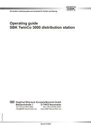
INSTALLATION AND OPERATING INSTRUCTIONS I INSTALLATION AND OPERATING INSTRUCTIONS<br />
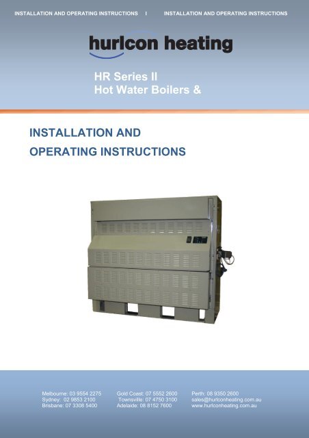
<strong>HR</strong> Series II<br />
Hot Water Boilers &<br />
INSTALLATION AND<br />
OPERATING INSTRUCTIONS<br />
Melbourne: 03 9554 2275 Gold Coast: 07 5552 2600 Perth: 08 9350 2600<br />
Sydney: 02 9853 2100 Townsville: 07 4750 3100 sales@hurlconheating.com.au<br />
Brisbane: 07 3308 5400 Adelaide: 08 8152 7600 www.hurlconheating.com.au<br />
31/05/2010
<strong>HR</strong> Series II Hot Water Boiler & Pool Heater 2
INDEX<br />
1.0 INTRODUCTION……………………………………………………………………………………….. 4<br />
1.1 NOTICE TO INSTALLERS……………………………………………………………………………. 4<br />
2.0 <strong>HR</strong> MODELS AVAILABLE…………………………………………………………………………….. 4<br />
3.0 INSTALLATION………………………………………………………………………………………… 5<br />
3.1 SAFETY RULES……………………………………………………………………………………….. 5<br />
3.2 <strong>BOILER</strong> DIMENSIONS………………………………………………………………………………… 6<br />
3.3 INDOOR INSTALLATION……………………………………………………………………………… 6<br />
3.4 VENTILATION – AIR SUPPLY TO THE <strong>BOILER</strong>…………………………………………………… 7<br />
3.5 CLEARANCES………………………………………………………………………………………….. 8<br />
3.6 ELECTRICAL CONNECTION………………………………………………………………………… 8<br />
3.7 GAS CONNECTION…………………………………………………………………………………… 8<br />
3.8 WATER CONNECTION………………………………………………………………………………. 9<br />
3.9 WATER FLOW & PUMP SELECTION……………………………………………………………… 9<br />
4.0 COMMISSIONING…………………………………………………………………………………….. 10<br />
4.1 STARTING <strong>BOILER</strong>………………………………………………………………………………….. 10<br />
4.2 TESTING BURNER PRESSURE……………………………………………………………………. 11<br />
4.3 FLOW SWITCH………………………………………………………………………………………… 11<br />
5.0 OPERATING INSTRUCTIONS………………………………………………………………………. 12<br />
5.1 CONTROL SYSTEMS - ON/OFF <strong>BOILER</strong>S………………………………………………………... 12<br />
5.2 CONTROL SYSTEMS – MODULATING <strong>BOILER</strong>S……………………………………………….. 15<br />
5.3 CONTROL SYSTEMS – POOL & SPA HEATERS………………………………………………… 17<br />
5.4 INDICATORS…………………………………………………………………………………………… 19<br />
5.5 ALARM………………………………………………………………………………………………….. 19<br />
5.6 MAIN PCB………………………………………………………………………………………………. 20<br />
6.0 GAS CONVERSION…………………………………………………………………………………… 21<br />
7.0 MAINTENANCE………………………………………………………………………………………… 21<br />
8.0 TROUBLESHOOTING…………………………………………………………………………………. 22<br />
9.0 ONE YEAR LIMITED WARRANTY…………………………………………………………………… 23<br />
<strong>HR</strong> Series II Hot Water Boiler & Pool Heater 3
INTRODUCTION<br />
Congratulations on your purchase of a <strong>Hurlcon</strong> <strong>HR</strong> Series II Hot Water Boiler. Correct installation and service of<br />
your new heating system and correct chemical maintenance of the water will ensure years of service. The <strong>HR</strong><br />
Series Boiler is a compact lightweight and efficient gas fired hot water boiler. It is equipped with features that take<br />
advantage of new technology developed exclusively by <strong>Hurlcon</strong>.<br />
The <strong>Hurlcon</strong> Boiler is a floor mounted atmospheric boiler with a built in balanced flue for outdoor installation or<br />
integral draught diverter for flued installations. The power output is controlled by an integrated electronic controller<br />
to maintain the set point water temperature over a wide load range. The electronic display tells at a glance the<br />
operational status of the boiler.<br />
Note:<br />
The appliance is not intended for use by young children or infirm person without supervision. Please ensure that<br />
young children are supervised to ensure that they do not play with the appliance.<br />
NOTICE TO INSTALLERS<br />
This is a Floor Mounted - Hot Water Boiler<br />
For use with Natural Gas or Propane Gas as per the attached data label.<br />
The information below is given to assist the installer with the installation of this range of <strong>HR</strong> 600-1800 Boilers.<br />
Please read it carefully in order to make the installation as easy as possible and to ensure the system works well<br />
and conforms to the necessary government regulations.<br />
PLEASE READ THESE INSTRUCTIONS BEFORE STARTING THE INSTALLATION.<br />
It is important that this boiler is installed and serviced as detailed in these instructions by an AUTHORISED<br />
person.<br />
This boiler is to be installed and serviced to the requirements of the<br />
Local Building, Gas, Water and Electricity Authorities.<br />
These instructions are to be held by the owner / user after installation.<br />
This appliance must be installed in accordance with the installation instructions, local gas fitting regulations, the<br />
AGA Installation Code AG 601 and any other relevant statutory authorities.<br />
Refer to data plate for details of gas type, gas consumption and burner pressure.<br />
<strong>HR</strong> MODELS AVAILABLE<br />
Model 600 800 1000 1200 1400 1600 1800<br />
Input MJ (NG) 594 792 990 1188 1386 1584 1782<br />
Output kW 136 180 225 270 316 361 406<br />
<strong>Hurlcon</strong> <strong>HR</strong> Boilers are available in 7 models and 3 control types, Modulating, On / Off and Pool Heater. Each<br />
model is covered in this booklet.<br />
<strong>HR</strong> Series II Hot Water Boiler & Pool Heater 4
INSTALLATION<br />
THIS APPLIANCE MUST BE INSTALLED BY AN AUTHORISED PERSON.<br />
Check that the boiler is the correct type and model for the installation and that there is no damage. Contact your<br />
representative or nearest <strong>Hurlcon</strong> office if there are any queries. Refer to boiler data plate for specifications of gas<br />
type, gas consumption, burner pressure and water pressure.<br />
This appliance must be installed in accordance with local regulations, A.G.A. Installation Code AG 601, AS5601<br />
and relevant electrical standards.<br />
The boiler should be installed after the pump. The water connections are located on the right hand side of the<br />
boiler. Left hand connection models are available by special order. The inlet and outlet are clearly marked. Water<br />
connections are 1 ½” or 2”mm BSP FI.<br />
The <strong>Hurlcon</strong> Boiler is fitted with a built in flow switch and will not start unless full of water and the pump is<br />
operating. The <strong>Hurlcon</strong> Boiler incorporates a balanced flue terminal and is suitable for outdoor installation. Internal<br />
models have an integral draught diverter and spigot for flue termination. Boiler clearances are detailed in Section<br />
3.5<br />
SAFETY RULES<br />
For your safety – read before lighting<br />
This appliance is equipped with an ignition device, which automatically lights the pilot. Do not try to light the pilot<br />
by hand.<br />
BEFORE OPERATING smell all around the appliance area for gas. Be sure to smell next to the floor because<br />
some gasses are heavier than air and will settle on the floor.<br />
Safety<br />
WHAT TO DO IF YOU SMELL GAS<br />
Do not try to light any gas appliance.<br />
Do not touch any electrical switch.<br />
Turn off the gas supply at the gas meter.<br />
Immediately call your gas supplier or licensed gas fitter.<br />
NOTE. Some gases are heavier than air and it may be necessary to check for gas at floor level.<br />
House keeping<br />
Do not store or use flammable liquids or chemicals near this appliance.<br />
Do not use aerosols in the vicinity of this gas appliance.<br />
Keep this appliance free of debris.<br />
WARNING:<br />
Should overheating occur or the gas supply fail to shut off, turn off the manual gas control valve to the appliance.<br />
Do not use this boiler if any part has been under water.<br />
<strong>HR</strong> Series II Hot Water Boiler & Pool Heater 5
<strong>BOILER</strong> DIMENSIONS<br />
*Indoor model shown, outdoor model supplied without flue spigot.<br />
INDOOR INSTALLATION<br />
If the <strong>HR</strong> Boiler is to be installed indoors the correct size flue must be connected. The <strong>HR</strong> series boilers have an<br />
inbuilt draught diverter so the flue can be connected directly to the outlet spigot. The top of the boiler is not<br />
designed to support the flue. Suitable support must be used.<br />
Boiler model<br />
<strong>HR</strong> 600<br />
<strong>HR</strong> 800<br />
<strong>HR</strong> 1000<br />
<strong>HR</strong> 1200<br />
<strong>HR</strong> 1400<br />
<strong>HR</strong> 1600<br />
<strong>HR</strong> 1800<br />
Flue size<br />
255 mm<br />
305 mm<br />
405 mm<br />
405 mm<br />
455 mm<br />
455 mm<br />
455 mm<br />
The flue must also be terminated with an approved gas flue cowl (not a Chinaman’s hat) 600mm above any<br />
roofline that is within 1.5 metres horizontally from the flue.<br />
<strong>HR</strong> Series II Hot Water Boiler & Pool Heater 6
VENTILATION – AIR SUPPLY TO THE <strong>BOILER</strong><br />
When installing the boiler indoors, it is imperative that an adequate supply of fresh air is provided for combustion.<br />
Failure to provide adequate ventilation voids all warranties and may be a danger to persons or property. Please<br />
refer to AS5601 / AG 601 for full details.<br />
Two permanent openings shall be provided directly to outside. The openings shall be located to ensure the<br />
distance between the top of the upper opening and the ceiling of the room or enclosure, and the distance between<br />
the bottom of the lower opening and the floor of the room or enclosure does not exceed 5% of the height of the<br />
room or enclosure.<br />
The minimum vertical dimension of any free ventilation opening shall be 6 mm.<br />
The minimum free ventilation area provided by each opening shall be:<br />
MODEL <strong>HR</strong> 600 800 1000 1200 1400 1800 1800<br />
AREA m 2 0.09 0.12 0.15 0.18 0.21 0.24 0.27<br />
The minimum free area provided by each vent can also be calculated by using the following formula, unless<br />
otherwise stated in AG 601.<br />
A =0.00015 x T<br />
Where A = Minimum free ventilation area (m 2 ) T = Total hourly input of all appliances (MJ/h)<br />
The following diagram is provided as a guide only. All flueing and installation work must be carried out by an<br />
authorized person. Flueing must conform to local regulations and to A.G.A. installation code AG 601. Care must<br />
be taken to provide the correct ventilation and correct flueing materials in close proximity to combustible surfaces.<br />
Approved gas<br />
termination cowl<br />
1500<br />
600<br />
Upper grille for fresh air<br />
ventilation<br />
Lower grille for fresh air<br />
ventilation<br />
<strong>HR</strong> Series II Hot Water Boiler & Pool Heater 7
Do not install spa blowers in the same room as a gas boiler. This is potentially dangerous to spa users.<br />
Do not store chemicals or fuel in the same room as the gas boiler. This may cause fire or explosion.<br />
Installations, which obtain air from a source other than directly from outside, must comply with AS<br />
5601/AG601.<br />
Warning: Air supply to the boiler room must not be affected by mechanical exhaust vents located in other<br />
parts of the building, such as kitchen or bathroom fans, spa blowers, etc.<br />
Mechanical exhaust vents may create a negative pressure in the boiler room that can become a hazard by<br />
asphyxiation, explosion or fire.<br />
CLEARANCES<br />
Clearances from non combustible surfaces are:<br />
Recommended<br />
Minimum<br />
Front 1000 mm 1000 mm<br />
Both sides 500 mm 200 mm<br />
Rear 500 mm 200 mm<br />
Above 1500 mm 1500 mm<br />
Combustible surfaces 500 mm minimum 500 mm minimum<br />
The boiler must be installed at least 500 mm from any combustible surface. Clearances must comply with AG 601<br />
and any local requirements.<br />
Recommended clearances are suggested for easier component removal, connections and servicing.<br />
The boiler is fitted with a plinth however this must be installed on a fireproof base.<br />
Boiler must be installed on a platform / base with a fully enclosed floor area, equal or greater than the<br />
boiler size.<br />
ELECTRICAL CONNECTION<br />
The boiler is supplied with a 3 pin plug top for connection to a 240V 10 amp supply. The boiler incorporates a<br />
240/24 VAC transformer which supplies power to the control circuit. A 24VAC 1 AMP supply is provided on the<br />
PCB for powering external devices. All equipment connected to mains power should be protected by an RCD<br />
circuit breaker. The boiler has a 1Ø 240 vac 8 amp power supply for the pump electrical connection which<br />
incorporates the pump run on timer. For bigger loads or 3Ø pumps a contactor must be fitted. 24 volt connections<br />
are provided for a remote start circuit with dry contact and run and fault contacts. These are dry contacts rated at<br />
24 vac only. There is also provision for remote alarm reset and outdoor ambient sensor (modulating models).<br />
GAS CONNECTION<br />
The gas connection is on the left side of the boiler. Check that the boiler you have been supplied is suitable for the<br />
type of installation and the gas that is available. The gas supply pressure must be between the minimum and<br />
maximum as shown on the boiler data plate. The gas connection size will be dependant on boiler model and gas<br />
type.<br />
For Natural gas appliances a regulator set to 1.13 kPa is recommended prior to the boiler.<br />
Natural<br />
pressure<br />
Propane<br />
pressure<br />
gas<br />
gas<br />
min inlet 1.1 kPa all models<br />
test point 0.85 kPa max all models<br />
max inlet 5 kPa all models<br />
min inlet 2.75 kPa all models<br />
test point 2.70 kPa max all models<br />
max inlet 5 kPa all models<br />
<strong>HR</strong> Series II Hot Water Boiler & Pool Heater 8
WATER CONNECTION<br />
The boiler comes fitted with removable screwed bronze flange connections. These are 40mm for models <strong>HR</strong>600 –<br />
<strong>HR</strong>1000 and 50mm for models <strong>HR</strong>1200 – <strong>HR</strong>1800.<br />
WATER FLOW & PUMP SELECTION<br />
The following flow rates and pressure drops should be used as a guide when selecting a pump. The <strong>HR</strong> series<br />
boiler has an integrated pump start and run on circuit capable of switching 240VAC 8 Amp. If the built in pump<br />
control circuit is not used a separate pump run on timer must be installed to run the pump on after burner<br />
shutdown to remove any residual heat from the boiler. It is also recommended in this case that the boiler start<br />
circuit be interlocked with the pump control.<br />
FLOW RATES & PRESSURE DROPS<br />
Boiler Model 600 800 1000 1200 1400 1600 1800<br />
10 Deg C Rise Litres per sec 3.44 4.56 5.71 6.86 8.00 9.15 10.3<br />
max flow rate Pressure drop kPa 8.0 13.0 17.0 24.0 29.0 35.0 36.0<br />
15 Deg C Rise Litres per sec 2.29 3.04 3.81 4.57 5.34 6.10 6.87<br />
Pressure drop kPa 3.9 7.6 10.5 13.5 18.0 24.0 26.0<br />
20 Deg C Rise Litres per sec 1.72 2.28 2.86 3.43 4.0 4.58 5.15<br />
min flow rate Pressure drop kPa 2.8 4.7 7.8 8.8 9.2 11.0 12.0<br />
The boiler must be set up to operate with a flow rate and corresponding temperature rise between 10° and 20°.<br />
<strong>HR</strong> Series II Hot Water Boiler & Pool Heater 9
COMMISSIONING<br />
STARTING <strong>BOILER</strong><br />
Ensure that all relevant documents and necessary approvals have been obtained. Make sure that the area around<br />
the boiler is clean and free of flammable materials, debris, liquids and chemicals. Ensure that the plant room<br />
ventilation is installed and free of obstruction. Check that the system is full of water and any air has been bled.<br />
1. Has the flow switch and or pressure switch fitted to the boiler been set and adjusted. The boiler will not<br />
light if the flow/pressure switch does not make.<br />
2. Visually check wires and fittings, and gas valve train.<br />
3. Check minimum* inlet supply gas pressure – adjust if required.<br />
Nat Gas 1.15 kPa<br />
Propane Gas 2.75 kPa<br />
*Dynamic pressure<br />
4. Turn off isolation valves to main gas train.<br />
5. Turn on isolation valves to pilot only. Check for leaks with soapy water along gas train.<br />
6. Start heater, allow pilot only to light. - Turn heater off when lit.<br />
7. Create a vacuum in your manometer and connect to test point on outlet of main gas valve, check negative<br />
pressure is stable. Burner isolation valve must be closed.<br />
8. Start heater - allow pilot to light. Check the main valve does not open when the pilot is lighting.<br />
Manometer pressure will change if wired incorrectly and main valve opens.<br />
9. Upon satisfactory results, with pilot going, open main gas train isolation valve approx 1/4 and allow<br />
burners to light. Should they fail to light, close valve and identify fault. Likely cause a)<br />
Minimum gas pressure is set too low (modulating models).<br />
b) Gas valves did not get power and did not open.<br />
c) Main burner test switch in off position. (located on main PC Board)<br />
On models 1200 – 1800 fitted with dual flame sense a flame fail may occur if the burners do not cross<br />
light within the allowable time. Reset the boiler and wait for the boiler to relight.<br />
10. Upon finding cause of fault restart at step 8<br />
11. Upon burners lighting open isolation valve fully.<br />
12. Leak test the complete gas valve train assembly.<br />
13. Adjust the water temperature setpoint at the temperature controller until the correct set temperature is<br />
displayed.<br />
14. Turn boiler off then on. Check that the boiler lights automatically.<br />
<strong>HR</strong> Series II Hot Water Boiler & Pool Heater 10
WARNING<br />
THESE <strong>BOILER</strong>S HAVE A HIGH GAS CONSUMPTION AND<br />
CAN CREATE LARGE EXPLOSIONS IN A VERY SHORT<br />
TIME. CARE MUST BE TAKEN AT ALL TIMES<br />
TESTING BURNER PRESSURE<br />
Set up manometer<br />
Turn boiler “OFF”.<br />
Remove screw from ⅛” brass test point located on outlet side of gas valve or on the burner manifold<br />
Connect manometer tube to test point.<br />
Turn boiler “ON” and wait for main burner to ignite.<br />
Once main burner has ignited, the manometer must indicate the nominal burner pressure listed below.<br />
(Modulating burners must be at full fire)<br />
If a separate regulator is fitted adjust as required. Some gas valves have a built in regulator that can be<br />
adjusted. See the datasheet section for correct adjustment for the type of gas valve fitted.<br />
Maximum inlet gas pressure is:<br />
Natural Gas 5.0 kPa Propane Gas 5.0 kPa<br />
Maximum burner pressure is:<br />
Model <strong>HR</strong> 600 <strong>HR</strong> 800 <strong>HR</strong> 1000 <strong>HR</strong> 1200 <strong>HR</strong> 1400 <strong>HR</strong> 1600 <strong>HR</strong> 1800<br />
Natural Gas kPa 0.85 0.85 0.85 0.85 0.85 0.85 0.85<br />
Propane Gas kPa 2.70 2.70 2.70 2.70 2.70 2.70 2.70<br />
FLOW SWITCH<br />
The <strong>Hurlcon</strong> <strong>HR</strong> Boiler has a factory fitted flow switch (pressure switch on Pool Heater models) located in<br />
the outlet manifold which allows the burner to operate only when the system is full of water and the<br />
circulating pump is operating. The flow switch paddle / pressure switch sensitivity should be set during<br />
commissioning.<br />
Air in the system may stop the boiler from lighting.<br />
<strong>HR</strong> Series II Hot Water Boiler & Pool Heater 11
OPERATING INSTRUCTIONS<br />
STOP! Read the safety rules above.<br />
Turn off electric power to appliance.<br />
This appliance is equipped with an ignition device, which automatically lights the pilot. Do not try to light<br />
the pilot by hand.<br />
Wait five minutes to clear out any gas. If you then smell gas, STOP! Refer to instructions above.<br />
Turn on power to appliance.<br />
Set thermostat to desired setting and press ON/OFF switch to ON (Genus models) and ensure that if a<br />
remote start circuit is connected it is made. The boiler will ignite in around 30 seconds<br />
If the appliance will not operate, press and release the reset switch. If the appliance still does not ignite,<br />
see trouble shooting page 22 or call your installer / service technician.<br />
CONTROL SYSTEMS - ON/OFF <strong>BOILER</strong>S<br />
ON / OFF <strong>BOILER</strong> - 3 BUTTON GENUS IV CONTROLLER<br />
HURLCON<br />
○<br />
><br />
<<br />
ON/OFF WARM COOL<br />
HURLCON<br />
DESCRIPTION<br />
The sophisticated Genus IV digital thermostat displays temperature read out, set point temperature and operating<br />
status of the boiler including any fault conditions.<br />
TEMPERATURE DISPLAY<br />
The temperature display indicates water temperature in the inlet of the boiler. Therefore the pump must<br />
be operating for an accurate water temperature to be displayed. Temperature sensing can be changed to<br />
leaving water by moving the sensor to the vacant pocket in the flow side of the header.<br />
Water temperature can be set between 55˚C - 90˚C. To select your desired water temperature press the<br />
up or down button repeatedly until the desired set temperature is reached.<br />
To prevent rapid cycling of the boiler, the thermostat has an inbuilt time delay which prevents the boiler<br />
from turning on for two minutes after the set point has been reached. If the time delay is activated, the<br />
symbol “L” will be displayed. This is part of normal operation.<br />
The Genus control thermostat also incorporates several safety features including a 100˚ C high limit<br />
function to prevent overheating. On simultaneous shut down of the circulating pump and boiler, the water<br />
within the boiler may exceed the set temperature for a short period. If the pump and boiler are restarted<br />
during this period, the thermostat will go into a standby mode and prevent the boiler from relighting until<br />
the temperature within the boiler has dropped below the set temperature.<br />
Should the thermostat fail to stop the boiler at the set point or at 100˚ C, there is a manual reset high limit<br />
thermostat designed to lock the boiler out and prevent further heating. Plus a lock out condition is<br />
indicated by the symbols F1 or F2. To reset a lock out condition, turn the power off for five seconds. The<br />
mechanical safety device may also need to be reset. To do this, raise the front access panel locate the<br />
high limit safety thermostat and press the red button. If the boiler has cooled sufficiently, a positive “click”<br />
should be heard and felt. The high limit is located on the front right of the electrical panel.<br />
<strong>HR</strong> Series II Hot Water Boiler & Pool Heater 12
GENUS IV 3 BUTTON CONTROLLER<br />
Switching differential. The temperature switching differential can be adjusted to stop short cycling. See<br />
table below for appropriate codes. (Default 5°.)<br />
°F or °C. The display can be toggled between Celsius and Fahrenheit. See table below for codes.<br />
(Default °C.)<br />
With the unit switched off, press and hold the on/off button then press the following.<br />
Button presses<br />
1 2 3 4<br />
Degrees C U D D D<br />
Degrees F U D D U<br />
5 ° differential D D D U<br />
10 ° differential D D U D<br />
15 ° differential D D U U<br />
20 ° differential D U D D<br />
U = warm button D = cool button<br />
55 – 90 DEGREE SETTING<br />
The Genus IV controller has the facility to limit the maximum setpoint. The factory default maximum is 90°. For<br />
55° maximum setpoint contact your <strong>Hurlcon</strong> representative.<br />
<strong>HR</strong> Series II Hot Water Boiler & Pool Heater 13
STATUS INDICATION<br />
Under normal running and also fault conditions the thermostat LCD will display a set of alpha numeric symbols to<br />
indicate the status of the boiler. The meaning of each symbol and action to be taken are listed as follows:<br />
SYMBOL MEANING ACTION<br />
Temp Unit has power.<br />
No action<br />
Display<br />
F0<br />
Boiler locked off, thermistor wire is<br />
disconnected or water at 0 C (freeze<br />
conditions).<br />
If water temperature reads greater than 0 C,<br />
phone for service.<br />
F1<br />
Thermostat reads greater than 100 C or<br />
thermistor short circuited.<br />
Allow water to cool, turn boiler off then on<br />
again<br />
F3 Thermistor fault Phone for service<br />
F4 Flame roll out detected Press boiler reset switch. If fault reoccurs<br />
phone for service.<br />
L Boiler locked out on time delay No action. Boiler in limit start delay for 2<br />
minutes. Turn off then on again to bypass<br />
delay.<br />
Pump operating & sufficient water flow to<br />
operate boiler<br />
No action<br />
Thermostat calling for heat operating.<br />
No action, boiler electronic Ignition should<br />
ignite in a few seconds<br />
Burner system has ignited and is operating.<br />
No action<br />
<strong>HR</strong> Series II Hot Water Boiler & Pool Heater 14
CONTROL SYSTEMS – MODULATING <strong>BOILER</strong>S<br />
MODULATING <strong>BOILER</strong> - SIEMENS RWF40 CONTROLLER<br />
Flow Temp.<br />
Manual operation<br />
Set Point Temp<br />
Control system ready<br />
Modulating valve closing<br />
Modulating valve opening<br />
6<br />
6<br />
Not used<br />
Limit Comparator<br />
Increase value button<br />
Decrease value button<br />
PGM<br />
Program set button<br />
PGM<br />
EXIT<br />
EXIT<br />
Program exit button<br />
WRF 40<br />
DESCRIPTION<br />
The sophisticated digital thermostat controller provides display of water flow temperature, set point temperature<br />
and operating status of the boiler. Adjusting the controller settings correctly will result in accurate control of the<br />
modulating function of the boiler.<br />
TEMPERATURE DISPLAY<br />
The RED upper display indicates the flow water temperature from the boiler. The lower GREEN display indicates<br />
the boiler water flow set temperature.<br />
The controller is set to <strong>Hurlcon</strong> factory default settings at the time of manufacture. These settings are suitable for a<br />
wide range of applications but may require fine tuning depending on individual project specifications and<br />
characteristics. A detailed Siemens RWF 40 product manual is available from Siemens or contact <strong>Hurlcon</strong>. This<br />
details all parameters and settings. An auto tune function is available for automatic tuning of the PID settings.<br />
When the heater is called to run the amber indicator will illuminate. The indicators may also flash<br />
indicating that the controller is increasing or decreasing the modulating valve output in accordance with its<br />
calculations. This can occur whether the burner is operating or not. The controller can be put into manual<br />
operation by pressing the EXIT button for 5 seconds. The<br />
Symbol will illuminate. Pressing the buttons will adjust the modulating valve position. Press EXIT for 5<br />
seconds to restore auto operation.<br />
To adjust the main setpoint (SP1) press the PGM button once. Use the buttons to set the desired value and<br />
press PGM to accept. Press EXIT to exit or wait until the display returns to the set value.<br />
<strong>HR</strong> Series II Hot Water Boiler & Pool Heater 15
Siemens RWF40 controller program standard settings<br />
To access press PRG<br />
Process data.<br />
Parameter Display Actual<br />
Settings<br />
Factory<br />
Setting<br />
Setpoint 1 * SP1 80<br />
Setpoint 2 (optional) * SP2 0<br />
Digital Setpoint Shift (optional) * Dsp 0<br />
Outside Temperature (optional)<br />
Predefinition of external setpoint *<br />
To access press and hold PRG for 10 seconds<br />
tA<br />
SPE<br />
Parameter Level.<br />
Parameter Display Factory<br />
Setting<br />
Limit value of limit comparator * AL 20<br />
Switching differential for limit comparator * HySt 0<br />
Proportional band * Pb.1 20<br />
Derivative time dt 30<br />
Integral action time rt 120<br />
Contact spacing * db 2<br />
Actuator running time tt 40<br />
Switch-on threshold burner / stage II * H y S 1 -5<br />
Switch-off threshold stage II * H y S 2 0<br />
Upper switch-off threshold * H y S 3 5<br />
Response threshold q 0<br />
<strong>Heating</strong> curve slope H 4<br />
Parallel displacement * P 0<br />
To access press and hold PRG for 10 seconds<br />
Configuration Level.<br />
Parameter Display Factory<br />
Setting<br />
Analog input 1, 2 & 3 setpoint changeover / shift C111 9030<br />
Limit comparator: controller type: setpoint 1 locking C112 0010<br />
Unit address decimal place / unit, signal for out-ofrange<br />
C113 0100<br />
Measurement range start analog input 1 * SCL 0<br />
Measurement range end analog input 1 * SCH 100<br />
Measurement range start analog input 2 * SCL2 0<br />
Measurement range end analog input 2 * SCH2 0<br />
Lower setpoint limit * SPL 50<br />
Upper setpoint limit * SPH 80<br />
Actual value correction, analog input 1 * OFF1 0<br />
Actual value correction, analog input 2 * OFF2 0<br />
Actual value correction, analog input 3 * OFF3 0<br />
Filter time constant for digital filter, analog input 1 DF1 1<br />
For OUTDOOR AMBIENT TEMP control refer to wiring diagram.<br />
For NIGHT SETBACK connect D2 and Ground on RWF40 to a time clock or similar dry contact.<br />
<strong>HR</strong> Series II Hot Water Boiler & Pool Heater 16
CONTROL SYSTEMS – POOL & SPA HEATERS<br />
POOL & SPA HEATER - 4 BUTTON GENUS IV CONTROLLER<br />
HURLCON<br />
○<br />
I<br />
><br />
<<br />
ON/OFF POOL/SPA WARM COOL<br />
HURLCON<br />
DESCRIPTION<br />
The sophisticated Genus IV digital thermostat displays temperature read out, set point temperature and operating<br />
status of the boiler including any fault conditions.<br />
TEMPERATURE DISPLAY<br />
The temperature display indicates water temperature in the inlet of the heater. Therefore the pump must be<br />
operating for an accurate pool or spa water temperature to be displayed.<br />
Comfortable pool temperature is between 26˚C and 30˚C. To select your desired temperature press the up or<br />
down button repeatedly until the desired temperature is reached.<br />
To prevent rapid cycling of the heater, the thermostat has an inbuilt time delay which prevents the heater from<br />
turning on for two minutes after the set point has been reached. If the time delay is activated, the symbol “L” will<br />
be displayed. This is part of normal operation.<br />
The thermostat can be set to temperatures between 10˚C and 40˚C. On simultaneous shut down of the circulating<br />
pump and heater, the water within the heater may exceed 45˚C for a short period. If the pump and heater are<br />
restarted during this period, the thermostat will go into a standby mode and prevent the heater from relighting until<br />
the temperature within the heater has dropped below the set temperature.<br />
Should the thermostat fail to stop the heater at the set point or at 40˚C, there are three temperature limiting safety<br />
devices designed to lock the heater out and prevent further heating. A lock out condition is indicated by the<br />
symbols F1 or F2. To reset a lock out condition, turn the power off for five seconds. For an F2 fault it may be<br />
necessary to reset the high limit thermostat. The high limit is located behind the front access panel on the front of<br />
the electrical panel to the right..<br />
<strong>HR</strong> Series II Hot Water Boiler & Pool Heater 17
STATUS INDICATION<br />
Under normal running and also fault conditions the thermostat display will indicate a set of alpha numeric symbols<br />
to indicate the status of the boiler. The meaning of each symbol and action to be taken are listed as follows:<br />
SYMBOL MEANING ACTION<br />
Temp Unit has power.<br />
No action<br />
Display<br />
F0 Boiler locked off, thermistor wire is<br />
disconnected or water at 0 C (freeze<br />
conditions).<br />
F1 Thermostat reads greater than 100 C or<br />
thermistor short circuited.<br />
F3 Thermistor fault Phone for service<br />
If water temperature reads greater than 0 C,<br />
phone for service.<br />
Allow water to cool, turn boiler off then on<br />
again<br />
F4 Flame roll out detected Press boiler reset switch. If fault reoccurs<br />
phone for service.<br />
L Heater locked out on time delay No action. Boiler in limit start delay for 2<br />
minutes. Turn off then on again to bypass<br />
delay.<br />
Pump operating & sufficient water<br />
flow/pressure to operate heater<br />
No action<br />
Thermostat calling for heat operating.<br />
No action, boiler electronic Ignition should<br />
ignite in a few seconds<br />
Burner system has ignited and is operating.<br />
No action<br />
<strong>HR</strong> Series II Hot Water Boiler & Pool Heater 18
INDICATORS<br />
As well as the individual temperature controls all <strong>Hurlcon</strong> <strong>HR</strong> models have a series of LED indicators on the front<br />
panel.<br />
Green LED indicators for<br />
Power<br />
External call<br />
Water flow / pressure<br />
Burner lit<br />
Red LED indicators for<br />
High limit fault<br />
Flame fail fault<br />
Flame roll out fault<br />
Alarm mute and fault reset buttons are located below the led indicators. A high limit fault will also require the high<br />
limit safety thermostat to be reset located on the front of the main electrical panel.<br />
For diagnostics during service LED’s on the main PCB indicate high limit, flow, pressure, remote start and pump<br />
status all visible with the front panel elevated and electrical cover removed.<br />
ALARM<br />
The <strong>HR</strong> heater has a built in alarm. The onboard piezo alarm can be enabled / disabled with the jumper located<br />
on the main PCB. The alarm mute is on the front panel.<br />
<strong>HR</strong> Series II Hot Water Boiler & Pool Heater 19
MAIN PCB<br />
F1<br />
F2<br />
F3<br />
F4<br />
F5<br />
MAINS FUSE 10 AMP SLOW BLOW 240VAC.<br />
MAINS FUSE 1 AMP 24VAC.<br />
LGB CONTROLLER FUSE 2 AMP 240VAC<br />
PUMP FUSE 8 AMP SLOW BLOW 240VAC<br />
USER OUTPUT 1 AMP 24VAC<br />
<strong>HR</strong> Series II Hot Water Boiler & Pool Heater 20
GAS CONVERSION<br />
Ensure that the valve train will pass the required gas volume.<br />
Turn off gas supply to unit.<br />
Turn off power supply to pump and boiler.<br />
Remove front access panel<br />
Disconnect gas supply from gas valve.<br />
Loosen the bolt at each end of the manifold tube securing burner assembly to the combustion chamber.<br />
Disconnect wiring from gas valves and slide complete burner tray out through the access opening.<br />
Remove burner injectors and replace with desired gas type injectors.<br />
Remove pilot burner and change pilot injector to desired gas type.<br />
Refer to the gas valve instructions in data sheet section to change the spring range.<br />
Re-install burner assembly and reconnect gas supply.<br />
Check gas system for leaks.<br />
Commence lighting procedure as described above.<br />
Adjust burner pressure as described in the commissioning section.<br />
MAINTENANCE<br />
All service, maintenance and commissioning of these appliances should be carried out by suitably<br />
qualified and licensed personnel.<br />
Routine maintenance can extend the life of the appliance. <strong>Hurlcon</strong> recommends regular routine maintenance<br />
performed at least annually. Equipment installed in harsh environments or with extreme workloads may require<br />
maintenance more often.<br />
Annual service procedure.<br />
Isolate services as required.<br />
Clear and remove any dust and debris or inappropriate material from around the appliance and its immediate area.<br />
Remove access covers and inspect for debris, clean as required.<br />
Isolate and disconnect the gas train and electrical connections to facilitate burner tray removal.<br />
Remove the burner tray.<br />
Clean main burner injectors and burners as required.<br />
Dismantle and clean pilot assemblies, including injectors.<br />
Clean and re-align flame rods.<br />
Inspect the combustion chamber.<br />
Inspect the heat exchanger for signs of damage and blockage, clean tube fins if required.<br />
Inspect tube/header connection point for signs of water leakage.<br />
Manually operate pressure relief valve to check that the drain is clear and the valve reseats.<br />
Refit burner tray and reconnect gas train and electrical connections.<br />
Leak test the gas train.<br />
Replace all access covers<br />
Check all air vents and louvres, clean as required.<br />
Restore services as required.<br />
Recommission unit, check settings and prove the operation of all safety devices.<br />
Check and monitor the operation of the appliance through several cycles or for as long as is practical.<br />
Ensure temperature controller settings are returned to normal.<br />
<strong>HR</strong> Series II Hot Water Boiler & Pool Heater 21
TROUBLESHOOTING<br />
Access to the electrical panel should be by suitably qualified personnel only, however these basic chcks may help<br />
if the boiler is not running or if the boiler will not light:<br />
Is the 240 volt power supply on and is the power indicator and temperature controller on?<br />
Check the supply and or mains fuse on PCB.<br />
Is the temperature controller turned on and the actual water temp below setpoint?<br />
Turn on controller and raise setpoint.<br />
Is the high limit safety tripped?<br />
Reset button located on the front of the electrical panel.<br />
Has the unit flame failed?<br />
Press the reset button on the front panel. Check the gas supply is on and available.<br />
Has the unit had a flame roll out?<br />
Check the area around the roll out sensor for damage and press the reset button on the front panel.<br />
Is the external heating call made?<br />
Check time clock, remote thermostat or BMS system as required.<br />
Is the flow indicator on?<br />
Check that pump is running and flow switch / pressure switch is made.<br />
Is the 24 volt control fuse ok?<br />
Check F2<br />
Does the boiler begin ignition?<br />
Check for parasitic flame. Check that the LGB controller indicator is rotating and F3 is ok.<br />
Is the pilot lighting?<br />
Check pilot solenoid opens, the ignition module has power and the ignitor sparks.<br />
If the boiler cannot be made to perform correctly, please contact <strong>Hurlcon</strong> Service<br />
on freecall 1300 727 116 or your installer / service contractor.<br />
<strong>HR</strong> Series II Hot Water Boiler & Pool Heater 22
ONE YEAR LIMITED WARRANTY<br />
GENERAL CONDITIONS<br />
<strong>Hurlcon</strong> cover your boiler with a limited 1 year warranty against defective materials and workmanship from the date<br />
of purchase (plus 30 days to allow for installation). The heat exchanger, including headers are covered by a five<br />
year warranty (plus 30 days to allow for installation). Proof of purchase date must be provided in order to<br />
substantiate warranty claim.<br />
The warranty does not include in field labour costs unless purchased separately. Any costs for transport of faulty<br />
or replacement parts, removal or reinstallation are the owner’s responsibility.<br />
<strong>Hurlcon</strong> assumes no liability for consequential damages of any kind.<br />
Periodic maintenance of your boiler is recommended, see page 20.<br />
LIMITATIONS<br />
All warranties only apply if the boiler is installed and operated in complete compliance with the installation and<br />
operating instructions. The warranty shall not apply to any boilers or parts that have been subject to accident,<br />
negligence, alteration, abuse or misuse.<br />
ADDITIONAL WARRANTY EXCLUSIONS:<br />
This warranty does not cover failures or malfunctions resulting from:<br />
Failure to properly install, operate or maintain the boiler in accordance with our printed instructions<br />
provided.<br />
Abuse, alteration, accident, fire, flood and the like. Examples of misuse or neglect include, but are not<br />
limited to, physical damage from external force, not following installation instructions, leaving door off for<br />
extended periods of time, inappropriate application of the boiler, etc.<br />
Scaling, freezing, or other conditions causing an inadequate water circulation.<br />
Incorrect gas pressure or gas supply.<br />
Incorrect or excessive flow rate of water.<br />
Failing to correctly bleed the water system of air.<br />
Chemical contamination of combustion air or use of chemical additives to the water.<br />
No person is authorised to make any warranties on <strong>Hurlcon</strong>’s behalf. To place a service call, contact <strong>Hurlcon</strong><br />
Service on freecall 1300 727 116.<br />
<strong>HR</strong> Series II Hot Water Boiler & Pool Heater 23