HR BOILER.pdf - Hurlcon Heating
HR BOILER.pdf - Hurlcon Heating
HR BOILER.pdf - Hurlcon Heating

Create successful ePaper yourself
Turn your PDF publications into a flip-book with our unique Google optimized e-Paper software.
Do not install spa blowers in the same room as a gas boiler. This is potentially dangerous to spa users.<br />
Do not store chemicals or fuel in the same room as the gas boiler. This may cause fire or explosion.<br />
Installations, which obtain air from a source other than directly from outside, must comply with AS<br />
5601/AG601.<br />
Warning: Air supply to the boiler room must not be affected by mechanical exhaust vents located in other<br />
parts of the building, such as kitchen or bathroom fans, spa blowers, etc.<br />
Mechanical exhaust vents may create a negative pressure in the boiler room that can become a hazard by<br />
asphyxiation, explosion or fire.<br />
CLEARANCES<br />
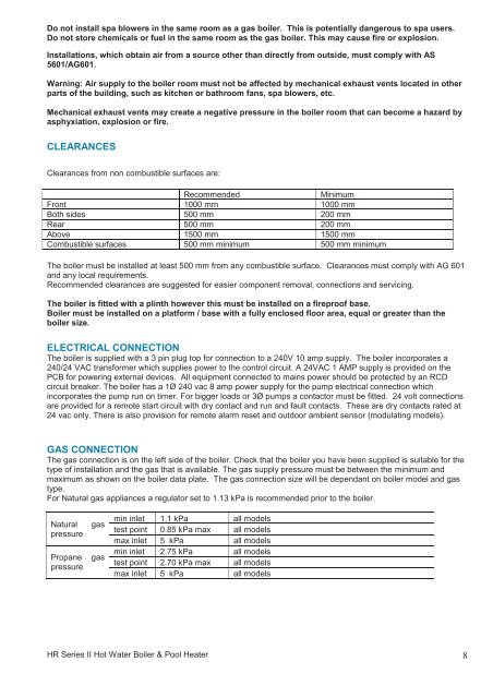
Clearances from non combustible surfaces are:<br />
Recommended<br />
Minimum<br />
Front 1000 mm 1000 mm<br />
Both sides 500 mm 200 mm<br />
Rear 500 mm 200 mm<br />
Above 1500 mm 1500 mm<br />
Combustible surfaces 500 mm minimum 500 mm minimum<br />
The boiler must be installed at least 500 mm from any combustible surface. Clearances must comply with AG 601<br />
and any local requirements.<br />
Recommended clearances are suggested for easier component removal, connections and servicing.<br />
The boiler is fitted with a plinth however this must be installed on a fireproof base.<br />
Boiler must be installed on a platform / base with a fully enclosed floor area, equal or greater than the<br />
boiler size.<br />
ELECTRICAL CONNECTION<br />
The boiler is supplied with a 3 pin plug top for connection to a 240V 10 amp supply. The boiler incorporates a<br />
240/24 VAC transformer which supplies power to the control circuit. A 24VAC 1 AMP supply is provided on the<br />
PCB for powering external devices. All equipment connected to mains power should be protected by an RCD<br />
circuit breaker. The boiler has a 1Ø 240 vac 8 amp power supply for the pump electrical connection which<br />
incorporates the pump run on timer. For bigger loads or 3Ø pumps a contactor must be fitted. 24 volt connections<br />
are provided for a remote start circuit with dry contact and run and fault contacts. These are dry contacts rated at<br />
24 vac only. There is also provision for remote alarm reset and outdoor ambient sensor (modulating models).<br />
GAS CONNECTION<br />
The gas connection is on the left side of the boiler. Check that the boiler you have been supplied is suitable for the<br />
type of installation and the gas that is available. The gas supply pressure must be between the minimum and<br />
maximum as shown on the boiler data plate. The gas connection size will be dependant on boiler model and gas<br />
type.<br />
For Natural gas appliances a regulator set to 1.13 kPa is recommended prior to the boiler.<br />
Natural<br />
pressure<br />
Propane<br />
pressure<br />
gas<br />
gas<br />
min inlet 1.1 kPa all models<br />
test point 0.85 kPa max all models<br />
max inlet 5 kPa all models<br />
min inlet 2.75 kPa all models<br />
test point 2.70 kPa max all models<br />
max inlet 5 kPa all models<br />
<strong>HR</strong> Series II Hot Water Boiler & Pool Heater 8