Manual_M50LTAT-52 - Auto Service Praxis
Manual_M50LTAT-52 - Auto Service Praxis
Manual_M50LTAT-52 - Auto Service Praxis

You also want an ePaper? Increase the reach of your titles
YUMPU automatically turns print PDFs into web optimized ePapers that Google loves.
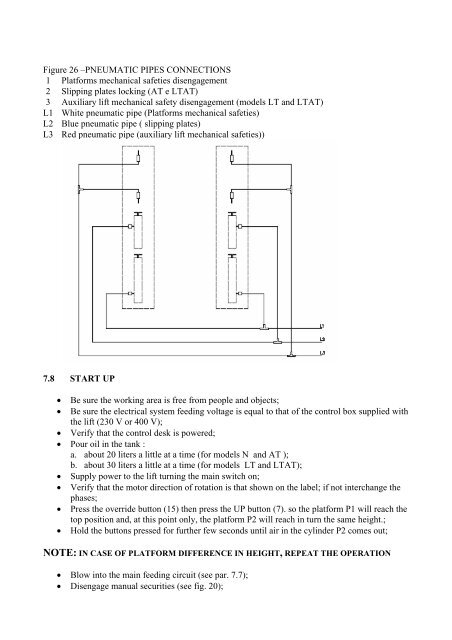
Figure 26 –PNEUMATIC PIPES CONNECTIONS<br />
1 Platforms mechanical safeties disengagement<br />
2 Slipping plates locking (AT e LTAT)<br />
3 Auxiliary lift mechanical safety disengagement (models LT and LTAT)<br />
L1 White pneumatic pipe (Platforms mechanical safeties)<br />
L2 Blue pneumatic pipe ( slipping plates)<br />
L3 Red pneumatic pipe (auxiliary lift mechanical safeties))<br />
7.8 START UP<br />
• Be sure the working area is free from people and objects;<br />
• Be sure the electrical system feeding voltage is equal to that of the control box supplied with<br />
the lift (230 V or 400 V);<br />
• Verify that the control desk is powered;<br />
• Pour oil in the tank :<br />
a. about 20 liters a little at a time (for models N and AT );<br />
b. about 30 liters a little at a time (for models LT and LTAT);<br />
• Supply power to the lift turning the main switch on;<br />
• Verify that the motor direction of rotation is that shown on the label; if not interchange the<br />
phases;<br />
• Press the override button (15) then press the UP button (7). so the platform P1 will reach the<br />
top position and, at this point only, the platform P2 will reach in turn the same height.;<br />
• Hold the buttons pressed for further few seconds until air in the cylinder P2 comes out;<br />
NOTE: IN CASE OF PLATFORM DIFFERENCE IN HEIGHT, REPEAT THE OPERATION<br />
• Blow into the main feeding circuit (see par. 7.7);<br />
• Disengage manual securities (see fig. 20);