Manual_M50LTAT-52 - Auto Service Praxis
Manual_M50LTAT-52 - Auto Service Praxis
Manual_M50LTAT-52 - Auto Service Praxis

Create successful ePaper yourself
Turn your PDF publications into a flip-book with our unique Google optimized e-Paper software.
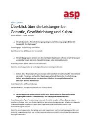
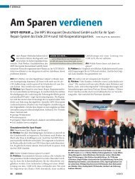
7.11.2 ADJUSTMENT OF SAFETY HEIGHT LIMIT SWITCH<br />
Screen the photocell (if the lift is in hole, raise the lift up to an height of about 150 mm) by pressing<br />
UP button (7): the lift will raise and stop at the safety height (about 400 mm).<br />
If this has not happened, adjust the limit switch<br />
as follows:<br />
• By pressing Up button (7), raise the lift<br />
to a height of 400 mm;<br />
• Loosen dowels (1) which lock the cam<br />
(2) between the arms of platform P1;<br />
• Turn the cam (2) until the limit switch<br />
detects it<br />
• Tighten the dowels (1) properly<br />
In case the limit switch does not detect the cam ,<br />
adjust it as follow:<br />
• Loosen nuts (3) and move the sensor (4)<br />
towards the cam (2) at a distance of 1 to<br />
Fig. 28<br />
3 mm.<br />
• Tighten nuts (3);<br />
N.B. PLATFORMS CANNOT BE AUTOLEVELED IF THE SAFETY HEIGHT<br />
LIMIT SWITCH IS NOT PROPERLY ADJUSTED.<br />
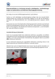
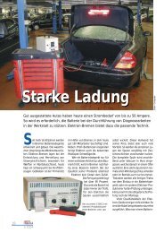
7.11.3 ADJUSTMENT OF PLATFORM AUTO-LEVELING LIMIT SWITCH<br />
With the lift on the ground, press the safety UP button, and hold it pressed to verify , on th eprnted<br />
circuit board, the proper operation of relay K4, if the correspondent light is switched on the autoleveling<br />
sensor of platform P2 works properly.<br />
With the lift in lowest position ,press final lowering button, and check on printed circuit board the<br />
relay K4 works properly. f the correspondent led is switched on the auto leveling sensor of platform<br />
P1 works properly<br />
If this has not happened, adjust the limit switch<br />
as follows:<br />
• verify the steel sheet (1) orientation with<br />
the limit switch (3);<br />
• loosen the nuts (3) of the proximity pick<br />
up (2) and adjust it at a distance between<br />
1 and 3 mm from the lamination (1);<br />
• tighten nuts (3).<br />
Fig. 29