Manual_M50LTAT-52 - Auto Service Praxis
Manual_M50LTAT-52 - Auto Service Praxis
Manual_M50LTAT-52 - Auto Service Praxis

You also want an ePaper? Increase the reach of your titles
YUMPU automatically turns print PDFs into web optimized ePapers that Google loves.
move it towards the cam (3) at a<br />
distance of 1 to 3 mm;<br />
• tighten the nuts properly<br />
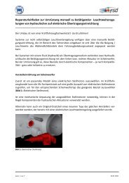
7.11.7 AUXILIARY LIFT MAX HEIGHT LIMIT SWITCH ADJUSTMENT (rif. Figure 29)<br />
With the lift-table operating, press Up button (7) and check the lift stops at 450 mm height.<br />
If this does not happen ad just the limit switch as<br />
follow (installed on platform P2) :<br />
• With the lift-table operating, press Up<br />
button (7) and raise it at a height of 450<br />
mm from lift platform; if the limit switch<br />
operates before such height, press the UP<br />
button (7) and the exclusion button (15)<br />
simultaneously.;<br />
• loosen dowels which fix the cam to the<br />
arm and turn it until the limit switch<br />
detects it presence;<br />
• tighten the dowels properly<br />
Fig.33<br />
if the limit switch does not detect the cam, ad<br />
just it as follow:<br />
• loosen nuts (2) of sensor (1), installed<br />
on external arm of auxiliary lift P2, and<br />
move it towards the cam (3) at a<br />
distance of 1 to 3 mm;<br />
• tighten the nuts properly<br />
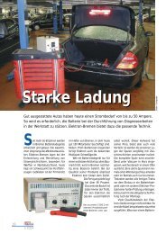
7.11.8 WORKING POSITION LIMIT SWITCH ADJUSTMENT<br />
Le posizioni di lavoro vengono regolate dalla casa costruttrice ma possono essere cambiate a<br />
seconda delle necessità dell’utilizzatore nel campo tra l’altezza minima e massima<br />
When working position buttons (13) and (14) are<br />
pressed, the platform reach max height without<br />
stopping at any intermediate height, the limit<br />
switches must be adjusted as follow:<br />
• raise the lift to 1 st working position by<br />
pressing correspondent button.;<br />
• loosen dowels (4) which fix the cam (3) to<br />
the arms of the platform P1 and turn cam<br />
(3) until the sensor detects it, and<br />
correspondent led on display switches on ;<br />
• tighten dowels properly<br />
if the limit switch does not detect the cam, ad just<br />
Fig.34<br />
it as follow:<br />
• loosen nuts (1) of sensor (2), and move it<br />
towards the cam (3) at a distance of 1 to 3<br />
mm;<br />
• tighten the nuts properly<br />
Repeat the same operation to set 2 nd working position limit switch