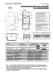
Installation and operating instructions - Haas + Sohn
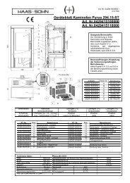
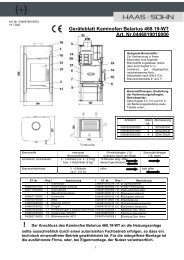
Installation and operating instructions - Haas + Sohn
Installation and operating instructions - Haas + Sohn

Create successful ePaper yourself
Turn your PDF publications into a flip-book with our unique Google optimized e-Paper software.
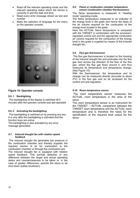
Read off the relevant <strong>operating</strong> mode <strong>and</strong> the<br />
relevant <strong>operating</strong> status which the device is<br />
currently in <strong>and</strong> the date <strong>and</strong> time<br />
Read every error message shown as text <strong>and</strong><br />
number<br />
Make the selection of language for the menu<br />
on the operator console.<br />
9.8. Flame or combustion chamber temperature<br />
sensor (combustion chamber thermosensor)<br />
The flame temperature is measured in “Heating<br />
mode” <strong>operating</strong> mode.<br />
The flame temperature measured is an indicator of<br />
the energy level in the grate <strong>and</strong> hence the basis of<br />
the air volume required for the combustion of the<br />
energy level located in the grate.<br />
Here the ACTUAL flame temperature is compared<br />
with the TARGET in combination with the processorregulated<br />
control unit <strong>and</strong> the appropriate combustion<br />
air volume required for the combustion of the energy<br />
level in the grate is supplied by means of the induced<br />
draught fan.<br />
9.9. Flue gas thermosensor<br />
The flue gas thermosensor is located on the housing<br />
of the induced draught fan <strong>and</strong> protrudes into the flue<br />
gas duct across the direction of the flow of the flue<br />
gas, where the flue gas flows around it, <strong>and</strong> thus<br />
measures its temperature <strong>and</strong> temperature change.<br />
(See Figure 10).<br />
With the thermosensor, the temperature <strong>and</strong> its<br />
change can be measured directly (accurate to about<br />
2ºC) in the flue gas <strong>and</strong> so be accessed for the<br />
control unit <strong>and</strong> regulation.<br />
Figure 15: Operator console<br />
9.6..1 Backlighting<br />
The backlighting of the display is switched off 5<br />
minutes after the operator console was last operated.<br />
9.6..2 Activating the backlighting<br />
The backlighting is switched on by pressing any key.<br />
It is only after the backlighting is activated that the<br />
function keys are active.<br />
The backlighting is also activated by any error<br />
message generated.<br />
9.10. Room temperature sensor<br />
The room temperature sensor measures the<br />
ACTUAL room temperature in the area of the<br />
stove.<br />
The room temperature sensor is an instrument for<br />
the TARGET – ACTUAL comparison between the<br />
TARGET room temperature <strong>and</strong> the ACTUAL room<br />
temperature <strong>and</strong> is therefore the basis for the<br />
specification of the required heat output for the<br />
stove.<br />
9.7. Induced draught fan with rotation speed<br />
feedback<br />
The induced draught fan generates low pressure in<br />
the combustion chamber <strong>and</strong> thereby supplies the<br />
required volume of air for combustion to the<br />
combustion chamber or through the combustion pot.<br />
The induced draught fan is equipped with rotation<br />
speed feedback. This permits detection of any<br />
difference between the target <strong>and</strong> actual <strong>operating</strong><br />
status <strong>and</strong> countermeasures to be taken or, in the<br />
case of greater differences, permits the stove to be<br />
shut down (safety shutdown).<br />
20