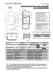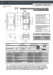
Installation and operating instructions - Haas + Sohn
Installation and operating instructions - Haas + Sohn
Installation and operating instructions - Haas + Sohn

You also want an ePaper? Increase the reach of your titles
YUMPU automatically turns print PDFs into web optimized ePapers that Google loves.
5. The pellet stove’s <strong>operating</strong> statuses:<br />
The operation of the pellet stove is characterised by 8<br />
<strong>operating</strong> statuses:<br />
The ignition phase begins if the current room<br />
temperature falls below the set target temperature by<br />
1ºC <strong>and</strong> the stove has cooled down to a temperature of<br />
below 70C°.<br />
5.1. Ignition phase<br />
In the “Ignition phase” the grate is filled with a precisely<br />
defined quantity of fuel <strong>and</strong> this quantity of fuel is ignited<br />
with a glow igniter.<br />
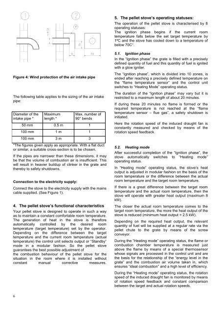
Figure 4: Wind protection of the air intake pipe<br />
The following table applies to the sizing of the air intake<br />
pipe:<br />
Diameter of the<br />
intake pipe *<br />
Maximum<br />
length *<br />
Max. number of<br />
90° bends<br />
50 mm 0.5 m 1<br />
100 mm 1 m 1<br />
The “Ignition phase”, which is divided into 10 zones, is<br />
ended after reaching a precisely defined temperature on<br />
the “flame temperature sensor” <strong>and</strong> the control unit<br />
switches to “Heating Mode” <strong>operating</strong> status.<br />
The duration of the “Ignition phase” may vary but it is<br />
restricted to a maximum length of about 20 minutes.<br />
If during these 20 minutes no flame is formed or the<br />
required temperature is not reached at the “flame<br />
temperature sensor – flue gas”, a safety shutdown is<br />
initiated.<br />
Here the rotation speed of the induced draught fan is<br />
constantly measured <strong>and</strong> checked by means of the<br />
rotation speed feedback.<br />
100 mm 3 m 3<br />
*The figures given apply as appropriate. With a flat duct<br />
or similar, a suitable cross-section is to be chosen.<br />
If the pipes are narrower than these dimensions, it may<br />
be that the volume of combustion air is insufficient. This<br />
will result in heavier buildup of clinker in the grate <strong>and</strong><br />
thereby to safety shutdowns.<br />
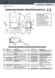
Connection to the electricity supply:<br />
Connect the stove to the electricity supply with the mains<br />
cable supplied. (See Figure 1).<br />
4. The pellet stove’s functional characteristics<br />
Your pellet stove is designed to operate in such a way<br />
as to maintain a constant comfortable room temperature.<br />
The generation of heat in the stove is therefore<br />
automatically controlled by the desired room<br />
temperature (target temperature) set by the operator.<br />
Depending on the difference between the target<br />
temperature <strong>and</strong> the current room temperature (actual<br />
temperature) the control unit selects output or “St<strong>and</strong>by”<br />
mode in a modular fashion. So the pellet stove<br />
guarantees the best possible adjustment of<br />
the combustion behaviour of the pellet stove for the<br />
situation in the room where it is installed without<br />
constant manual corrective measures.<br />
5.2. Heating mode<br />
After successful completion of the “Ignition phase”, the<br />
stove automatically switches to “Heating mode”<br />
<strong>operating</strong> status.<br />
In “Heating mode” <strong>operating</strong> status, the stove’s heat<br />
output is adjusted in modular fashion on the basis of the<br />
room temperature or the difference between the actual<br />
room temperature <strong>and</strong> the target room temperature.<br />
If there is a great difference between the target room<br />
temperature <strong>and</strong> the actual room temperature, then the<br />
stove will operate with greater heat output (maximum 8<br />
kW).<br />
The closer the actual room temperature comes to the<br />
target room temperature, the more the heat output of the<br />
stove is reduced (minimum heat output = 2.5 kW).<br />
Depending on the required heat output, the relevant<br />
quantity of fuel will be supplied at a regular rate via the<br />
pellet chute to the grate by means of the screw<br />
conveyor.<br />
During the “Heating mode” <strong>operating</strong> status, the flame or<br />
combustion chamber temperature is measured just<br />
above the flame by means of a special thermosensor<br />
whose signals are processed in the control unit <strong>and</strong> are<br />
the basis for the relationship of the “energy level in the<br />
grate” <strong>and</strong> the combustion air volume taken in, which<br />
ensures “ideal combustion” <strong>and</strong> a high level of efficiency.<br />
During the “Heating mode” <strong>operating</strong> status, the rotation<br />
speed of the induced draught fan is monitored by means<br />
of rotation speed feedback <strong>and</strong> constant comparison<br />
between the target <strong>and</strong> actual rotation speeds.<br />
6