Experiment 5 â Coupler Design.
Experiment 5 â Coupler Design.
Experiment 5 â Coupler Design.
You also want an ePaper? Increase the reach of your titles
YUMPU automatically turns print PDFs into web optimized ePapers that Google loves.
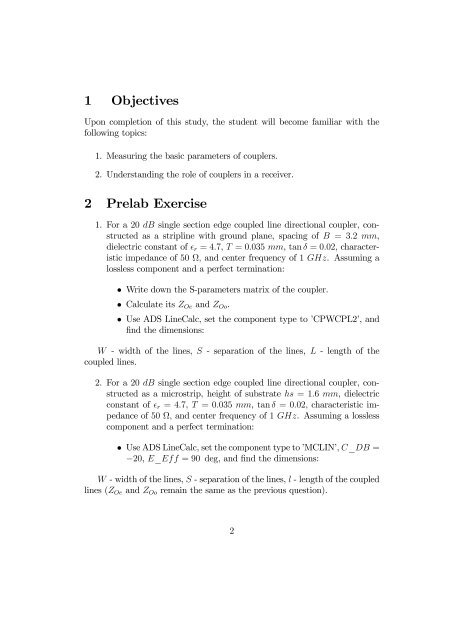
1 Objectives<br />
Upon completion of this study, the student will become familiar with the<br />
following topics:<br />
1. Measuring the basic parameters of couplers.<br />
2. Understanding the role of couplers in a receiver.<br />
2 Prelab Exercise<br />
1. For a 20 dB single section edge coupled line directional coupler, constructed<br />
as a stripline with ground plane, spacing of B =3.2 mm,<br />
dielectric constant of r =4.7, T =0.035 mm, tan δ =0.02, characteristic<br />
impedance of 50 Ω, and center frequency of 1 GHz. Assuming a<br />
lossless component and a perfect termination:<br />
• Write down the S-parameters matrix of the coupler.<br />
• Calculate its Z Oe and Z Oo .<br />
• UseADSLineCalc,setthecomponenttypeto’CPWCPL2’,and<br />
find the dimensions:<br />
W - width of the lines, S - separation of the lines, L -lengthofthe<br />
coupled lines.<br />
2. For a 20 dB single section edge coupled line directional coupler, constructed<br />
as a microstrip, height of substrate hs =1.6 mm, dielectric<br />
constant of r =4.7, T =0.035 mm, tan δ =0.02, characteristic impedance<br />
of 50 Ω, and center frequency of 1 GHz. Assuming a lossless<br />
component and a perfect termination:<br />
• UseADSLineCalc,setthecomponenttypeto’MCLIN’,C_DB =<br />
−20, E_Eff =90 deg,andfind the dimensions:<br />
W - width of the lines, S - separation of the lines, l - length of the coupled<br />
lines (Z Oe and Z Oo remain the same as the previous question).<br />
2


