Experiment 5 â Coupler Design.
Experiment 5 â Coupler Design.
Experiment 5 â Coupler Design.

You also want an ePaper? Increase the reach of your titles
YUMPU automatically turns print PDFs into web optimized ePapers that Google loves.
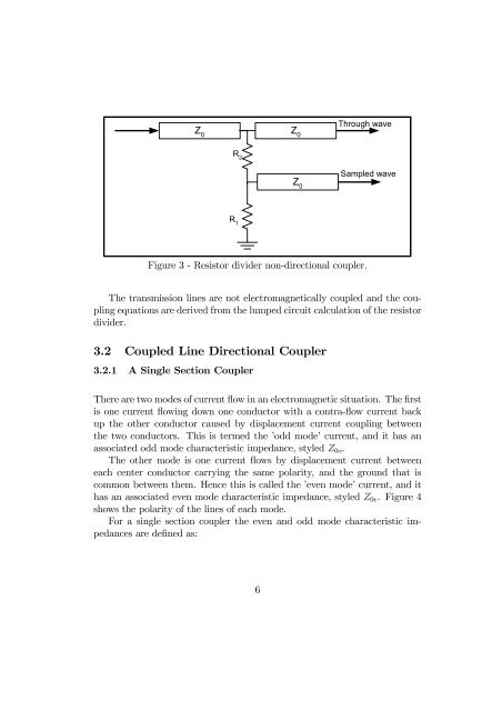
Z 0<br />
Z 0<br />
Through wave<br />
R 2<br />
Z 0<br />
Sampled wave<br />
R 1<br />
Figure 3 - Resistor divider non-directional coupler.<br />
The transmission lines are not electromagnetically coupled and the coupling<br />
equations are derived from the lumped circuit calculation of the resistor<br />
divider.<br />
3.2 Coupled Line Directional <strong>Coupler</strong><br />
3.2.1 A Single Section <strong>Coupler</strong><br />
There are two modes of current flow in an electromagnetic situation. The first<br />
is one current flowing down one conductor with a contra-flow current back<br />
up the other conductor caused by displacement current coupling between<br />
the two conductors. This is termed the ’odd mode’ current, and it has an<br />
associated odd mode characteristic impedance, styled Z 0o .<br />
Theothermodeisonecurrentflows by displacement current between<br />
each center conductor carrying the same polarity, and the ground that is<br />
common between them. Hence this is called the ’even mode’ current, and it<br />
has an associated even mode characteristic impedance, styled Z 0e .Figure4<br />
shows the polarity of the lines of each mode.<br />
For a single section coupler the even and odd mode characteristic impedances<br />
are defined as:<br />
6