REFERENCE GUIDE - Hitachi Kokusai Electric America, Ltd.
REFERENCE GUIDE - Hitachi Kokusai Electric America, Ltd.
REFERENCE GUIDE - Hitachi Kokusai Electric America, Ltd.

Create successful ePaper yourself
Turn your PDF publications into a flip-book with our unique Google optimized e-Paper software.
Lights up, when the DR2500-ASI is powered by the power supply.<br />
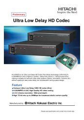
4.4 Connectors and indicators at the rear of the device<br />
ASI in<br />
Genlock L Audio R<br />
µPC/Data 12VDC AUX<br />
HD-SDI<br />
HD-SDI<br />
Figure 321: : Rear Rear of the of DR2500ASI the DR2500HD Diversity Receiver<br />
At the rear of the DR2500HD Diversity Receiver:<br />
• 1 X “ASI in”, this is the ASI signal which comes from the Fibre-IDU<br />
• 1 X “Genlock in” for Synchronization [SD- or HD-SDI], BNC female<br />
• 2 X “SDI out” for video, BNC female<br />
• 1 X "12-18V-DC" 4-pol XLR connector for 12-18V DC power supply<br />
• “Ant.1” and “Ant.2”are 2 X SMA (f) sockets for RF input<br />
• 1 X “uPC/Data” is a Serial 9 pin Sub-D (f) socket for remote control RX and data<br />
output<br />
• “Audio L” and “Audio R” are 3-pol XLR connector for audio out<br />
Caution<br />
Be sure that the ventilation openings are not obstructed.<br />
Reference Guide: HITACHI Wireless Camera (HITACHI OEM Version) Page 17<br />
March 2010