Airfoil Design and Optimization - IAG
Airfoil Design and Optimization - IAG
Airfoil Design and Optimization - IAG

Create successful ePaper yourself
Turn your PDF publications into a flip-book with our unique Google optimized e-Paper software.
Lutz, Th.<br />
<strong>Airfoil</strong> <strong>Design</strong> <strong>and</strong> <strong>Optimization</strong><br />
The aerodynamic efficiency of mildly swept wings is mainly influenced by the characteristics of the airfoil sections.<br />
The specific design of airfoils is therefore one of the classical tasks of aerodynamics. Since the airfoil characteristics<br />
are directly dependent on the inviscid pressure distribution the application of inverse calculation methods is obvious.<br />
The direct numerical airfoil optimization offers an alternative to the manual design <strong>and</strong> attracts increasing interest.<br />
1. Inverse Subsonic <strong>Airfoil</strong> <strong>Design</strong><br />
In order to find a proper airfoil shape for a specific aerodynamic application different approaches may be used. In<br />
former times, when no theoretical methods were available, relevant geometric parameters were varied systematically<br />
<strong>and</strong> the effect on the aerodynamic characteristics was measured in a series of wind-tunnel tests. The first extensive<br />
experimental investigations in this sense were performed at the AVA after completion of the Göttinger low-speed<br />
wind-tunnel in 1917/1918.<br />
After L. Pr<strong>and</strong>tl developed the boundary-layer theory it became obvious that the outer-flow velocity distribution<br />
along the airfoil surface determines the airfoil performance. This gave reason to develop inverse methods which<br />
enable the calculation of the airfoil contour from a given velocity distribution. First methods for the approximate<br />
inverse solution of the Laplace equation were developed in the late twenties <strong>and</strong> the thirties. Exact solutions based<br />
on a conformal mapping procedure were proposed by Mangler (1938) <strong>and</strong> Lighthill (1945).<br />
When inverse methods were available, knowledge was established how to shape the velocity distribution in order to<br />
obtain favourable airfoil characteristics, e. g. with respect to minimum drag or maximum lift. A milestone represent<br />
the well-known NACA laminar flow airfoils designed in the late thirties. As further examples the investigations of<br />
Eppler, Stratford <strong>and</strong> Wortmann should be mentioned.<br />
A significant progress in airfoil design was achieved in the fifties by coupling the potential-flow methods with integral<br />
boundary-layer procedures to consider viscous effects. Since then, a large number of subsonic airfoil design tools<br />
were developed, for example the Eppler/Somers code or the methods of Drela. In the h<strong>and</strong>s of experienced users<br />
such methods enable a carefully directed design <strong>and</strong> the adaption of the airfoil characteristics to specific applications.<br />
A good example in this respect is documented in the progress achieved in the aerodynamic performance of modern<br />
sailplanes. A significant portion of the improvements can be attributed to the sucessful design of low-drag laminar<br />
flow airfoils (e. g. DU, E, FX or HQ airfoils).<br />
Another significant amount of investigations on inverse methods for the regime of transonic flows were performed in<br />
the seventies after the discovery of the supercritical airfoils. Due to the availability of supercomputers it is nowadays<br />
possible to h<strong>and</strong>le semi-inverse solutions of the Euler equation, the coupled Euler boundary-layer equations or even<br />
for the Reynolds-averaged Navier-Stokes (RANS) equations.<br />
2. Direct Numerical <strong>Airfoil</strong> <strong>Optimization</strong><br />
An alternative to the inverse or semi-inverse procedure is offered by direct numerical optimization. With this<br />
approach an automated search for an optimal solution with respect to a user-specified objective function, e. g.<br />
minimzation of drag, is performed. This is done by means of an iterative variation of the chosen design variables.<br />
To parameterize the airfoil contour mostly geometric shape functions are applied with the respective coefficients<br />
representing the design variables. The choice of a proper optimization algorithm strongly depends on the topology<br />
of the considered objective function, the airfoil parameterization, the number of design variables <strong>and</strong> finally on the<br />
efficiency of the aerodynamic model. In general, gradient methods converge fast for simple topologies of the objective<br />
function but one may be trapped in a local optimum if a multimodal objective function is considered. Stochastic<br />
algorithms offer a greater chance to avoid this problem <strong>and</strong> can also cope with complex topologies but usually require<br />
much more iterations. The combination of stochastic optimizers with costly high-accuracy flow-solvers, e. g. based<br />
on the solution of the RANS equations, is therefore still limited to a relatively small number of design variables.
Numerical optimizations of subsonic airfoils featuring a detailed representation of the complete contour are hardly<br />
known. To reduce the computational effort, potential-flow methods coupled with integral boundary-layer procedures<br />
are preferred for the aerodynamic analysis, the number of optimization cycles is limited <strong>and</strong> a moderate number of<br />
design variables (usually below 10 ∼ 15) is considered. Actually, most of the numerically optimized subsonic airfoils<br />
published so far show a great similarity to the initial shape.<br />
3. Example on Numerical Shape <strong>Optimization</strong> of Subsonic NLF <strong>Airfoil</strong>s<br />
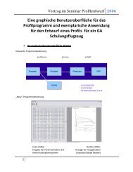
The objective of numerical optimizations performed by the present author<br />
was to design natural laminar flow (NLF) airfoils which show minimized<br />
average drag for a user-specified design lift region [1], [2]. In order<br />
to enable a detailed airfoil representation a large number of 34 design<br />
variables was considered. Contrary to the usual approach the airfoil was<br />
not parameterized by geometric shape functions. Instead, an inverse<br />
conformal mapping procedure according to Eppler was applied to generate<br />
the airfoil contour. The input parameters of this method directly<br />
control the local outer-flow velocity gradient <strong>and</strong> finally the boundarylayer<br />
development. A spline representation of the critical leading-edge<br />
region is avoided with this approach.<br />
The potential-flow method was coupled with an integral boundary-layer<br />
procedure utilizing closure relations according to Eppler for laminar flow.<br />
The method proposed by Drela with a new shape-factor relation is used<br />
to calculate turbulent boundary-layers. To predict the laminar to turbulent<br />
transition location, an e n database method based on spatial stability<br />
analysis for Falkner-Skan self-similar profiles was implemented. The effect<br />
of ’short’ transitional separation bubbles is considered by means of a<br />
new efficient bubble model. The complete aerodynamic model was coupled<br />
with a commercial hybrid optimizer which consists of a combination<br />
of genetic algorithm, downhill simplex <strong>and</strong> a gradient method.<br />
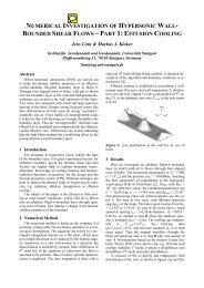
Figure 1: Inviscid velocity distribution<br />
for the optimized airfoil<br />
One optimization result is depicted in Figs. 1<br />
<strong>and</strong> 2. The objective was to minimize the<br />
average drag coefficient for angles of attack<br />
α design =[2 ◦ , 3 ◦ , ..., 8 ◦ ] relative to the<br />
zero-lift line. Two Reynolds numbers were<br />
considered, namely Re design =3· 10 6 <strong>and</strong><br />
9 · 10 6 . In order to prevent a breakdown<br />
in lift at off-design conditions <strong>and</strong> to enhance<br />
the stall characteristics, the curvature<br />
of the lift curve was limited for α =<br />
[2 ◦ , 3 ◦ , ..., 15 ◦ ]. The resulting airfoil shows<br />
features which are well-known from manual<br />
airfoil design such as smooth transition<br />
ramps or a Stratford-like turbulent pressure<br />
recovery on the lower side (see Fig. 1).<br />
1.5<br />
Present method, n<br />
c crit.<br />
= 11.13<br />
l<br />
Eppler code<br />
Experiment <strong>IAG</strong><br />
1.0<br />
Re=3x10 6<br />
0.5<br />
0.0<br />
0.000 0.005 0.010<br />
c d<br />
0.0 0.5 x tra /c<br />
1.0<br />
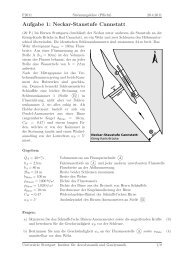
Figure 2: Predicted <strong>and</strong> measured drag polar for the optimized airfoil<br />
Wind-tunnel tests for the optimized airfoil showed very low drag coefficients inside the laminar bucket which exactly<br />
coincides with the design lift region, see Fig. 2. The optimization method has furthermore been applied to design of<br />
airfoils which show minimized trailing-edge noise or minimal derivation to a user-specified drag polar.<br />
4. References<br />
1 Lutz, Th.: Berechnung und Optimierung subsonisch umströmter Profile und Rotationskörper. VDI Fortschritt–Berichte,<br />
Reihe 7: Strömungstechnik, Nr. 378, ISBN 3-18-337807-8.<br />
2 Lutz, Th. <strong>and</strong> Wagner, S.: Numerical Shape <strong>Optimization</strong> of Subsonic <strong>Airfoil</strong> Sections. Proc. ECCOMAS 2000: European<br />
Congress on Computational Methods in Applied Sciences <strong>and</strong> Engineering, Barcelona, September 11–14, 2000.<br />
Addresses: Thorsten Lutz, Institute for Aerodynamics <strong>and</strong> Gas Dynamics, University of Stuttgart (<strong>IAG</strong>),<br />
Pfaffenwaldring 21, D-70550 Stuttgart, email: lutz@iag.uni-stuttgart.de