

Pfeiffer, TC 400, Electronic Drive Unit, Operating_Instructions
Pfeiffer, TC 400, Electronic Drive Unit, Operating_Instructions
Pfeiffer, TC 400, Electronic Drive Unit, Operating_Instructions

Create successful ePaper yourself
Turn your PDF publications into a flip-book with our unique Google optimized e-Paper software.
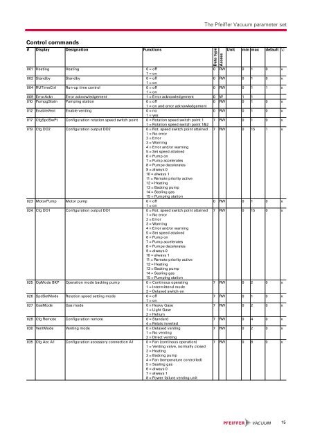
The <strong>Pfeiffer</strong> Vacuum parameter set<br />
Control commands<br />
# Display Designation Functions<br />
Data type<br />
Access<br />
<strong>Unit</strong> min max default <br />
001 Heating Heating 0 = off<br />
0 RW 0 1 0 x<br />
1 = on<br />
002 Standby Standby 0 = off<br />
0 RW 0 1 0 x<br />
1 = on<br />
004 RUTimeCtrl Run-up time control 0 = off<br />
0 RW 0 1 1 x<br />
1 = on<br />
009 ErrorAckn Error acknowledgement 1 = Error acknowledgement 0 W 1 1<br />
010 PumpgStatn Pumping station 0 = off<br />
0 RW 0 1 0 x<br />
1 = on and error acknowledgement<br />
012 EnableVent Enable venting 0 = no<br />
0 RW 0 1 0 x<br />
1 = yes<br />
017 CfgSpdSwPt Configuration rotation speed switch point 0 = Rotation speed switch point 1 7 RW 0 1 0 x<br />
1 = Rotation speed switch point 1&2<br />
019 Cfg DO2 Configuration output DO2 0 = Rot. speed switch point attained 7 RW 0 15 1 x<br />
1 = No error<br />
2 = Error<br />
3 = Warning<br />
4 = Error and/or warning<br />
5 = Set speed attained<br />
6 = Pump on<br />
7 = Pump accelerates<br />
8 = Pumpe decelerates<br />
9 = always 0<br />
10 = always 1<br />
11 = Remote priority active<br />
12 = Heating<br />
13 = Backing pump<br />
14 = Sealing gas<br />
15 = Pumping station<br />
023 MotorPump Motor pump 0 = off<br />
0 RW 0 1 0 x<br />
1 = on<br />
024 Cfg DO1 Configuration output DO1 0 = Rot. speed switch point attained 7 RW 0 15 0 x<br />
1 = No error<br />
2 = Error<br />
3 = Warning<br />
4 = Error and/or warning<br />
5 = Set speed attained<br />
6 = Pump on<br />
7 = Pump accelerates<br />
8 = Pumpe decelerates<br />
9 = always 0<br />
10 = always 1<br />
11 = Remote priority active<br />
12 = Heating<br />
13 = Backing pump<br />
14 = Sealing gas<br />
15 = Pumping station<br />
025 OpMode BKP Operation mode backing pump 0 = Continous operating<br />
7 RW 0 2 0 x<br />
1 = Intermittend mode<br />
2 = Delayed switch-on<br />
026 SpdSetMode Rotation speed setting mode 0 = off<br />
7 RW 0 1 0 x<br />
1 = on<br />
027 GasMode Gas mode 0 = Heavy Gase<br />
7 RW 0 2 0 x<br />
1 = Light Gase<br />
2 = Helium<br />
028 Cfg Remote Configuration remote 0 = Standard<br />
7 RW 0 4 0 x<br />
4 = Relais inverted<br />
030 VentMode Venting mode 0 = Delayed venting<br />
7 RW 0 2 0 x<br />
1 = No venting<br />
2 = Direct venting<br />
035 Cfg Acc A1 Configuration accessory connection A1 0 = Fan (continous operation)<br />
1 = Venting valve, normally closed<br />
2 = Heating<br />
3 = Backing pump<br />
4 = Fan (temperature controlled)<br />
5 = Sealing gas<br />
6 = always 0<br />
7 = always 1<br />
8 = Power failure venting unit<br />
7 RW 0 8 0 x<br />
15


