EAGLE Version 6 Update Information - Cadsoft
EAGLE Version 6 Update Information - Cadsoft
EAGLE Version 6 Update Information - Cadsoft

Create successful ePaper yourself
Turn your PDF publications into a flip-book with our unique Google optimized e-Paper software.
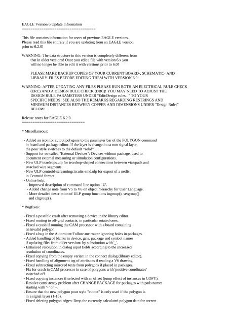
<strong>EAGLE</strong> <strong>Version</strong> 6 <strong>Update</strong> <strong>Information</strong><br />
==================================<br />
This file contains information for users of previous <strong>EAGLE</strong> versions.<br />
Please read this file entirely if you are updating from an <strong>EAGLE</strong> version<br />
prior to 6.2.0!<br />
WARNING: The data structure in this version is completely different from<br />
that in older versions! Once you edit a file with version 6.x you<br />
will no longer be able to edit it with versions prior to 6.0!<br />
PLEASE MAKE BACKUP COPIES OF YOUR CURRENT BOARD-, SCHEMATIC- AND<br />
LIBRARY-FILES BEFORE EDITING THEM WITH VERSION 6.0!<br />
WARNING: AFTER UPDATING ANY FILES PLEASE RUN BOTH AN ELECTRICAL RULE CHECK<br />
(ERC) AND A DESIGN RULE CHECK (DRC)! YOU MAY NEED TO ADJUST THE<br />
DESIGN RULE PARAMETERS UNDER "Edit/Design rules..." TO YOUR<br />
SPECIFIC NEEDS! SEE ALSO THE REMARKS REGARDING RESTRINGS AND<br />
MINIMUM DISTANCES BETWEEN COPPER AND DIMENSIONS UNDER "Design Rules"<br />
BELOW!<br />
Release notes for <strong>EAGLE</strong> 6.2.0<br />
=============================<br />
* Miscellaneous:<br />
- Added an icon for cutout polygons to the parameter bar of the POLYGON command<br />
in board and package editor. If the layer is changed to a non signal layer,<br />
the pour style switches to the default "solid".<br />
- Support for so-called "External Devices": Devices without package, used to<br />
document external measuring or simulation configurations.<br />
- New ULP teardrops.ulp for teardrop-shaped connections between vias/pads and<br />
attached wire segments.<br />
- New ULP centroid-screamingcircuits-smd.ulp for export of a netlist<br />
in Centroid format.<br />
- Online help:<br />
- Improved description of command line option '-U'.<br />
- Added change note from V5 to V6 on object hierarchy for User Language.<br />
- More detailed description of ULP group functions ingroup(), setgroup()<br />
and clrgroup().<br />
* Bugfixes:<br />
- Fixed a possible crash after removing a device in the library editor.<br />
- Fixed routing to off-grid contacts, in particular rotated ones.<br />
- Fixed a crash if running the CAM processor with a board containing<br />
an invalid polygon.<br />
- Fixed a bug in the Autorouter/Follow-me router ignoring holes in packages.<br />
- Added handling of blanks in device, gate, package and symbol names<br />
if updating files from older versions by substitution with '_'.<br />
- Enhanced resolution in dialog input fields according to the increased<br />
resolution of coordinates.<br />
- Fixed copying from the empty variant in the connect dialog (library editor).<br />
- Fixed handling of alignment tag of attributes if reading a V6 drawing<br />
- Fixed subtracting mirrored texts from polygons if placed in packages.<br />
- Fix for crash in CAM processor in case of polygons with 'positive coordinates'<br />
switched off.<br />
- Fixed copying instances if selected with an offset (jump effect of instances in COPY).<br />
- Resolve consistency problem after CHANGE PACKAGE for packages with pads names<br />
starting with '+' or '-'.<br />
- Ensure that the new polygon pour style "cutout" is only used if the polygon is<br />
in a signal layer (1-16).<br />
- Fixed deleting polygon edges: Drop the currently calculated polygon data for correct
update after delete.<br />
- Copy-Paste: Adapt net class of pasted net if net with same name already exists.<br />
- ULP: Fix syntax problem for instances() loop of UL_SHEET.<br />
- Fixed renaming of signal polygons: The polygon sometimes vanishes if already calculated.<br />
- Fixed UNDO/REDO renaming of calculated signal polygons: Drop the obsolete calculation.<br />
- Fixed a crash if mirroring instances during MOVE command if a pin is directly connected<br />
to another.<br />
- Fixed possible corruptness of symbol names after drag&drop of devices from<br />
control panel into the library editor.<br />
- Fixed the DRC calculation of 'Stop Mask' errors of long/offset pads.<br />
- Fixed position of dimensions if generating a CAM processor output<br />
with option 'positive coordinates' on.<br />
- Fixed a crash in library editor if running a script with many changes<br />
between edit modes (device, package, symbol).<br />
- Fixed autorouting boards with packages containing polygons as pad shapes.<br />
- Resolve consistency problem after REPLACE in special cases.<br />
- Fix for REPLACE of devices that don't match in their gates positions<br />
or names (wrong matching leading to library update failure).<br />
- Fix for missing devices in the ADD dialog if they are without technologies.<br />
- Fixed a performance issue if loading a board coming from an older version<br />
with many rotated elements with contacts connected to large signals.<br />
- Fixed open file problem due to erroneous handling of UTF8 characters.<br />
- Added handling of blanks in pin, pad and smd names<br />
if updating files from older versions by substitution with '_'.<br />
- Added handling of empty gate names if loading files from older versions<br />
by substitution with 'G$$1' (exotic to minimize ambiguities).<br />
- ULP: Set the proper sheet context if looping through pinrefs of a net.<br />
- ULP: Fixed looping through variants of an element in a ULP.<br />
- ULP: Provide the proper device context to access pinref.pin.contact.<br />
- Improved syntax of the VARIANT command to allow variant names beginning<br />
with '+' or '-'.<br />
- Fixed displaying the library description in the ADD dialog for libraries with<br />
a symbol description.<br />
- Fixed the CONNECT command if gate names starting with '.' are used.<br />
- Fix handling umlauts or 'ß' in library names when loading files from older<br />
versions.<br />
- Fixed library update problem related to several parts using same deviceset<br />
but different gate combinations.<br />
- Fixed clearing content of the parameter toolbar while processing a command<br />
sequence.<br />
- Fixed handling multiple pads connected to the same pin by adding an<br />
additional attribute 'routetag' to the XML data format.<br />
- Fixed changing the value of attributes of instances.<br />
- Fixed updating of drawings coming from older versions containing smashed<br />
Elements/Instances with multiple identical placeholder texts like NAME or VALUE.<br />
- Fixed changing assembly variants: update the drawing accordingly.<br />
- Fixed UNDO/REDO of assembly variant changes.<br />
- Fixed layer visibility of not populated elements in current assembly variant.<br />
- Fixed handling assembly variants in ULPs: provide the cross drawn over<br />
not populated parts in the schematic as wires of the according instance symbols.<br />
Skip the objects in layers like tPlace/bPlace if looping through the objects<br />
of not populated elements in the board.<br />
- Proper support for case insensitive handling of assembly variant names in the<br />
VARIANT dialog.<br />
- Fix for inconsistency problem after PINSWAP and UNDO.<br />
- Fixed handling assembly variants in the CAM processor: Draw a cross over not<br />
populated parts in the schematic and do not draw the objects of not populated<br />
elements in layers like tPlace/bPlace.<br />
- Enhanced the CAM processor GUI to allow selecting a specific assembly variant<br />
and to display the currently selected assembly variant in the status bar.<br />
- Fixed sorting 'numeric string' arrays in the user language for strings<br />
containing a numeric sequence greater than 2147483647.<br />
- Fixed drawing the cross of not populated and smashed parts in the schematic
after moving one of its texts: the size of the cross does no longer take<br />
the texts of smashed parts into account.<br />
- Fixed exporting the pad names on pins if generating CAM processor output.<br />
- Added missing ULP constants (ALIGN_...).<br />
- Restored the possibility to provoke the connectivity of nets on pins by<br />
pseudo movements of instances (selecting and releasing at the same location).<br />
- Fix for consistency problem after library update (REPLACE or explicit UPDATE)<br />
due to improper update of changed symbols.<br />
- Fixed wrong orientation of texts after UNDO of a PASTE command.<br />
- Fixed SMASH of instances/elements with placeholder texts with an align<br />
other than the default align bottom-left.<br />
- Fixed a net class inconsistency if a supply net with a net class other than 0<br />
already exists and is continued on another sheet by adding supply devices<br />
pin to pin.<br />
- Set net class of newly created supply nets by placing supply devices pin to pin<br />
to the current net class.<br />
- Fixed a crash when copying special ('grubby') polygons.<br />
- Fixed the CLASS command to handle clearances to classes greater than 9.<br />
- Fixed drawing of dimensions while modifying them (avoiding artefacts).<br />
- Added a missing window refresh after changing of dimension settings.<br />
- Fixed renaming nets for the case 'every Segment on this Sheet'.<br />
- ULP functions netget/netpost: Workaround for wrong SSL error "Handshake failed"<br />
for SSL connections due to erroneous OpenSSL lib on Windows XP SP3.<br />
If the error occurs the user can decide wether to continue anyway.<br />
This also fixes connection problems with DesignLink.<br />
- Fix for proper group selection by ULP function setgroup.<br />
- GROUP selection with ctrl-click: Fix for clicks getting lost,<br />
fix for handling of polygons.<br />
- Fixed reading the description of the Design Rules.<br />
- Fixed automatic generation of element names in project context: The names of<br />
parts without package (e.g. supply devices or frames) were not taken into account.<br />
- Fix for possible loss of changes in board editor after loading another project<br />
pair from unchanged schematic editor and vice versa.<br />
- Fix for "empty screen effect" due to degenerated arcs from older <strong>EAGLE</strong> versions.<br />
- Extend too tight radius limitation for circles.<br />
- Fixed crash in SHOW after selection of one entity and deselection with Ctrl-click.<br />
- Fixed drawing of very large rectangles.<br />
- Fixed a crash in ULP function setgroup() if executed from library editor and<br />
nothing edited.<br />
Release notes for <strong>EAGLE</strong> 6.1.0<br />
=============================<br />
* DIMENSION command:<br />
- Added a note about the settings for dimension objects to the online help of<br />
the DIMENSION command.<br />
* Miscellaneous:<br />
- The new option "Legacy mouse wheel mode" in "Options/User interface" can be<br />
activated under Mac OS X to switch back to the mouse wheel handling as it<br />
was in version 5.<br />
- Online help for SCRIPT command: Add a section about script labels.<br />
* Bugfixes:<br />
- Fixed a missing screen update after updating a symbol in a schematic<br />
drawing, where the new version of the symbol extends outside the<br />
surrounding rectangle of the entire drawing.<br />
- Fix for tweaking off polygon orphans in CAM processor output with<br />
positive coordinates.
- Correct support for new members "headline" and "description" of ULP types<br />
UL_BOARD, UL_SCHEMATIC and UL_SHEET.<br />
- Fixed subtracting texts with vector font from polygons if placed in packages.<br />
- Fixed changing the font of texts if the drawing has set 'Always Vector Font'.<br />
- Fixed handling attributes with empty names in elements when updating a<br />
board from before version 6.0 (they will be silently ignored).<br />
- Fixed subtracting texts with vector font from polygons in CAM processor output.<br />
- Fixed erroneously checking polygons with rank 6 and polygons with a smaller rank<br />
in the DRC.<br />
- Fixed jumping initial airwire position when routing in special cases.<br />
- Fixed a crash in the ROUTE command when routing a track that provokes<br />
an immediate optimize.<br />
- Fixed a crash in the Control Panel's tree view when renaming an item, and<br />
the new name already exists.<br />
- ADD command: Ensure proper initialization of part values if the device has the attribute<br />
'VALUE' set or the eaglerc switch Sch.Cmd.Add.AlwaysUseDeviceNameAsValue is set.<br />
- Fixed a crash in the RIPUP command if used in a non-board drawing.<br />
- Fixed automatic generation of part names in project context: The names of elements<br />
without a corresponding part were not taken into account.<br />
- Paste from file: If nets/signals from paste buffer are connected to an existing<br />
net/signal, update netclasses of paste buffer nets/signals accordingly.<br />
Warn the user before in case of changes.<br />
- Fixed a crash if deleting a group containing a net wire and a junction<br />
in special constellation.<br />
- Smashed Elements/Instances: Ensure load of drawing in case of multiple identical<br />
placeholder texts like NAME or VALUE.<br />
- Fixed drawing of polygons of mirrored elements with the CAM Processor<br />
(use mirrored layer if applicable).<br />
- Fixed a possible crash if opening a library panel tree containing<br />
a library that would imply an update report.<br />
Release notes for <strong>EAGLE</strong> 6.0.0<br />
=============================<br />
* Platforms:<br />
- The Mac OS X version of <strong>EAGLE</strong> now requires an Intel Mac. It no longer runs<br />
on PPC machines.<br />
- Mac OS X 10.4, Mac OS X 10.5 and Windows 2000 are no longer officially<br />
supported.<br />
- If you are running Mac OS X 10.7 "Lion" and are using a track pad, you<br />
can now use the "two-finger-pan" gestures for panning the content of the<br />
editor window. Zooming in and out is done with the "pinch" gesture.<br />
- To avoid problems with overwriting an existing installation of <strong>EAGLE</strong> with<br />
a newer version on Mac OS X, the default installation directory now contains<br />
the current version number (same as on Windows and Linux).<br />
- The Mac OS X installer now allows reverting back to older versions of <strong>EAGLE</strong>.<br />
* File data format changed to XML:<br />
- The <strong>EAGLE</strong> file format has been changed from binary to XML.<br />
- The complete definition of the new <strong>EAGLE</strong> file format can be found in the<br />
file "doc/eagle.dtd".<br />
- Existing files will be automatically updated to the new format when<br />
they are saved with version 6.<br />
- The pin direction "I/O" has been changed to "io" (without the slash).<br />
Wherever a pin direction is allowed in command line input, the old value<br />
will still be accepted for compatibility with earlier versions, but in the<br />
XML files only "io" will be used.<br />
* Mulitple pads connected to the same pin:
- Multiple pads can now be connected to the same pin.<br />
- If a pin is connected to multiple pads, and the pad name is visible on<br />
the pin, the smallest of all pad names connected to that pin is displayed,<br />
followed by an asterisk ('*') to indicate that there is more than one pad.<br />
After the asterisk the total number of pads connected to this pin is<br />
displayed.<br />
- The "Same signals" check between SMDs and pads/SMDs is no longer applied<br />
within the same package.<br />
* Arbitrary pad shapes:<br />
- Any wires and polygons in signal layers (1-16) drawn in a package<br />
that are connected to a pad or smd are now considered electrically<br />
connected to that pad/smd. This allows the definition of arbitrary<br />
pad shapes.<br />
See "Help/Editor Commands/PAD|SMD/Arbitrary Pad Shapes".<br />
- The 'rank' parameter is now obsolete for polygons in packages.<br />
Package polygons in signal layers that are not connected to a pad/smd will<br />
be handled as if they had a rank of 0.<br />
* Cutout polygons:<br />
- The new polygon pour style "cutout" can be used to define polygons that<br />
get "subtracted" from all other signal polygons within the same layer.<br />
See "Help/Editor Commands/POLYGON/Polygon cutouts".<br />
* Dimensions:<br />
- The new command DIMENSION can be used to draw dimensions.<br />
See "Help/Editor Commands/DIMENSION".<br />
* Differential pair routing:<br />
- The ROUTE command now supports routing of "Differential Pair" signals.<br />
- The RATSNEST command prefers open wire ends when generating airwires<br />
for Differential Pair signals.<br />
* Automatic meanders:<br />
- The new command MEANDER can be used to balance the lengths of<br />
differential pair signals, or to increase the length of a signal segment<br />
to a given target length.<br />
* Assembly variants:<br />
- The new command VARIANT can be used to define assembly variants.<br />
Assembly variants define whether a given part is actually populated<br />
on the board, and what value and technology it has (if different from<br />
the default).<br />
- You can access assembly variants by opening the dialog under<br />
"Edit/Assembly variants...".<br />
- If a drawing contains assembly variants, the action toolbar shows a new<br />
combo box that allows you to select one of these variants.<br />
- The VALUE command always changes the value of a part in the currently<br />
selected assembly variant.<br />
- The new User Language objects UL_VARIANTDEFS and UL_VARIANTS, as well as<br />
the new members UL_SCHEMATIC.variantdefs, UL_BOARD.variantdefs,<br />
UL_PART.variants and UL_ELEMENT.variants can be used to access assembly<br />
variants from a User Language Program.<br />
- The new User Language functions setvariant() and variant() can be used<br />
to set and query the current assembly variant.<br />
- The new User Language members UL_PART.populate and UL_ELEMENT.populate<br />
can be used to determine whether a part has to be populated in the
current assembly variant.<br />
- The new placeholder >ASSEMBLY_VARIANT can be used to display the name of<br />
the current assembly variant. ASSEMBLY_VARIANT can therefore no longer be<br />
used as an attribute name.<br />
- The new command line option -A can be used to specify a particular<br />
assembly variant when running the CAM Processor.<br />
- The commands ADD, CHANGE PACKAGE | TECHNOLOGY, REPLACE, UPDATE and VALUE<br />
can only be used if no assembly variant is active.<br />
* Text alignment:<br />
- Texts can now have one of nine different alignments, consisting of<br />
combinations of left, right, center, top and bottom.<br />
- The reading direction of vertical texts can now be selected from "up"<br />
and "down" in "Options/User interface".<br />
* Increased internal resolution:<br />
- The internal resolution of <strong>EAGLE</strong> has been increased by a factor of 32.<br />
It used to be 0.1 micron and is now 0.003125 micron. This allows drawings<br />
in imperial units to use exact values for multiples of 1/4, 1/8, 1/16,<br />
1/32 and 1/64 mil.<br />
- The maximum drawing area is now 4x4 meters (about 150x150 inch).<br />
- If a User Language Program directly handles coordinates or sizes in<br />
editor units and needs to know the actual value of one editor unit, it<br />
needs to be adjusted to use the new value.<br />
- The new User Language functions inch2u(), mic2u(), mil2u() and mm2u()<br />
can be used to convert the respective units to internal editor units.<br />
- Due to the increased resolution of coordinates, any approved ERC or DRC<br />
errors from older versions can no longer be recognized as such. Therefore,<br />
when you run the ERC/DRC after updating a file to version 6, these errors<br />
will show up again and you may have to approve them again<br />
- Once you overwrite a project file (eagle.epf) from an older version with<br />
this new version of <strong>EAGLE</strong>, the dimension values in it will be stored in<br />
a different format. If you then load such a file with an old version of<br />
<strong>EAGLE</strong>, all menu entries (like wire widths or drill diameters) will fall<br />
back to their default values.<br />
* Supply layers:<br />
- Supply layers (i.e. layers with names that start with a '$') are no longer<br />
treated special. Layers for supply signals now need to be realized using<br />
signal polygons.<br />
- When a board drawing from an older version of <strong>EAGLE</strong> is loaded, any supply<br />
layers it contains will be renamed by moving the '$' to the end of the<br />
name. This makes sure automated scripts that treat a supply layer as<br />
"negative" don't make a mistake, while still indicating that layer as<br />
having been a supply layer. The functionality of the supply layer is<br />
replaced by a signal polygon with the proper name, using the minimum wire<br />
width from the net class of that signal. The polygon is drawn into the<br />
former supply layer as a rectangular shape, covering the area defined by<br />
any wires in the Dimension layer, by pads or by vias. The Autorouter setup<br />
is modified in such a way that the layer containing the generated polygon<br />
is activated (with preferred direction '*'), and the costs for that layer<br />
set to 99 in all passes.<br />
VERY IMPORTANT:<br />
After updating a board with supply layers from an older version, make<br />
sure you run the RATSNEST command to verify whether all pads are still<br />
connected to the respective signal.<br />
* BGA escape routing:
- Route all signals are out of a BGA following design rules and available layers.<br />
ULP solution. Start with 'run route-bga element'.<br />
* Userdefined context menus:<br />
- With the SET command userdefined entries can be made into the context menus of<br />
selectable Eagle object types. They are stored in the eaglerc file.<br />
* User Language:<br />
- The User Language constants PAD_SHAPE_ANNULUS, PAD_SHAPE_THERMAL,<br />
VIA_SHAPE_ANNULUS and VIA_SHAPE_THERMAL are now obsolete.<br />
They are still tolerated for compatibility with old ULPs, but no pad or via<br />
will ever have such a shape.<br />
- The User Language member function UL_SHEET.parts is deprecated and should<br />
no longer be used. Use the new function UL_SHEET.instances instead.<br />
The old function is still available for compatibility with ULPs written<br />
for older versions.<br />
- The User Language objects UL_BOARD, UL_SCHEMATIC, UL_SHEET and UL_SYMBOL<br />
new have the new data members 'description' and 'headline'.<br />
- The User Language data member UL_PIN.contact is deprecated, because a pin<br />
can now be connected to multiple pads. It will work for backwards<br />
compatibility and as long as only one pad has been connected to the pin,<br />
but will cause a runtime error when used with a pin that is connected to<br />
more than one pad. Use the new loop member UL_PIN.contacts() instead.<br />
- The new User Language data members UL_PIN.route and UL_CONTACTREF.route<br />
tell whether all or any of the respective contacts need to be routed.<br />
- The new User Language object UL_DIMENSION can be used to access dimension<br />
objects.<br />
- The new User Language functions inch2u(), mic2u(), mil2u() and mm2u()<br />
can be used to convert the respective units to internal editor units.<br />
- The User Language object UL_TEXT now has the new data member 'align'.<br />
- The netpost() function has a new optional parameter to set the content<br />
type of the posted data.<br />
- PCB service (menu button and pcb-service.ulp): Extension to EuroCircuits<br />
for European, Pentalogix for American customers, depending on<br />
country settings.<br />
* CAM Processor:<br />
- The command line options '-a' and '-t' are no longer supported, because<br />
the CAM Processor doesn't use Annulus or Thermal symbols any more.<br />
For compatibility with existing scripts, these options are still<br />
tolerated, but they have no effect.<br />
- The aperture shapes "annulus" and "thermal" are no longer used by the<br />
CAM Processor.<br />
- Any parameters referring to "Annulus" or "Thermal" have been removed<br />
from the eagle.def file. They are still tolerated when using such a file<br />
from an older version of <strong>EAGLE</strong>, but they have no effect.<br />
* Design Rules:<br />
- Most of the parameters related to Thermal and Annulus have been removed<br />
from the "Supply" tab of the Design Rules dialog.<br />
- Changes to the Design Rules are now fully handled by UNDO/REDO.<br />
* AUTO command:<br />
- The AUTO command no longer clears the UNDO buffer (unless an existing job<br />
is continued/finished).<br />
* BOARD command:
- The BOARD command no longer clears the UNDO buffer of the schematic if a<br />
board is newly generated.<br />
* CHANGE command:<br />
- The CHANGE command now checks whether the selected object already has the<br />
requested property value, and changes it only if not. This may result in an<br />
actual CHANGE command not generating an UNDO step, because nothing has<br />
changed at all.<br />
- The new option CHANGE DTYPE can be used to change the type of<br />
dimension objects.<br />
- The new option CHANGE ALIGN can be used to change the alignment of<br />
text objects.<br />
* CLASS command:<br />
- The maximum number of net classes has been increased to 16.<br />
- Any changes made to the net classes with the CLASS command are now fully<br />
handled by UNDO/REDO.<br />
- The CLASS command now accepts class names that start with digits, as long<br />
as they are not a plain integer number.<br />
* CONNECT command:<br />
- The CONNECT command can now handle several pad names at once, to create<br />
a connection of several pads to one pin.<br />
- The new keywords ALL and ANY in the CONNECT command control whether all<br />
or any of the pads in a multiple pad connection need to be routed in the<br />
board.<br />
- Added a note to the online help of the CONNECT command, saying that this<br />
command works a lot faster if all connections of one device are given in<br />
one single call.<br />
* COPY command:<br />
- In older versions of <strong>EAGLE</strong> the COPY command was used solely to copy objects<br />
within a drawing, as opposed to the Windows behavior, where COPY places a<br />
copy of the selected objects (i.e. the GROUP) into the system's clipboard.<br />
As of version 6, <strong>EAGLE</strong>'s COPY command primarily behaves the same way as in<br />
other Windows applications, by putting a copy of the current group into the<br />
clipboard. The original functionality of copying selected objects, or<br />
copying library objects between libraries, is still fully available, which<br />
is especially important to keep existing scripts and ULPs working.<br />
What has also often irritated Windows users is that in <strong>EAGLE</strong> the CUT<br />
command has only copied the current group to the clipboard, but did not<br />
actually delete the group from the drawing. Since a CUT command that<br />
deletes the group would not be of much use in a board/schematic pair that<br />
is connected via forward-&backannotation, the CUT command has been<br />
removed from the main pulldown menu and the command button toolbar. It is<br />
still fully available from the command line or within scripts. The command<br />
SET Cmd.Copy.ClassicEagleMode 1<br />
restores the old behavior of both the COPY and the CUT command. Note that<br />
this setting only takes effect the next time you open an editor window.<br />
- Added a note to the online help of COPY about how to copy objects from<br />
one schematic sheet to an other.<br />
* DESCRIPTION command:<br />
- The DESCRIPTION command now also works in schematics, sheets, boards and<br />
symbols.
- If the first parameter to the DESCRIPTION command is an asterisk ('*'),<br />
the description of the library or schematic will be modified, as opposed to<br />
an individual device set, package, symbol or sheet.<br />
* DISPLAY command:<br />
- The DISPLAY command can now also delete internal layers, as long as they<br />
are empty.<br />
* DRC command:<br />
- If the DRC command is given an asterisk character ('*') as the first<br />
parameter, the Design Rules dialog will be opened and allow editing the<br />
Design Rules, without triggering an actual check when the dialog is<br />
confirmed.<br />
- The "Same signals" check between SMDs and pads/SMDs is no longer applied<br />
within the same package.<br />
* EDIT command:<br />
- Creating or reordering schematic sheets no longer clears the UNDO buffer.<br />
* ERC command:<br />
- If the ERC establishes consistency between a board and a schematic, it now<br />
stores this fact in the UNDO buffer. When going back in the UNDO history<br />
to a point before consistency was established, the forward-/backannotation<br />
will be disabled again. Note that doing REDO will not automatically<br />
re-establish consistency!<br />
Storing the fact that consistency has been established also truncates the<br />
UNDO buffer at that point.<br />
* ERRORS command:<br />
- The ERRORS dialog can now approve/disapprove all errors/warnings at once.<br />
You need to select and expand the desired section and press the<br />
"Approve all" or "Disapprove all" button, respectively. A confirmation<br />
dialog will make sure you don't do this inadvertently.<br />
* GATESWAP command:<br />
- The GATESWAP command now leaves the 'smashed' property of instances in place.<br />
* LAYER command:<br />
- The LAYER command can now also delete internal layers, as long as they<br />
are empty.<br />
* PASTE command:<br />
- Nets now only keep their name in the PASTE command if they have a label<br />
or are connected to a supply pin, and that label or pin is actually in the<br />
group. In V5 this decision was made independent of whether such a label<br />
or pin was actually in the group.<br />
- Pasting is now done via the system's clipboard. This allows groups to be<br />
copied from one instance of <strong>EAGLE</strong> into an other.<br />
- The PASTE command can now paste a complete consistent board/schematic pair<br />
into the currently edited project. See "Help/Editor Commands/PASTE/Pasting<br />
from a file".<br />
* REMOVE command:<br />
- Removing a schematic sheet no longer clears the UNDO buffer.
* RUN command:<br />
- Started from a context menu the according object can be identified with ingroup().<br />
* SET command:<br />
- SET UNDO_LOG ON|OFF is no longer a global setting, but acts only upon the<br />
editor window within which it is executed (in case of a consistent<br />
board/schematic pair it works on the other window as well).<br />
* UNDO command:<br />
- The UNDO command (as well as the REDO command) now displays in the status<br />
bar what kind of command was undone (or redone) and how long ago that<br />
command has been executed. If the command was originally executed in the<br />
board, and UNDO was done in the schematic, it will also indicate that<br />
(and vice versa).<br />
- The new option LIST in the UNDO command opens a dialog that contains the<br />
entire contents of the undo buffer. You can navigate through the list of<br />
undo/redo steps by click&dragging the list delimiter, or by directly<br />
clicking on any given step you wish to go back or forward to. If there<br />
are several steps between the current delimiter position and the clicked<br />
list item, all steps in between will be executed in the proper sequence.<br />
Going upward in the list means doing UNDO, going downward results in REDO.<br />
CAUTION: this is a very powerful tool! By going all the way back in the<br />
UNDO list (which can be done with a single mouse click) and executing any<br />
new command, the undo buffer will be truncated at that point, and there<br />
is no way back! So use this with care!<br />
* Miscellaneous:<br />
- Dialog CHANGE package/technology: Support of external links and representation<br />
of images.<br />
- ULP function dlgTextView: Proper support for links to local files (open application).<br />
- The number of technologies per device is no longer limited to 254.<br />
- The number of package variants per device set is no longer limited to 254.<br />
- The valid range of values for pin and gate swap levels is no longer<br />
limited to 255.<br />
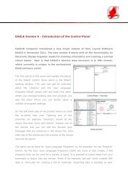
- The status bar of the editor window now contains indicators that show<br />
whether the drawing has been modified, and whether forward&backannotation<br />
is active.<br />
- The sheet thumbnails in the schematic editor now display the headline of<br />
the sheets' descriptions as their caption.<br />
- The sheet combo box in the schematic editor now displays the headline of<br />
the sheets' descriptions.<br />
- The context menu of the sheet thumbnails in the schematic editor has the<br />
new option "Description" which can be used to edit the description of a<br />
sheet.<br />
- If one editor window of a consistent board/schematic pair is closed, the<br />
remaining window now displays a warning that f/b annotation has been<br />
severed. You can click into that warning to hide it.<br />
- Show default command text buttons for DesignLink and PCB Service<br />
only in suitable editor windows (PCB Service only in board editor etc.).<br />
- If a limited edition of <strong>EAGLE</strong> can't perform a particular action, it now<br />
informs the user about the reason.<br />
- Added a note to the online help of the OPTIMIZE command, saying that this<br />
command is only applicable in a board, and that only signal wires can be<br />
selected.<br />
- PCB service ULP: Display quote parameters in dialog. Make country changeable<br />
(Service goes to Pentalogix or Eurocircuits depending on country).<br />
* Bugfixes:
- Group selection by polygon: Avoid selecting too much in special case.<br />
- PRINT command: Transfer options to print dialog if not ended with ';'.<br />
- CAM processor dialog: Avoid settings getting overridden from previously opened<br />
CAM file; Avoid crash after save and opening recent file.<br />
- ULP functions setgroup/ingroup: Bugfix if called for other editor window and no<br />
group defined yet.<br />
- ULP function dlgListView: No sorting for parameter sort=0.<br />
- ULP function dlgComboBox: Avoid jumping combobox size in special case (dlgRedisplay<br />
called).<br />
- Fix for wrong REPLACE with package and technology in special constellations.<br />
- Info dialog for arcs/wires: Correct handling of cap style while changing<br />
curve to 0/from 0.<br />
- Fixed updating sheet numbers in the ERRORS dialog when reordering,<br />
inserting or deleting sheets.<br />
- The frame object is now properly handled when rotated with the MOVE<br />
command. Note, though, that the orientation of letters and digits in the<br />
frame borders doesn't change when a frame is rotated.<br />
- Fixed handling "\n" in the eaglerc file.<br />
- Fixed handling ':' in file names under Linux and Mac OS X.<br />
- Fix wrong width calculation of Xref labels.<br />
- Fixed the online help for UL_AREA to correctly indicate that the area of<br />
a UL_PACKAGE or UL_SYMBOL in a UL_ELEMENT or UL_INSTANCE context includes<br />
the offset of the element/instance.<br />
- Fix wrong behaviour of toolbar extensions, in particular for text menus.<br />
- Fix for ULP function netget()/netpost() in case of Status 301 ("moved permanently"):<br />
Redirection if possible.<br />
- Fixed truncation of text descenders in command text buttons.