High Speed Machining Precision Tooling - Indobiz.biz
High Speed Machining Precision Tooling - Indobiz.biz
High Speed Machining Precision Tooling - Indobiz.biz

Create successful ePaper yourself
Turn your PDF publications into a flip-book with our unique Google optimized e-Paper software.
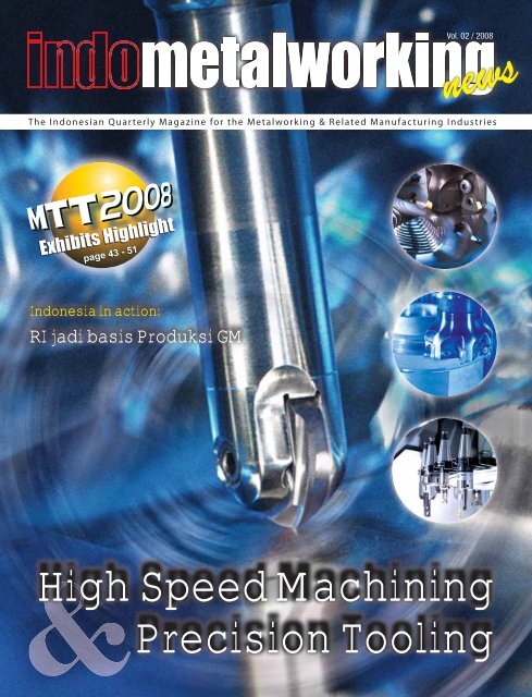
Vol. 02 / 2008<br />
news<br />
The Indonesian Quarterly Magazine for the Metalworking & Related Manufacturing Industries<br />
Indonesia in action:<br />
RI jadi basis Produksi GM<br />
<strong>High</strong> <strong>Speed</strong> <strong>Machining</strong><br />
<strong>Precision</strong> <strong>Tooling</strong>
e<br />
The Ind o n e s ian Qu a r terly Ma g a z ine for th e M e talwo rking & Re lated Ma n u fac turing Ind u s trie s<br />
The Indo n e sia n Qu a r terly Ma g a z ine for the Me tal wo r kin g & Re lated Ma n u fac t u r ing Ind u s tries<br />
The Ind o n e s ian Q u a r terly Ma g a z ine fo r th e Me tal working & Re lated Ma n u factu ring Ind u s trie s<br />
Contents<br />
Indonesia in action:<br />
RI jadi basis Produksi GM<br />
Indonesia in action:<br />
Vol. 02 / 2008<br />
news<br />
Indonesia in action:<br />
Vol. 02 / 2008<br />
news<br />
Vol. 02 / 2008<br />
news<br />
RI jadi basis Produksi GM<br />
RI jadi basis Produksi GM<br />
Hi<br />
On the Cover<br />
<strong>High</strong> <strong>Speed</strong> <strong>Machining</strong><br />
<strong>Precision</strong> <strong>Tooling</strong><br />
<strong>High</strong> <strong>Speed</strong> <strong>Machining</strong><br />
<strong>Precision</strong> <strong>Tooling</strong><br />
<strong>High</strong> <strong>Speed</strong> <strong>Machining</strong><br />
<strong>Precision</strong> <strong>Tooling</strong><br />
Automation<br />
Re-defi ning <strong>Precision</strong><br />
08<br />
38 Automation in a production shop<br />
The Art and Science of <strong>Precision</strong><br />
cutting Tools<br />
On Course with Xtra.tec ® Drills<br />
12<br />
16<br />
Shop Management<br />
41 Evaluating Shop Management System<br />
Events watch<br />
17<br />
Two for every eventuality<br />
Restructured boring and precision boring<br />
tools from WALTER<br />
43<br />
Indonesia Features<br />
KOIKE MONOGRAPH 1650<br />
Technical Features<br />
Revolution in Sheet-metal<br />
Manufacturing VPSS<br />
Industry & Technology<br />
18<br />
20<br />
52<br />
Industri masih figuran dalam pertumbuhan ekonomi<br />
Industri mesin perlu restrukturisasi<br />
Indonesia masih sulit, namun menjanjikan bagi<br />
bisnis mesin-mesin bekas<br />
Alternatif lebih murah mendapat sambutan<br />
Peraturan mempengaruhi struktur perdagangan<br />
Statistik denagn daya bukti terbatas<br />
Permintaan alat berat rekondisi meningkat<br />
Shrink Fit : The <strong>High</strong> Accuracy<br />
Toolholder of Choice<br />
Technology for Improving<br />
Five-Axis Capability<br />
The Road to Welding Automation<br />
Taking Rapid Prototyping<br />
to The Next Level<br />
Quality & Inspection<br />
Accuracy of Feed Axes<br />
Part Two<br />
Just how good is your<br />
process?<br />
22<br />
26<br />
28<br />
32<br />
34<br />
37<br />
Columns<br />
59 Just for the thought<br />
61 Fresh from the oven<br />
63 News Snippets<br />
65 Calendar of Events<br />
66 Jokes<br />
68 Quotes on work<br />
Indonesia In Action<br />
57<br />
Investasi Industri Elektronik US$2,5 Miliar<br />
RI jadi basis produksi GM<br />
Pemerintah proteksi industri alsintan<br />
RI kejar produksi 1 juta mobil<br />
4<br />
indometalworking news Vol. 2 / 2008
Editorial<br />
CUT TO THE CHASE – LET’S GO PRECISION<br />
Today, precision, productivity and production capability<br />
are the driving forces in every part of the world<br />
manufacturing. As tolerances get tighter and cycle<br />
times become the difference between profi t and loss, tool<br />
users need ever higher skills, equipment and solutions to<br />
be successful. The cutting tool industry is responding with<br />
new tools of their own: Advanced technology, education and<br />
collaboration.<br />
Over the past decade, Asian machine shops have been<br />
through a competitive gauntlet involving too little business<br />
to go around and relentless pressure from imports. Survival<br />
demanded exponentially greater productivity, an improvement<br />
only available with advanced tooling. In these plants, fewer<br />
operators ran more machines, leaving no time to nurse<br />
inferior tools through a day’s work. To survive, Indonesia<br />
industry had to concentrate on decreasing and/or eliminating<br />
machining operations and cycle times. The fi rms that have<br />
made improvements are now positioned to take advantage of<br />
economic changes that are creating new opportunities.<br />
For example, offshore outsourcing, one of the manufacturing<br />
trends over the past decade, is losing much of its luster as<br />
costs and complications reduce its appeal. The demands of<br />
growing Asian domestic economies have not only created<br />
competing demands for shipping, but resulted in rising costs<br />
for materials and energy and rising labor costs for contract<br />
manufacturers. Language barriers and the diffi culties of<br />
implementing in-process changes have taken their toll in<br />
production and delivery losses.<br />
European manufacturers have continued to invest in<br />
technology and successfully adapt to competitive pressures<br />
from all over the world. North America has the technology<br />
available to compete straight up with Asian and European<br />
competition, but needs better access to technology and<br />
supporting education. There is a disparity in the knowledge<br />
pool because mechanical engineers and machinists have not<br />
always had the resources at their disposal to keep up with<br />
new technologies in machining and cutting tools. But this is<br />
changing rapidly with the advent of new technology centers<br />
and closer working relationships between manufacturers and<br />
toolmakers.<br />
We can, and should, be making machined products in this<br />
country and we should be continuously adapting in the<br />
technologies required to make them more effi ciently and<br />
of higher quality. Sometimes, new technology is expensive,<br />
but it allows you to do things faster and more precisely. Over<br />
the past fi ve years, there has been a revolution in Indonesia<br />
manufacturing based on the ability to make things faster and<br />
more cost effectively. We are poised for a similar revolution<br />
in machining. This is why education in the latest advances in<br />
tooling, materials, parts design and CNC machining is vital to<br />
our industry.<br />
Recognizing the importance of demonstrating the value<br />
of advanced tooling and machining methods, cutting<br />
tool manufacturers are reaching out to the users of their<br />
products, inviting them to make their requirements known<br />
and collaborating with them on creating solutions and<br />
demonstrating the value of new technologies and methods.<br />
By investing in technical education, and advanced tool<br />
development for the latest machining methods, we are<br />
helping Indonesia tool up for future success.<br />
Edwin Widjaja<br />
Editor in Chief<br />
PT IndoBiz Connection<br />
Gedung Hero II 8 th fl oor<br />
Jl. Gatot Subroto Kav. 64 No. 177A Jakarta Selatan - Indonesia<br />
Telp. : +62-21-657 00 022<br />
Fax : +62-21-266 45 463<br />
Contact :<br />
Melissa Ng<br />
Edwin Widjaja<br />
sales@indo<strong>biz</strong>.<strong>biz</strong> (advertisement)<br />
editor@indo<strong>biz</strong>.<strong>biz</strong> (articles/editorial)<br />
All rights reserved. No Portion<br />
of this publication covered<br />
by the copyright herein may<br />
be reproduced in any form or<br />
means - graphic, electronic,<br />
mechanical, photocopying,<br />
recording, taping, etc -<br />
without the written consent<br />
of the publisher. Opinions<br />
expressed by contributors and<br />
advertisers are not necessarily<br />
those of the publisher and<br />
editor. All of the articles are<br />
based on the original author.<br />
6<br />
indometalworking news Vol. 2 / 2008
Re-defining<br />
<strong>Precision</strong><br />
It’s important not to limit the defi nition<br />
of precision to one in particular, but<br />
instead expand the defi nition to three<br />
unique precision types: micro precision,<br />
ultra precision and nano precision.<br />
If you were to Google “precision<br />
machining,” the results would be<br />
staggering with more than a half million<br />
hits. If you were to narrow the search with<br />
“precision milling,” the results would be<br />
far less with roughly 41,000 hits. Still<br />
that seems to be an awful lot of hits and<br />
we don’t even know if the hits pertain to<br />
actual machine shops or not. However,<br />
if you were to dig further into the results<br />
and visit many of the actual machining<br />
Web sites from those results, you would<br />
be amazed at the number of companies<br />
that call themselves a precision shop<br />
with no clear indication of what defi nes<br />
them as a precision manufacturer. Some<br />
of these companies go beyond the word<br />
precision and defi ne themselves as<br />
military precision, medical precision<br />
or commonly Swiss precision. So the<br />
question is: What defi nes precision<br />
today?<br />
Defining <strong>Precision</strong><br />
A clear defi nition is needed to uniquely<br />
identify the best in class shops in a<br />
highly competitive market. Because the<br />
market spans over a very broad range<br />
of industries, it’s rather important not to<br />
limit the defi nition to one in particular,<br />
but instead expand the defi nition to<br />
three unique precision types.<br />
These types can be identifi ed as micro<br />
precision, ultra precision and nano<br />
precision.<br />
By these three types, precision can be<br />
identifi ed in regards to the technology<br />
that a shop might have and what you can<br />
expect in quality and accuracy instead<br />
of using a generic term as precision.<br />
Further, each precision type also can<br />
be used to defi ne the technology and<br />
expectations within a machine tool<br />
and can be further used to defi ne the<br />
maximum part quality that can be<br />
expected of the machine without over<br />
complicating things.<br />
<strong>Precision</strong> can now be narrowed to micro<br />
precision as precision defi ned by ±5<br />
microns or less on the workpiece; ultra<br />
precision as precision defi ned by ±2.5<br />
microns or less on the workpiece; and,<br />
nano precision as precision defi ned by 1<br />
micron or less on the workpiece.<br />
Understanding Microns<br />
As you can see we’re no longer talking<br />
in terms of English units, but instead<br />
talking in terms of Metric units. This<br />
method is not only clearer but simpler<br />
to work with than thousands, tenths<br />
or millionths. Working with microns<br />
also is a universally understood unit of<br />
measurement and is clearly known and<br />
widely accepted around the world.<br />
It allows us to defi ne closer tolerances<br />
much easier. For example, rather than<br />
saying 40 millionths or .00004” it is<br />
much easier to say 1 micron or 1 um.<br />
Chart 1 will provide you with a clear<br />
illustration of equivalent units.<br />
In re-defi ning precision, it’s important<br />
to understand the micron unit. There<br />
are several reasons why. First, it gives<br />
a better picture of the three types of<br />
precision.<br />
Secondly, it brings the manufacturing<br />
world in line with the advance technology<br />
that is available on the market today—<br />
from the machine tool to inspection<br />
equipment. Additionally, it articulates<br />
the trends in product designs toward<br />
closer tolerances and miniaturization.<br />
8<br />
indometalworking news Vol. 2 / 2008
Chart 1 Unit Equivalent<br />
Metric to Imperial Equivalent<br />
10 microns<br />
5 microns<br />
1 micron<br />
1 micron<br />
Average Hair diameter<br />
Red Blood Cells<br />
Chart courtesy of Kern <strong>Precision</strong>, Inc<br />
Moving Beyond the Pack<br />
= .0004 inches, UPM<br />
= .0002 inches, MPM<br />
= .00004 inches, NPM<br />
= 1000 nanometers<br />
= 60 microns<br />
= 20 microns<br />
Embracing technology is necessary for<br />
survival in U.S. manufacturing today.<br />
Current machine tool technology has<br />
lowered the bar toward ultra and nano<br />
precision. Once only visible in the lab,<br />
ultra and nano precision technology<br />
has now moved from the lab and R&D<br />
centers to the commercial sector.<br />
Although much of the core technology<br />
in today’s ultra precision machining<br />
(UPM) is not new, it’s the combination of<br />
the improved elements and the careful<br />
systematic unity that has pushed the<br />
technology into a new direction of ultra<br />
precision. Further, the tools used to<br />
bring everything together have also<br />
improved greatly.<br />
To illustrate this, consider the secondary<br />
equipment used to build a Ferrari, a<br />
Lamborghini or perhaps a Lotus. These<br />
unique manufacturers use state-of-theart<br />
equipment to build their cars ensuring<br />
performance and quality. Likewise,<br />
machine tool builders who claim micro,<br />
ultra and nano precision tolerances use<br />
a similar approach by using state-of-theart<br />
technology to build state-of-the-art<br />
machine tools.<br />
Additionally however, machine tool<br />
builders offering these tolerances<br />
need to be extremely concerned with<br />
their surrounding environment, which<br />
includes cleanliness, organization,<br />
air quality and temperature control.<br />
Bringing micro, ultra and nano precision<br />
into the shop and being successful with<br />
it also requires the same approach and<br />
the same high quality environment.<br />
Traditionally reserved for grinding,<br />
nano precision is no longer just limited<br />
to grinding and has now entered the<br />
commercial sector for milling. A nano<br />
precision milling machine offers a<br />
host of new opportunities—ranging<br />
from hard milling for the mold and die<br />
industry to jig grinding holes for mold<br />
bases. By nature, a nano precisioncapable<br />
machine along with superior<br />
build characteristics is going to produce<br />
extraordinary surface fi nishes.<br />
Therefore the possibilities to hold ±1<br />
micron on drilling and milling features<br />
on your parts and holding surface<br />
fi nishes of values of Ra 0.05um are now<br />
achievable. In the past these kinds of<br />
tolerances and surface fi nishes were<br />
only possible in a lab environment on<br />
Figure 1<br />
specially designed machines with a<br />
very small work envelope. In fact today,<br />
workable envelopes as large as 20” x<br />
20” x 15” are possible in a commercial<br />
environment.<br />
Although there’s really no practical<br />
application, Figure 1 shows a hole that<br />
was drilled in a 60-micron diameter<br />
human hair using ultra and nano<br />
precision machining. What should be<br />
a clear observation, the hole has a<br />
very clean and well-defi ned entrance<br />
indicating the preciseness and<br />
Figure 2<br />
smoothness of the drilling motion. The<br />
drill diameter was 30 micron or a little<br />
over .001” diameter and its size is not<br />
visible to the naked eye.<br />
Figure 2 shows an aluminum optical<br />
tool that was diamond milled to a mirror<br />
fi nish using the same milling machine<br />
technology, but equipped with an<br />
ultra precision dividing head. Further,<br />
small to medium size molds as well as<br />
micromolds can also experience similar<br />
results by using ultra and nano precision<br />
machining: UPM and NPM.<br />
Manufacturers that use such advanced<br />
equipment are capable of meeting<br />
the higher demands of new product<br />
designs, tighter tolerance requires and<br />
lower labor cost through a decrease<br />
in part handling by increasing surface<br />
fi nish quality. By investing in the<br />
latest technology, manufacturers can<br />
truly identify themselves as a best in<br />
class micro, ultra or nano precision<br />
manufacturer, and therefore move<br />
beyond the pack.<br />
Behind the Technology<br />
Nano technology within a milling machine<br />
can bring a lot of skepticism. Holding<br />
±1 micron or ±1000 nanometers while<br />
obtaining surface fi nishes of Ra 0.05um,<br />
should certainly be questioned. Anyone<br />
with any experience in holding tight<br />
tolerances should have some doubts<br />
about these capabilities, but rest<br />
indometalworking news Vol. 2 / 2008 9
assured the technology is available and<br />
results are astounding.<br />
Similar to high-speed machining, nano<br />
precision machining or NPM requires<br />
a complete circle of technologies that<br />
complement each other. NPM shouldn’t<br />
be considered machining at slow feeds<br />
and speeds in order achieve closer<br />
tolerances but rather the opposite.<br />
Using HSM practices is actually one<br />
of the center points of NPM where<br />
as HSM doesn’t guarantee precision.<br />
The primary focus in achieving nano<br />
precision tolerances on your parts is<br />
centered on the machine tool itself.<br />
On the other, your CAD/CAM system<br />
must be able to handle the increased<br />
tolerance output requirements and this<br />
would include surface tolerances.<br />
Figure 3<br />
One of the key ingredients of the<br />
machine tool for NPM is the drive system:<br />
hydrostatic drives and guideways.<br />
This drive and guideways technology<br />
uses a very small yet very controlled fi lm<br />
of oil between the surfaces of the two<br />
guideways and between the ball screw<br />
(see Figure 3) and nut thus producing no<br />
metal-to-metal contact in the motion.<br />
This ultimately removes almost all<br />
kinetic and static friction from the drive<br />
system producing the most precise<br />
motion possible.<br />
Another important aspect is the ability<br />
to control heat within the entire machine<br />
Figure 4<br />
tool. A polymer-base machine tool is<br />
the start of precision, but to achieve<br />
even better results every aspect of the<br />
machine tool needs to be completely<br />
temperature controlled. This would<br />
include the table area, spindle, coolant,<br />
electrical cabinet and the fl uids for the<br />
hydrostatic drive and guideways system<br />
(see Figure 4).<br />
Glass scales are also part of a precision<br />
machine tool, but it’s important to<br />
realize that the fi nest in precision glass<br />
scale must be used—such as .1 micron<br />
or 100 nano precision intervals. Some<br />
other important factors to consider are<br />
Figure 5<br />
the precision quality and location of the<br />
tool laser measurement system, the<br />
spindle’s ability to exchange the cutting<br />
tools in the same exact consistent<br />
location and an ultra precision HSK<br />
spindle with near zero runout. This in<br />
combination with the other systems<br />
within the machine tool will no doubt<br />
provide you with the ability to achieve<br />
nano precision (see Figure 5).<br />
Quality Assurance Infrastructure<br />
NPM doesn’t stop at the machine tool.<br />
Having the technology and the quality<br />
assurance infrastructure to check<br />
such precise parts is quite important.<br />
Coordinate measurement systems and<br />
3-D vision inspection systems have<br />
been able to stay ahead of the advances<br />
in precision machine tool technology.<br />
Some of today’s fi nest CMMs have the<br />
ability of measuring uncertainties of<br />
250 nano meters at a resolution of 7.5<br />
nano meters.<br />
Additional, 2-D vision systems now have<br />
the ability to measure depths. Equipped<br />
with a combination-touch probe, laser<br />
and white light sensors, vision systems<br />
have taken vision inspection into a 3-D<br />
world. White light sensor technology for<br />
probing has reached into the submicron<br />
level by splitting pixels into thirds.<br />
To ensure your nano parts are indeed<br />
nano precise, understanding your<br />
quality assurance infrastructure is just<br />
as important as your nano precision<br />
machining infrastructure. If the two<br />
technologies work together, re-defi ning<br />
your precision will move you toward the<br />
ability to reclaim your position as a real<br />
precision manufacturer producing near<br />
perfect parts.<br />
10<br />
indometalworking news Vol. 2 / 2008
The Art And Science Of<br />
<strong>Precision</strong> Cutting Tools<br />
Machine tools become<br />
faster and more stable<br />
while cutting tools get<br />
tougher, longer lasting<br />
and geometrically more<br />
complex. I visited the<br />
web of few premier<br />
cutting tool manufacturer<br />
to look at the state<br />
of the art of making<br />
carbide cutting tools<br />
that complement today’s<br />
machine tool technology<br />
Interested in the precision cutting<br />
tools story, I tracked down every<br />
cutting tools manufacturer to see<br />
the story behind the making of precision<br />
cutting tools and the impact of usage<br />
today.<br />
I hooked up for a quick breeze surfi ng<br />
through the net, and ending up at a<br />
few characteristics that made a new<br />
precision cutting tools story of today<br />
generation. It was a perfect afternoon<br />
for me to write this article with the start<br />
of one company in Germany.<br />
Keeping Ahead Of The Curve<br />
Horn of Germany started business in<br />
1969 specializing in grooving tools<br />
for piston production. Being close to<br />
the automotive industry in Stuttgart<br />
makes the Tübingen location ideal for<br />
serving this market segment. According<br />
to website, the company quickly<br />
established a good reputation for<br />
technology and consistency and began<br />
to grow its product offering.<br />
Horn has managed to stay under the<br />
radar screen of many larger competitors<br />
by positioning themselves more as a<br />
custom tool manufacturer rather than<br />
an off-the-shelf commodity vendor. Their<br />
average batch run is about 70 pieces<br />
and at those volumes, they need to be<br />
smart about manufacturing our cutters<br />
as well as designing specifi c customer<br />
solutions.<br />
To this end, the company uses a<br />
two-prong strategy for its product<br />
development. In addition to developing<br />
new grades, coatings and geometries<br />
for its carbide inserts and solid carbide<br />
tools, the company works hard at its<br />
manufacturing capability as well.<br />
How To Cook An Insert<br />
The indexable insert is a remarkable<br />
piece of technology. Out of an<br />
apparently simple composite primarily<br />
made from two components—a binder<br />
and “powder”—comes a variety of<br />
grades, shapes, sizes and performance<br />
characteristics that help metalworking<br />
manufacturers get the most from their<br />
processes.<br />
Often compared to baking a cake, the<br />
12<br />
indometalworking news Vol. 2 / 2008
ecipe for manufacturing indexable<br />
carbide inserts that deliver the desired<br />
performance characteristics is a function<br />
of the ratios among base components. In<br />
its simplest form, to increase an insert’s<br />
toughness (its resistance to fracture), the<br />
binder content-to-powder ratio is raised.<br />
To create a harder cutting material, the<br />
ratio is lowered, with more powder and<br />
less binder, which vmakes the cutter<br />
grades of carbide substrates refl ect<br />
a sliding scale between the extremes<br />
of toughness and hardness, which are<br />
matched to a given application.<br />
Mixing the binder and powder is a<br />
critical step in the manufacture of<br />
indexable insert tools. Like a “heat”<br />
in steel production, each batch of the<br />
recipe for a given base grade is carefully<br />
controlled for consistency.<br />
After mixing, the “batter” is pressed<br />
into a shape. The pressing process<br />
uses insert molds to impart the insert<br />
shape and some of the geometry, such<br />
as chipbreakers, onto the now “green”<br />
insert.<br />
In addition to the conventional pressing<br />
technology used by most insert<br />
producers, there is a successfully<br />
developed method of injection molding<br />
inserts as well. This gives the user the<br />
ability to mold complex inserts much<br />
closer to a fi nal shape and complete<br />
forms that would be almost impossible<br />
by conventional technology. In turn, it<br />
reduces the amount of grinding required<br />
to achieve a fi nished geometry and<br />
speeds the throughput.<br />
The details of this process are<br />
proprietary, but consist basically of<br />
adding a compound to the binder/<br />
powder mix so it can fl ow under pressure<br />
through gates into a closed mold cavity.<br />
This fl owable material is also extruded<br />
into tooling blanks that become the basis<br />
for some of the company’s solid carbide<br />
products. In the next manufacturing<br />
step, which is sintering, this additional<br />
compound vaporizes leaving no trace in<br />
the fi nal insert grade.<br />
Sintering is the last processing step<br />
before a green insert blank becomes<br />
the rugged carbide substrate that shops<br />
are familiar with. Using the cake-baking<br />
analogy, this step represents the oven.<br />
Under a vacuum at high temperature, the<br />
green insert is heated until the binder<br />
plasticizes, enabling it to fl ow around<br />
the grains of powder fi lling the voids.<br />
Upon cooling, the binder and grains are<br />
chemically and physically linked into a<br />
uniform matrix.<br />
On The Shop Floor<br />
Out of the oven, the inserts are ready<br />
to be machined to their fi nal shapes,<br />
geometry and precision. The shop fl oor<br />
refl ects this rationalization concept.<br />
The grinding department is arranged<br />
in rows of autonomous cells. Four of<br />
these cells are operated by one person.<br />
Each cell is built around a DMG milling<br />
machine converted to grind inserts. In<br />
the machine spindle, an arbor is used<br />
to hold various superabrasive wheels<br />
and brushes allowing all of the grinding<br />
operations to be performed in sequence<br />
without changing wheels.<br />
An automated load/unload system shall<br />
be designed and feeds the machine<br />
tools. As a fi nished insert is removed<br />
from the work zone, it passes through a<br />
laser gaging system that checks critical<br />
dimensions. This cellular concept is<br />
duplicated at every manufacturing<br />
company nowadays.<br />
While the cells are not dedicated to a<br />
specifi c cutting tool product, they are<br />
tooled to accommodate like families<br />
of inserts. It should have several types<br />
of cells to accommodate various insert<br />
parameters. The production schedule is<br />
made up to run similar jobs sequentially,<br />
which simplifi es change-over from one<br />
insert to another. Generally, only the<br />
material handling devices and gaging<br />
units need to be physically adjusted.<br />
To do own insert coating it shall use a<br />
PVD (physical vapor deposit) system.<br />
Inserts to be coated are fi rst cleaned in<br />
an automated (no-touch) batch washing<br />
system. The clean inserts are assembled<br />
into racks for placement in the coating<br />
chamber. Three different coatings can<br />
be used individually or layered.<br />
1. <strong>Precision</strong> 1 : To expedite the grinding process,<br />
an arbor with various wheels and brushes is used<br />
in the grinding cell. The arbor is supported by a<br />
dual contact V-flange connector<br />
2. <strong>Precision</strong> 2: In addition to sintering its own<br />
inserts, the company also uses a PVD process to<br />
coat various insert grades. The racks on the left<br />
are shown prior to coating, and the racks on the<br />
right have been processed.<br />
3. <strong>Precision</strong> 3: Insert grinding is arranged in<br />
cells. These are comprised of converted milling<br />
machines set up to grind inserts. Load/unload and<br />
inspection is automated, enabling one operator to<br />
oversee four cells<br />
indometalworking news Vol. 2 / 2008 13
Planning For The Future<br />
While the manufacturing system for<br />
insert production is proven, every<br />
company shall continue to develop new<br />
process technologies for precision parts<br />
making. Keeping ahead of the curve is<br />
an ongoing process. ew<br />
TIPS<br />
Tips For Choosing The Right Cutter<br />
There are many choices that one must<br />
consider when picking the correct<br />
cutter and insert for an application.<br />
The following article is a brief rundown<br />
of applications involving grooving and<br />
turning with a focus on OD grooving.<br />
Cutting grooves can be one of the most<br />
diffi cult jobs for a turning operation, and<br />
the geometries for these applications<br />
can be some of the most complex. In<br />
a typical grooving operation, forces are<br />
potentially facing both a radial and axial<br />
direction, cutting with the main cutting<br />
edge (sometimes fully engaged and<br />
sometimes partially engaged) as well as<br />
cutting on one or both of the side cutting<br />
edges.<br />
Depending on the operation, an operator<br />
may be using an insert with a sintered<br />
top rake geometry (usually the width<br />
of the groove will be the determining<br />
factor). For grooves that are too narrow,<br />
sintered top rake geometry is not<br />
possible. Full width generally is the<br />
best solution for providing chip control.<br />
However, how does one determine the<br />
correct geometry?<br />
Groove Width<br />
Is the groove that is needed equal to a<br />
standard grooving insert width offered<br />
by a grooving tool manufacturer?<br />
(See Fig. 1.)<br />
If so, generally cutting forces will be only<br />
on the main cutting edge. In this case,<br />
you will be looking for a grooving insert<br />
that will reduce the width of the chip<br />
(form the chip away from the sides of<br />
the groove) to achieve a better fi nish on<br />
the groove side walls. (See Fig. 2.)<br />
If not, the options are to cut on the full<br />
face, and then a partial face (see Fig. 3),<br />
or place axial forces on the insert in a<br />
turning fashion (see Fig. 4). Either way,<br />
choosing the geometry that provides<br />
the best fi nish and most effective<br />
chipbreaking becomes more diffi cult.<br />
When choosing the geometry of the<br />
tool, it is important to choose a positive<br />
cutting geometry and understand the<br />
operation being performed.<br />
If the groove width matches the insert<br />
width, the choices are much easier. You<br />
must now determine the aggressiveness<br />
of the chip formation in relation to the<br />
tensile strength of the material being<br />
cut. If you look at the two chip formers<br />
(see Fig. 5), you will see that the distance<br />
from the front edge to the back edge<br />
varies in length.<br />
The longer length will provide a<br />
smoother cut, but will create a larger<br />
watch spring chip. If the tensile strength<br />
is too low, this watch spring may become<br />
uncontrollable, and the chip may pigtail.<br />
The shorter length will produce a much<br />
tighter watch spring, but if the tensile<br />
strength is too high, chip forces may<br />
damage the main cutting edge.<br />
If the groove width is wider than the<br />
insert width, multiple plunges can be<br />
performed to create the wider groove or<br />
you may plunge and turn the groove.<br />
If you choose to perform multiple<br />
plunges, the easiest way is to take the<br />
fi rst plunge and then step over 50 to 75<br />
percent of the insert width and plunge<br />
again, repeating until the desired groove<br />
width is reached. This is the easiest to<br />
program. However, cuts using only 50<br />
to 75 percent of the groove width can<br />
make chip control diffi cult. If a full cut is<br />
performed, you are collapsing the chip<br />
from both sides onto itself. When taking<br />
a partial cut, you are collapsing the<br />
chip from one direction only, and this<br />
can result in pigtails or unmanageable<br />
chips.<br />
One simple method, using the multiple<br />
plunge process, is to take as many<br />
full cuts as possible, and then cut the<br />
remaining material on the center of the<br />
insert. This uses all of the advantages of<br />
a simple chip former.<br />
For a plunge and turn operation, it’s<br />
Figure 1<br />
Figure 3 Figure 4<br />
Figure 2<br />
14<br />
indometalworking news Vol. 2 / 2008
est to use a chip former that tries to<br />
reduce the chip from the front and also<br />
provides an area on the side of the<br />
insert to control the chip. This requires<br />
more complex programming because<br />
when approaching the bottom of the<br />
groove, material should not be removed<br />
from both the front of the insert and the<br />
side of the insert at the same time. This<br />
will usually damage the insert and the<br />
toolholder.<br />
“Impossible to break the chip” material:<br />
These materials are usually forgings,<br />
carbon and alloy steel of very low tensile<br />
strength carbon and alloy steels, as well<br />
as some tubing material.<br />
In these materials, very aggressive<br />
chipbreakers are required, and in some<br />
instances, a programmed peck cycle is<br />
necessary. Never retract more than the<br />
feed rate per revolution; otherwise you<br />
can pinch a chip between the cutting<br />
edge and the material.<br />
In addition, cutting an ID groove, face<br />
groove and/or form groove follows<br />
these same basic principles, but each<br />
provides its own characteristics.<br />
Material<br />
Figure 5<br />
What type of material is being cut?<br />
These tips are not always 100 percent<br />
accurate, but they provide a good rule<br />
of thumb.<br />
Short chipping material: This is usually<br />
the easiest way to control the chip, and<br />
the chipbreaker is the least important.<br />
However, a strong cutting edge will<br />
be required. The shortest chipping<br />
materials are cast irons, hardened steels<br />
and brass. With these operations, the<br />
groove width is usually not as important<br />
because the chips are easy to control.<br />
Long chipping material: This is where<br />
the largest amount of materials will fall.<br />
The long chipping group could be subgrouped<br />
into different categories. Long<br />
chipping materials include most carbon<br />
steels, alloy steels, stainless steels and<br />
exotics.<br />
The longer length will provide a<br />
smoother cut, but will create a larger<br />
watch spring chip. If the tensile strength<br />
is too low, this watch spring may become<br />
uncontrollable, and the chip may pigtail.<br />
The shorter length will produce a much<br />
tighter watch spring, but if the tensile<br />
strength is too high, chip forces may<br />
damage the main cutting edge.<br />
If the groove width is wider than the<br />
insert width, multiple plunges can be<br />
performed to create the wider groove or<br />
you may plunge and turn the groove.<br />
If you choose to perform multiple<br />
plunges, the easiest way is to take the<br />
fi rst plunge and then step over 50 to 75<br />
percent of the insert width and plunge<br />
again, repeating until the desired groove<br />
width is reached.<br />
This is the easiest to program. However,<br />
cuts using only 50 to 75 percent of the<br />
groove width can make chip control<br />
diffi cult. If a full cut is performed, you are<br />
collapsing the chip from both sides onto<br />
itself. When taking a partial cut, you are<br />
collapsing the chip from one direction<br />
only, and this can result in pigtails or<br />
unmanageable chips.<br />
One simple method, using the multiple<br />
plunge process, is to take as many<br />
full cuts as possible, and then cut the<br />
remaining material on the center of the<br />
insert. This uses all of the advantages of<br />
a simple chip former.<br />
For a plunge and turn operation, it’s<br />
best to use a chip former that tries to<br />
reduce the chip from the front and also<br />
provides an area on the side of the<br />
insert to control the chip. This requires<br />
more complex programming because<br />
when approaching the bottom of the<br />
groove, material should not be removed<br />
from both the front of the insert and the<br />
side of the insert at the same time. This<br />
will usually damage the insert and the<br />
toolholder.<br />
“Impossible to break the chip”<br />
material: These materials are usually<br />
forgings, carbon and alloy steel of very<br />
low tensile strength carbon and alloy<br />
steels, as well as some tubing material.<br />
In these materials, very aggressive<br />
chipbreakers are required, and in some<br />
instances, a programmed peck cycle is<br />
necessary. Never retract more than the<br />
feed rate per revolution; otherwise you<br />
can pinch a chip between the cutting<br />
edge and the material.<br />
In addition, cutting an ID groove, face<br />
groove and/or form groove follows<br />
these same basic principles, but each<br />
provides its own characteristics.<br />
When choosing the geometry of the<br />
tool, it is important to choose a positive<br />
cutting geometry and understand the<br />
operation being performed.<br />
If the groove width matches the insert<br />
width, the choices are much easier. You<br />
must now determine the aggressiveness<br />
of the chip formation in relation to the<br />
tensile strength of the material being<br />
cut. If you look at the two chip formers<br />
(see Fig. 5), you will see that the distance<br />
from the front edge to the back edge<br />
varies in length.<br />
indometalworking news Vol. 2 / 2008 15
Press Release<br />
On Course with Xtra.tec ® Drills<br />
WALTER launches new Xtra.tec ® insert drill<br />
The tried and tested Xtra.tec ® drill product line B40xx<br />
exchangeable tip has been extended by indexable<br />
insert drills. The new Xtra.tec ® insert drills are<br />
launched under the designation B4213 for drilling depths<br />
up to 3xD. Other types and lengths are being planned. While<br />
exchangeable tip allow highest feed rates, the indexable<br />
insert series is characterized by low cutting materials<br />
costs (four cutting edges per insert) as well as an extended<br />
application range such as transversal spot-drilling, cross<br />
drilling or drilling on convex faces. In order to ensure a<br />
better differentiation between the two tools, the B40xx<br />
drills will be launched under the name Xtra.tec ® point<br />
drills.<br />
As with all its Xtra.tec ® tools, WALTER has again made<br />
best use of their engineering expertise in developing this<br />
Xtra.tec ® drill. The inner and outer inserts have a special<br />
design. The inner insert provides for centering, the<br />
outer one, equipped with wiper geometry, for maximum<br />
precision and good surface qualities. The helical tool<br />
shank ensures excellent chip fl ow. For the various<br />
applications, universal Tiger.tec ® or PVD-Tiger.tec ®<br />
cutting materials are available, the latter especially<br />
for the processing of high-alloyed stainless steels.<br />
Currently, the new Xtra.tec ® insert drills are available in<br />
the diameter range 21 to 29 mm, but Walter is already<br />
planning to extend the range downwards step by step to<br />
14 mm, as well as to enlarge the indexable insert product<br />
line.<br />
About Xtra.tec ®<br />
WALTER’s Xtra.tec ® product line sets a benchmark<br />
in the carbide insert sector. Compared to standard<br />
tools, productivity can be increased by up to 100%,<br />
due to the following developments: The inserts are<br />
manufactured from high-performance optimized<br />
Tiger.tec ® cutting materials, and the favorable<br />
hardness/toughness parameters ensure maximum<br />
cutting performance. The geometries of the inserts<br />
are highly positive. The consequences are extremely<br />
soft cuts, excellent surface quality and low impact on<br />
machine and clamping. The hard nickel plated<br />
surface of the tool bodies with their optimum<br />
design ensure an improved chip fl ow and long insert life.<br />
Together, all these characteristics ensure an increase in<br />
productivity as well as maximum process reliability. Furthermore,<br />
the universal applicability for all cast iron, steel<br />
and stainless steel grades, as well as a high number of<br />
cutting edges (depending on the tool type) reduce tool<br />
costs.<br />
Fig.: Xtra.tec ® insert drill B4213<br />
BU: The Xtra.tec ® insert drill with special four-edged inner and<br />
outer inserts extends WALTERs Xtra.tec ® product line.<br />
16<br />
indometalworking news Vol. 2 / 2008
Two for every eventuality<br />
Restructured boring and precision boring<br />
tools from WALTER<br />
To simplify handing for users, WALTER has restructured<br />
its tooling systems for boring and precision boring and<br />
changed the designations it uses. Its two-fl ute boring<br />
tools are now called WALTER Boring MEDIUM (working range<br />
between 20-153mm) and WALTER BoringMAXI (working<br />
range between 150-640mm). There is a widely diverse<br />
selection of indexable inserts available for the two<br />
boring tools, making use of different cutting materials and<br />
positive geometries. These cover the entire spectrum of<br />
metal materials for coarse to medium machining operations.<br />
WALTER Boring MEDIUM comes with NTC modular and<br />
ScrewFit adapters in cartridge versions for CC and WC shaped<br />
ISO indexable inserts. Both the adapter systems are short<br />
and consequently stable, affording outstanding concentricity<br />
properties and process reliability, even under diffi cult<br />
application conditions such as inclined boreholes, stepped<br />
boreholes, spectacle-shaped bores and so on. Positive<br />
locking cartridge fi xtures prevent lift-off or<br />
displacement even in this type of situation. The large<br />
diameter range of the WALTER Boring MAXI is implemented<br />
using an exchangeable bridge module.<br />
The single-fl uted precision boring tools WALTER<br />
<strong>Precision</strong> MEDIUM und WALTER <strong>Precision</strong> MAXI have also<br />
been restructured. As their new designation suggests, these<br />
have now been adapted in line with the boring tools in terms<br />
of their diameter graduations and working ranges. The<br />
WALTER <strong>Precision</strong> MEDIUM series additionally offers<br />
automatic imbalance compensation, permitting cutting<br />
speeds of up to 2000 m/min. Both WALTER precision<br />
tools permit backlash-free precision nonius setting up to<br />
precisely 0.002 mm. For special precision machining<br />
operations, alongside carbide industrial inserts, CBN and<br />
PCD cutting materials with a positive geometry are also<br />
available.<br />
As both the WALTER Boring and WALTER <strong>Precision</strong><br />
series have the same external dimensions, they offer two<br />
additional benefi ts which should not be underestimated:<br />
Firstly the programming input is reduced, and secondly no<br />
separate collision checks need to be performed. Accessories<br />
such as adapters, extensions and so on are also identical.<br />
Xtra.tec ® For precision processing of even smaller<br />
diameters, users are able to call upon the WALTER<br />
<strong>Precision</strong> MINI system (working range 2-45mm). These tools<br />
are fi tted with boring bars in a solid carbide or indexable<br />
insert version. Here too, manual imbalance compensation<br />
permits cutting speeds of up to 2000m/min. Setting<br />
accuracy is also around 0.002mm.<br />
Boring tools / precision tools<br />
The new boring and<br />
precision boring tools<br />
WALTER BoringMEDIUM and<br />
WALTER Boring MAXI /<br />
WALTER <strong>Precision</strong>MEDIUM<br />
and WALTER <strong>Precision</strong> MAXI<br />
have been formed to create<br />
a real tooling family:<br />
Dimensionally coordinated, they<br />
simplify handling and reduce the<br />
input required for programming and collision<br />
control. (picture: WALTER AG)
Technical Features<br />
Automation in the cutting process provides the cutting edge to<br />
Heating Ventilation Air-Conditioning ( HVAC ) industry in Indonesia.<br />
“ Cutting it productively ” every time is the key to automation<br />
success<br />
Every time a shopping mall , an offi ce tower or high rise building pops<br />
up in downtown Jakarta, have you ever wondered how the builders<br />
managed to put up all the sheet metal ducting for air-conditioning<br />
and ventilation so effi ciently? Automation in cutting and accuracy in<br />
fi t up of joints had made it possible.<br />
Some of the products that he is fabricating can<br />
be seen below.<br />
In the past skilled workers had to manually cut the sheet metal<br />
with heavy duty scissors and then knock them into a shape with a<br />
hammer before joining them up to form an air-con ducting for each<br />
fl oor of the building. This process was very skill dependent, labours<br />
intensive, time consuming and results in much waste of materials.<br />
Because it was manually done there were many reworks and rejects<br />
of workpieces which slows the building completion.<br />
Koike Sanso Kogyo Co. Ltd., the world’s leading manufacturer of<br />
cutting machineries, have provided the local contractors with a<br />
portable cutting solution and the cutting edge tool to compete<br />
effectively. The KOIKE MONOGRAPH 1650 CNC Plasma cutting<br />
machine for thin sheet cutting was designed to be a compact,<br />
unitized and portable machine so that it can be transported to the<br />
construction site. This means large cost savings in transportation<br />
for the completed ducting , since all cutting work can now be done<br />
in the basement car park on site. Because the machine is available<br />
on site, any last minute changes can be accommodated easily and<br />
swiftly.<br />
KOIKE MONOGRAPH 1650 CNC Plasma cutting machine for thin<br />
sheet cutting<br />
According to a HVAC contractor he has achieved much savings from<br />
the following:<br />
- Reduced transportation costs from the factory to the<br />
construction site because all cutting are done on site and on<br />
demand.<br />
- Material savings because computer controlled nesting of<br />
parts had resulted in less wastage, rejects and reworks.<br />
- Less reliance on limited skill labour as the machine<br />
provides the technology and automation, only a general<br />
worker can operate the machine and achieve accurate<br />
cuts everytime.<br />
- Last minute changes of work pieces can be easily<br />
accommodated and completed on the same day.<br />
- Project completion can be achieved at a shorter time span.<br />
- More projects can be under taken as a result of the<br />
cutting productivity.<br />
Computer nested parts are accurately cut.<br />
Cutting with rolled sheets reduces<br />
wastages.<br />
He realised that to compete with foreign contractors who have<br />
invested in high technologies and automatic cutting and forming<br />
equipment, he too must upgrade himself or be force out of<br />
business.<br />
In this era of globalisation Indonesia contractors must upgrade<br />
themselves and fi nd new ways of doing things in order to compete.<br />
Compact , Unitized and transportable Monograph 1650.<br />
18<br />
indometalworking news Vol. 2 / 2008
Revolution in Sheet-metal<br />
Manufacturing VPSS<br />
Amada’s guiding principle: “Amada<br />
grows with the voices of our customers<br />
and advances with our customers.” As<br />
such, we at Amada are well aware that<br />
today’s manufacturing industries are<br />
becoming very tough and our customers<br />
have to fi nd new ways to stay relevant<br />
as well as maintain their competitive<br />
edge in the 21st century.<br />
Conventionally, manufacturing has been<br />
a very long and sometimes tedious<br />
process. By combining software,<br />
tooling, and machine technology,<br />
Amada would like to introduce a new<br />
way of manufacturing to reduce cost,<br />
and improve productivity, effi ciency, and<br />
quality. To meet the needs and demands<br />
of the sheet-metal manufacturing<br />
processes, let’s take a look at Amada’s<br />
total solutions package: VPSS – the<br />
sheet-metal revolution for the 21st<br />
century.<br />
the need for “Brain Unfold” (or manual<br />
unfold), exchanges internal setup<br />
time to external usage time, and<br />
eradicates wastes by eliminating test<br />
pieces.<br />
In a conventional process, an<br />
experience staff has to decide on a<br />
product’s program, blank part,<br />
and bend process base on each<br />
orthographic drawing, material type,<br />
material thickness, product forms,<br />
and number of bends. This process<br />
requires 80% of overall time leaving<br />
only 20% for production. The end result<br />
is long delivery time and huge cost due<br />
to multiple test pieces and verifi cation.<br />
Conversely in the VPSS process,<br />
a 3-D model with Amada’s sheet-metal<br />
attributes (BMF – Bend Model File)<br />
is created when an unfold drawing<br />
is generated. Using this 3-D model,<br />
stored in a common data base – SDD<br />
(Sheet-Metal Digital on Demand).<br />
Because all simulation can be done in<br />
the computer, fabrication in the offi ce<br />
computer acts as the 2nd job shop.<br />
Once the simulation is completed, real<br />
manufacturing may begin by simply<br />
retrieving simulated data from SDD.<br />
Because it is no longer necessary<br />
to do “Brain Unfold” or test bends,<br />
internal setup time is reduced allowing a<br />
drastic improvement in actual<br />
production. On top of this, VPSS may<br />
be set up for collection and analysis of<br />
estimate data and actual results<br />
automatically. This switch from<br />
confi rmation via test bends of actual<br />
products to confi rmation via computer<br />
simulation before immediate production<br />
actual products is VPSS.<br />
MAIN CONTENTS THAT<br />
COMPRISES VPSS<br />
#1: AP100<br />
CREATE UNFOLD DRAWING WITH 3-D<br />
MODEL AND INPUT NECESSARY<br />
SHEET-METAL ATTRIBUTES<br />
VPSS CONCEPT<br />
VPSS (Virtual Prototype Simulation<br />
System) realizes a revolution in<br />
sheet-metal fabrication. It eliminates<br />
both blank and bend models may be<br />
created, verifi ed and confi rmed in the<br />
computer before output of fabrication<br />
programs. All VPSS processes are done<br />
automatically in the computer and<br />
3-D model generated by AP100 plays<br />
an important role in VPSS. Using face<br />
attachment and face extrusion from<br />
an orthographic drawing, a solid model<br />
(3-D model) with standard Amada<br />
attributes may be easily created.<br />
In a normal CAD or paper model,<br />
there are no sheet-metal attributes.<br />
However, Amada’s attributes are able<br />
to accurately refl ect the material<br />
elongation of a product to be<br />
fabricated.<br />
#2: FLAT LAYOUT VERIFICATION<br />
20<br />
indometalworking news Vol. 2 / 2008
ELIMIATES IMPROPER UNFOLDING<br />
In VPSS, a programmer verifi es<br />
dimensions and shapes by comparing<br />
the solid model with the orthographic<br />
drawing. As such, improper unfolding is<br />
eliminated without making a test piece.<br />
#3: TEST PIECE VERIFICATION USING<br />
DR. ABE BEND/CAM<br />
AUTOMATIC BENDING DATA CREATION<br />
Dr. Abe Bend/Cam generates bending<br />
operation program for the actual<br />
bending process using AI (Artifi cial<br />
Intelligence). This AI was developed<br />
in collaboration with Dr. Bourne of<br />
Carnegie-Mellon University – the<br />
university with world-wide reputation in<br />
Artifi cial Intelligence for Computer Chess<br />
Tournaments and Mars exploration<br />
robots.<br />
After Flat Layout verifi cation is<br />
completed, an unfold drawing is retrieved<br />
and used by Dr. Abe Bend/Cam for<br />
automatic generation of bending data<br />
in a batch process. The parts to be<br />
fabricated are checked for feasibility<br />
before creating the best bending<br />
programs – bending sequences, tool<br />
selection, L-values, D-values, and tool<br />
placements – automatically without<br />
making any test pieces. If the program<br />
generation results in “Failure” or<br />
“Warning,” reasons shown in Bend/<br />
Cam may be studied to generate<br />
the program manually. This process<br />
greatly increases actual working<br />
because of a reduction in internal<br />
set-up (manual unfold done by an<br />
operator at the job shop) from 80% in<br />
a conventional bending process to 20%<br />
using VPSS.<br />
BEND TOOLING SET UP FOR<br />
MAULTIPLE PARTS<br />
When bending data is generated in<br />
a batch process, common tooling<br />
layout is generated for several parts.<br />
This not only reduces tool set up time as<br />
compared to the conventional way of<br />
arranging tooling layout for each part,<br />
but also realizes higher productivity.<br />
#4: DR.ABE BLANK (LASER/<br />
PUNCHING)<br />
Dr. Abe Blank generates nesting sheet<br />
programs based on the unfolding<br />
drawings created by VPSS. Compared<br />
with creating part data and sheet data<br />
separately and manually, Dr. Abe Blank<br />
reduces the set up for generating<br />
blank processing data and maximizes<br />
material yield.<br />
#5: SDD (SHEET-METAL DIGITAL on<br />
DEMAND)<br />
All data – unfold drawing, solid model<br />
with attributes, set-up information,<br />
processing program information,<br />
etc. – created by VPSS are stored in<br />
SDD as digital information. During<br />
manufacturing, an operator may start<br />
the job immediately and easily by<br />
simply retrieving data from SDD using<br />
a bar-coded “Job Instruction Sheet.”<br />
Stored digital data in SDD results in<br />
common know-how or knowledge,<br />
once reliant on an individual, to<br />
be easily shared within a company.<br />
#6: ASSEMBLING VERIFICATION IN<br />
SHEETWORKS FOR UNFOLD<br />
Sheetworks for Unfold not only enables<br />
verifi cation by assembling solid/sheet<br />
models, but also allows conversion of<br />
solid models into sheet-metal models. All<br />
parts created in Sheetworks for Unfold<br />
may be assembled in a computer and<br />
checked for interference, hole position,<br />
collision, etc. Using this method, solving<br />
errors which conventionally could only be<br />
found only at assembly greatly reduces<br />
wastes in delivery and cost.<br />
#7: vFACTORY<br />
vFactory automatically collects<br />
machines’ information such as machine<br />
history, job history, machine operation,<br />
and machine status by means of<br />
digital data. Therefore, actual working<br />
conditions at a job shop may be<br />
monitored through a remote computer<br />
easily. As such, the capture of present<br />
machine status of machine and results<br />
may be analyzed with the digital data.<br />
It can be seen that VPSS through factory<br />
digitalization will increase cost savings,<br />
productivity, and effi ciency. We trust<br />
that this insight to VPSS will give<br />
you new ideas and technologies that will<br />
not only improve your manufacturing<br />
methods but also increase your<br />
competitive edge and profi tability.<br />
“Amada grows with the voices of our<br />
customers and advances with our<br />
customers.”<br />
indometalworking news Vol. 2 / 2008 21
Shrink Fit:<br />
The <strong>High</strong> Accuracy<br />
Toolholder of Choice<br />
Requirements in the mold industry are much more precise than general<br />
machining, so more attention must be paid toward the selection of the<br />
appropriate toolholder in regards to its features and benefits<br />
Within the last 10 years, the<br />
acceptance and integration<br />
of shrink fi t toolholders in the<br />
mold and die industry has continued in<br />
aiding all world-based mold shops in<br />
remaining globally competitive.<br />
Toolholding for milling machines in<br />
general had often been overlooked by<br />
most manufacturing facilities throughout<br />
the world especially Asia.<br />
However, it was the mold and die<br />
industry that was really the fi rst segment<br />
of the manufacturing market to look for<br />
more precise toolholder options. Due to<br />
numerous inherent benefi ts, shrink fi t<br />
toolholders have predominately become<br />
the high accuracy toolholder of choice<br />
for the mold and die market.<br />
The Challenge<br />
As the mold and die industry in Asia<br />
has become much more of a globally<br />
competitive market, the need to reduce<br />
expensive labor intensive practices has<br />
become an absolute necessity for shop<br />
owners. The goal for most shops is to<br />
reduce or completely eliminate polishing<br />
or spotting time on their molds. This<br />
can be accomplished in numerous<br />
ways including the use of EDM sinker<br />
machines, hard milling of steel or cutting<br />
closer to net shape from the beginning<br />
of the machining process.<br />
In order to address this challenge, the<br />
mold and die shops have been forced to<br />
look at their entire process. For example,<br />
choosing the correct machine tool for the<br />
job is no longer the only consideration. It<br />
is important to investigate and decide on<br />
the appropriate machine control, CAD/<br />
CAM software package, toolholders and<br />
cutting tools in order to complete the job<br />
most effi ciently<br />
The Toolholder Solution<br />
When looking for toolholder solutions for<br />
any type of machining, it is always good<br />
to fi rst focus on three main features that<br />
a toolholder must bring you:<br />
1. Rigidity<br />
Rigidity comes from suffi cient<br />
taper contact and proper clamping<br />
of the toolholder in the machine tool<br />
spindle.<br />
2. Accuracy<br />
Accuracy comes from minimal<br />
run-out at the cutting edge of the<br />
cutting tool.<br />
3. Balance<br />
Balance comes from a balanced<br />
assembly of the toolholder (including<br />
all accessories such as pull-studs)<br />
and cutting tool combination.<br />
However, the requirements in the mold<br />
and die industry are much more precise<br />
than general machining, so more<br />
attention must be made toward the<br />
selection of the appropriate toolholder<br />
for the job.<br />
For example, a mold shop often must<br />
think of the following:<br />
• Geometry of toolholder to avoid<br />
collisions with the workpiece. In<br />
regards to the EDM process,<br />
electrodes must be machined<br />
accurately and effi ciently. Often<br />
times, deep ribs are required in<br />
22<br />
indometalworking news Vol. 2 / 2008
the part process and often<br />
present challenges. Also, deep<br />
cavities such as large door panel or<br />
bumper molds require deep reach<br />
with extreme clearances.<br />
• Cleanliness of the toolholder to<br />
avoid excessive run-out, especially<br />
when machining graphite.<br />
• Extending cutting tool life since<br />
high-end cutting tools are needed<br />
to obtain the best performance in<br />
the shortest time possible. These<br />
cutting tools often have exotic<br />
coatings that lend to an expensive<br />
price.<br />
• Finish. <strong>High</strong>er speeds and feeds<br />
are used with lower depth-ofcuts,<br />
which translates into<br />
better surface fi nishes. This<br />
makes balance even<br />
more important to minimize<br />
vibration at the cutting edge of the<br />
cutting tool. Also, proper chip<br />
evacuation provides better fi nishes.<br />
Based on these additional requirements,<br />
most mold shops have found that<br />
due to some inherent benefi ts, shrink<br />
fi t toolholders give them the best<br />
opportunity to accomplish the job<br />
competitively and accurately. Also, the<br />
evolution of inductive shrink fi t machines<br />
has made the shrinking process easier,<br />
quicker, safer and less costly to invest in<br />
this technology up front.<br />
Shrink Fit Advantages<br />
There are 10 inherent benefi ts that a<br />
good shrink fi t chuck can offer a mold<br />
shop:<br />
1. Unsurpassed accuracy<br />
A properly produced shrink fi t chuck<br />
should be able to guarantee 0.00012”<br />
(3 microns) maximum run-out at<br />
three times the cutting tool diameter.<br />
This accuracy is very repeatable from<br />
operator to operator.<br />
2. Availability of slim profiles<br />
Shrink fi t chucks are available with<br />
three-degree draft angles and<br />
very slim profi les. They can also be<br />
modifi ed to be straight walled if<br />
needed in order to prevent toolholder<br />
collision with the workpiece.<br />
3. Gripping torque<br />
A shrink fi t chuck grips the cutting tool<br />
360 degrees around the shank. This<br />
leads to a very high gripping torque<br />
that prevents the cutting tool from<br />
moving during roughing or fi nishing<br />
operations. This greatly aids in the<br />
reduction of scrapped parts.<br />
4. Extended reach options<br />
Shrink fi t chucks can use shrink fi t<br />
extensions that provide the user with<br />
many options with standard products.<br />
When machining deep cavities, one<br />
can place shrink fi t extensions into<br />
standard shrink fi t chucks, getting<br />
unsurpassed toolholder lengths with<br />
very little run-out.<br />
5. Balance repeatability<br />
and balanceable options<br />
Shrink fi t chucks offer the best<br />
balance repeatability of any<br />
toolholding system on the market<br />
since there are no moving parts. In<br />
many cases, if a shop purchases a<br />
properly balanced shrink fi t chuck<br />
with correct accessories (such as<br />
pull-studs) and uses good cutting<br />
tools without inherent unbalance<br />
(such as fl ats) then they can often<br />
have good balance characteristics<br />
for running at high speeds without<br />
doing an additional fi ne-tune<br />
balancing. Of course, if there is a<br />
need for additional balancing of the<br />
toolholder on a balancing machine<br />
after the assembly of the toolholder<br />
setup (toolholder plus cutting tool,<br />
plus pull-stud or coolant tube) then<br />
many shrink fi t chucks on the market<br />
come with simple to use balanceable<br />
options already built into the chucks.<br />
6. Reduction of toolchanging time/<br />
less toolholder accessory<br />
inventory<br />
Nothing beats the tool change time<br />
of shrink fi t chucks if the process<br />
is joined with a capable inductive<br />
shrink fi t machine. Tool changes can<br />
be done in fi ve to 10 seconds, and<br />
most importantly, consistently. This<br />
allows the toolholder assembly to be<br />
in the machine making chips more<br />
of the time, than out of the machine<br />
waiting to be changed. Also, a shop<br />
needs very little additional toolholder<br />
accessory inventory (i.e., collets,<br />
nuts, seal disks, etc.). This simplifi es<br />
the process.<br />
7. Cleanliness of setup<br />
A shrink fi t chuck typically is a sealed<br />
system by design. Therefore, the<br />
introduction of contaminants in the<br />
bore are minimized (such as graphite<br />
dust or chips). If contaminants are<br />
introduced to the bore of a toolholder,<br />
oftentimes run-out accuracy is<br />
compromised.<br />
8. Coolant options<br />
Shrink fi t chucks often have clever<br />
methods to deliver coolant or air/<br />
indometalworking news Vol. 2 / 2008 23
that sometimes are only available<br />
from one manufacturer.<br />
Selection of the Proper Shrink Fit Chuck<br />
While there are many suppliers of shrink<br />
fi t chucks available, there are good<br />
and bad shrink fi t chucks available. It<br />
is important to do research related to<br />
the selection of a toolholder for your<br />
particular application.<br />
oil mist down to the cutting edge of<br />
the cutting tool. This helps with the<br />
proper removal of chips and can<br />
also aid in providing better fi nishes.<br />
In addition, if a mold shop does high<br />
precision drilling, a shrink chuck<br />
makes an excellent holder for coolant<br />
through drills since no accessories<br />
or special collets are needed—the<br />
sealed design of the toolholder simply<br />
allows the coolant to fl ow through the<br />
cutting tool.<br />
9. Consistency of setup<br />
Shrink fi t holders provide the best<br />
repeatability from toolholder setup<br />
to toolholder setup. This is especially<br />
benefi cial for those shops running<br />
lights out. For example, all toolholder<br />
setup operators set the toolholders<br />
the same with shrink fi t holders.<br />
There are no variables—such as<br />
over-tightening or under-tightening a<br />
collet nut or not cleaning out a chuck<br />
suffi ciently. Also, as mentioned the<br />
balance characteristics are the<br />
most repeatable. This combination<br />
of consistency allows a shop to truly<br />
monitor their tool life and understand<br />
how many parts they can machine<br />
with each toolholder setup—again,<br />
this is truly an important part of<br />
getting to the point of lights out<br />
machining.<br />
10. Availability of shrink chucks<br />
Most of the major toolholder builders<br />
in the world now offer shrink fi t chucks<br />
as a standard. Therefore, mold shops<br />
are not roped into proprietary high<br />
precision collets or press fi t systems<br />
Typically, the initial purchase of your<br />
toolholders will last the life of your<br />
machine tool. Studies have found that<br />
the overall expense of toolholders<br />
equals less than 0.5 percent of the<br />
overall machining process during the<br />
life of the machine tool.<br />
The relationship between the bore of<br />
the holder and the taper lead to the<br />
accuracy of the chuck. It is important<br />
to choose a company that truly makes<br />
their own product and specializes only<br />
in the production of toolholders. This<br />
guarantees you the most consistent<br />
and accurate toolholder available for<br />
your job.<br />
The material of the shrink fi t chucks is<br />
also a key element in making the correct<br />
selection. If a substandard material is<br />
used, one might shorten the life of the<br />
shrink fi t chuck based on limited heating<br />
cycles. A shrink fi t toolholder made of the<br />
correct material should remain effective<br />
indefi nitely.<br />
Also, it is important that the chucks<br />
subscribe to the DIN standards on the<br />
nose dimensions so that all cooling<br />
options from the shrink fi t machine side<br />
can be utilized.<br />
In general, it is recommended to<br />
purchase chucks with many “options”<br />
built-in (such as balanced so that there<br />
is under 1 gmm of unbalance in the<br />
chuck, balanceable design, bore for the<br />
data chip, form “DIN B” coolant delivery<br />
option, etc.) so that you are not limited<br />
in the future as your operation evolves.<br />
Finally, the company making the chucks<br />
should be an industry leader, constantly<br />
putting further efforts into research<br />
and development into new toolholding<br />
concepts that can further strengthen<br />
the role of shrink fi t toolholders in the<br />
mold market.<br />
For example, the recent development<br />
of a shrink fi t chuck1 that provides an<br />
anti-vibration feature in a shrink chuck.<br />
This feature helps dampen the vibration<br />
during roughing operations that had at<br />
one time occurred with standard shrink<br />
fi t chucks due to the extreme rigidity of<br />
the setup.<br />
Summary<br />
It is often stated by shop owners and<br />
plant managers that shrink fi t tooling<br />
has been the best investment they<br />
have made in the past fi ve years.<br />
Acceptance of the use of shrinking<br />
technology in the mold and die market<br />
has played a vital role in strengthening<br />
Asian manufacturing capabilities and<br />
preparing it for continued growth.<br />
24<br />
indometalworking news Vol. 2 / 2008
Technology for Improving<br />
Five-Axis Capability<br />
With fi ve-axis in place, it’s time<br />
to look at the advantages of<br />
investing in new software<br />
technology to improve processes, new<br />
approaches to part setup and the factors<br />
to consider before your purchase.<br />
If you have already embraced fi ve-axis<br />
machining, the following article will<br />
provide information about new software<br />
technology developed to improve<br />
processes and illustrate examples of<br />
new approaches to part setup that might<br />
make your shop more productive. If you<br />
haven’t taken the fi ve-axis leap, this<br />
article will illuminate the advantages of<br />
investing in such technology and things<br />
to consider before your purchase.<br />
Measure Twice. Cut Once<br />
Even though it is considered the<br />
carpenter’s mantra, the gist of the<br />
saying, “Measure twice. Cut once,” is<br />
applicable—spend more time thinking,<br />
preparing and planning instead of<br />
rushing to make chips.<br />
it. The key to peak effi ciency is fi nding<br />
the sweet spot—at what number of parts<br />
is the investment in a palette changing<br />
system worthwhile.<br />
Also, evaluating whether it’s more<br />
effective to machine a part from a<br />
billet versus castings can increase<br />
productivity—one customer found<br />
machining from a billet not only saved<br />
time and money, but gave them more<br />
control over deliverables. By machining<br />
the part from a billet, the customer<br />
eliminated delays due to leadtimes for<br />
the castings and saved time/money on<br />
storing the castings.<br />
Obviously, upgrading your equipment<br />
can provide greater effi ciency. The trick<br />
is to fi gure out how quickly you will see<br />
the return on your investment. One<br />
customer analyzed his primary part<br />
numbers and discovered that upgrading<br />
to a machine with faster feedrates and<br />
more torque would cut cycle time in half<br />
on his biggest job—from three hours to<br />
one hour and 30 minutes.<br />
Technology Solution: Software<br />
Designed to Solve Problems<br />
Beyond the machine specifi cations,<br />
technology benefi ts reside in the<br />
control’s software—features that were<br />
designed to solve problems and help<br />
you be more effi cient.<br />
Multiple Part-Zero Setups<br />
For instance, even an uncomplicated<br />
part that is fi ve-sided requires multiple<br />
part-zero setups. A software feature<br />
called transform part zero (see Figure 1)<br />
reduces setup time and eliminates the<br />
hassle of setting up part zero fi ve times.<br />
The technology does the work so you<br />
can start making chips. You just need to<br />
locate one part zero and the remaining<br />
part zero locations can be defi ned as<br />
incremental measurements from the<br />
original location. Additionally, you can<br />
still program the geometry on each of<br />
the sides if you’re programming in an XY<br />
plane.<br />
Sometimes the most inexpensive way<br />
to fi nd productivity is to take the time to<br />
evaluate each job. Chart 1 shows that<br />
24 percent of a job’s capacity is spent<br />
on fi xturing. To increase effi ciency,<br />
some shops try to minimize time spent<br />
on fi xturing by using a row of vises and<br />
then fl ipping each part into the next vise.<br />
Other shops opt for the more effi cient<br />
index table, but the operator is still<br />
required to handle the part to refi xture<br />
Change of<br />
Fixture 24%<br />
Other 3%<br />
Change Work<br />
Piece 16% Tool Change 7%<br />
<strong>Machining</strong> 50%<br />
Chart 1 – capacity chart<br />
26<br />
indometalworking news Vol. 2 / 2008
Figure 1. The transform part<br />
zero software feature was<br />
designed to minimize steps.<br />
Figure 2. Workpiece surface contact point + tool vector<br />
EXAMPLE: G01 X10.Y10.Z10. I0.5J0.5K0.707106<br />
would be equivalent to: G01 X10.Y10.Z10.B45.C45<br />
Benefits of Tool<br />
Vector Input feature:<br />
• Program is machine<br />
independent<br />
• Control software computes<br />
machine angles and<br />
positions<br />
• Simplifi es post-processor<br />
1.<br />
2.<br />
3.<br />
4.<br />
Create a Rotary Position<br />
data block<br />
Set the Transform Part<br />
Zero fi eld to YES<br />
Insert a Transform Plane<br />
Reference Point data<br />
block<br />
Specify the distance to<br />
shift the part zero relative<br />
to the original setup<br />
Redundancy in Posting a Five-Axis<br />
Program<br />
Each time you refi xture, you have to waste<br />
valuable time re-entering the distance<br />
from part zero to the center lines of<br />
rotation and then repost the program. If<br />
your control has a software feature such<br />
as tool center point management, you<br />
only have to post the program once and<br />
machine the part—no matter where it is<br />
in relation to the center lines of rotation<br />
on the machine.<br />
Tool center point management solves<br />
the problem for CAM software. The CAM<br />
programmer generates the toolpath<br />
based on the part model’s zero location.<br />
Therefore, you can post the program<br />
independent of where the stock is<br />
fi xtured on the table—a substantial time<br />
saver for a fi ve-axis part.<br />
Complex and Diffi cult Post Processors<br />
CAM systems generally use tool vectors<br />
to generate the toolpath. To make<br />
programs independent of the machine’s<br />
rotary confi guration and to simplify the<br />
post processor, there is a tool vector<br />
input control software feature for fi veaxis<br />
machining centers (see Figure 2).<br />
This feature lets you specify the tool tip<br />
location relative to the workpiece and<br />
the tool axis vector instead of using<br />
address letters to specify the B and C<br />
axes angles. Executing the program is<br />
much faster because the post doesn’t<br />
need the machine confi guration and the<br />
centerline of the rotary axes.<br />
Marks on the Part<br />
Simultaneous fi ve-axis toolpaths can<br />
result in odd looping rotary moves<br />
that leave marks on the part when the<br />
program is interpolated by the machine’s<br />
control. One solution is a feature called<br />
toolpath linearization, which is specifi c to<br />
fi ve-axis, G-code programs. It eliminates<br />
the many line segments in the form of<br />
XYZBC moves that a CAM system uses<br />
to create a smooth part.<br />
With toolpath linearization, the tool tip<br />
and tool vector can be interpolated<br />
between tool positions with respect to<br />
the workpiece even with the tool and<br />
Fig 3ab – with toolpath linearization, the tool tip and tool<br />
vector can be interpolated between tool positions with<br />
respect to the workpiece even with the tool and part<br />
rotating inside the machine<br />
part rotating inside the machine (see<br />
Figures 3ab).<br />
Reposting to Adjust for Tool Wear on<br />
3-D Surfaces<br />
For 3-D surfaces, you cut off of the tool<br />
centerline to get a better surface fi nish.<br />
Because you have to adjust the tool<br />
diameter for wear, you are sometimes<br />
forced to repost the program. A software<br />
feature called 3-D tool compensation<br />
eliminates the need to repost the part<br />
program because the control’s software<br />
compensates for the tool geometry (see<br />
Figure 4 for visual explanation).<br />
Summary<br />
In this competitive environment with<br />
skilled labor shortages and demanding<br />
schedules for complex parts, investing<br />
in machine tools with the latest<br />
technology is the most effi cient way to<br />
see measurable productivity gains.<br />
Figure 4. Workpiece surface contact point + contact point<br />
surface normal + tool vector<br />
EXAMPLE: M128 3D Tool Geometry Compensation<br />
G41.2D_ R_G00 X0.Y0.Z0. U0.V0.W1. I0.J0.K1.<br />
G01 X10.Y10.Z10. U0.V0.W1. I0.5J0.5K0.707106 F1000<br />
XYZ = Surface contact point<br />
UVW = Surface normal at contact point<br />
IJK = Tool vector<br />
3-D tool geometry compensation.<br />
indometalworking news Vol. 2 / 2008 27
The Road to<br />
Welding Automation<br />
Why and<br />
When to<br />
Take the<br />
Journey<br />
More companies than ever<br />
before are automating<br />
portions, if not the entirety,<br />
of their welding operations for many<br />
reasons: to address the welder shortage;<br />
improve quality; decrease waste and<br />
rework; and/or to increase productivity.<br />
However, not all companies that attempt<br />
the automation journey are successful.<br />
In fact, those that begin without a wellthought-out<br />
roadmap risk valuable time<br />
and investments and are likely to miss<br />
the full benefi ts of welding automation.<br />
On the other hand, fabricators that<br />
begin with a careful examination of their<br />
welding needs and current processes<br />
- including an accurate assessment<br />
of workfl ow and an evaluation of the<br />
potential return on investment (ROI) -<br />
and develop a detailed plan, with clearly<br />
established goals, are likely to achieve<br />
welding automation success.<br />
WHAT’S THE BENEFIT?<br />
On average, labor accounts for<br />
approximately 70 percent of any welded<br />
part’s cost. An automated system can<br />
potentially reduce that cost because a<br />
robot can typically do the work of two to<br />
four people, operating without attention<br />
defi cits or bad days. You cannot, however,<br />
simply purchase an automated system<br />
and let it go. A skilled welding operator<br />
is needed to program the equipment,<br />
which may involve additional training to<br />
upgrade his/her skill sets and may also<br />
require alleviating this welding operator<br />
of some existing tasks.<br />
The proper automated system can<br />
signifi cantly improve fi rst-pass weld<br />
quality, reduce the need for scrapping<br />
28<br />
indometalworking news Vol. 2 / 2008
automating a broken process. This, in<br />
turn, can lead to increased rework and<br />
scrap.<br />
If you currently rely on your welding<br />
operators to compensate for fi t-up<br />
issues, you will need to look upstream<br />
in the manufacturing process to ensure<br />
consistency. What processes will need<br />
to change to make sure uniform parts<br />
are sent downstream by these welding<br />
operators? Or, if vendors supply the<br />
components, can they guarantee that<br />
consistency?<br />
or reworking parts, and minimize or<br />
eliminate spatter, which in turn reduces<br />
the need to apply anti-spatter or perform<br />
post-weld clean up - both labor-intensive<br />
processes. This means personnel that<br />
currently apply anti-spatter may be<br />
freed up for other, more productive uses<br />
elsewhere.<br />
An automated system can reduce<br />
over-welding, a common and costly<br />
occurrence associated with the semiautomatic<br />
process. For example,<br />
welding operators who weld a bead that<br />
is 1/8 in too large on every pass can<br />
potentially double the cost of welding<br />
(both for labor and for fi ller metals), and<br />
over-welding may adversely affect the<br />
integrity of the part. Automation can<br />
prevent this problem.<br />
REPEAT THAT?<br />
One of the initial things to ask when<br />
considering welding automation is:<br />
“Do we have a blueprint, preferably an<br />
electronic blueprint, of our parts?” If<br />
not, you probably won’t meet the basic<br />
criterion necessary to ensure the part is<br />
repeatable - and repeatability is the key<br />
to automation.<br />
An automated system, whether robotic<br />
or fi xed, must weld in the same place<br />
every time. If a part’s design is unable<br />
to hold its tolerances - if there are gap<br />
and/or fi t-up issues - you will simply be<br />
ROBOTICS OR FIXED AUTOMATION?<br />
No single automation solution is best<br />
for every company. The best solution<br />
depends on many factors, including the<br />
expected lifetime of the job, the cost<br />
of tooling involved and the fl exibility<br />
offered<br />
Fixed automation is the most effi cient<br />
and cost-effective way to weld certain<br />
components, such as those requiring<br />
simple repetitive straight welds or round<br />
welds, where the part is rotated on a<br />
lathe. If you want to redeploy the asset<br />
when the current job ends, however,<br />
a robotic welding system offers more<br />
fl exibility. A robot can also hold programs<br />
Finally, robots are fast. They don’t have<br />
to weld all day to be profi table; they must<br />
only weld more quickly than a manual<br />
welding operator - and they do. This fact<br />
alone increases productivity. Creating<br />
the same number of parts in a shorter<br />
time also decreases labor costs and<br />
raises profi tability. While these benefi ts<br />
may immediately beg the question “How<br />
can our company automate?” a few<br />
questions must be answered fi rst.<br />
indometalworking news Vol. 2 / 2008 29
for multiple jobs; so, depending on<br />
volume, it may be able to handle the<br />
tasks of several fi xed-automation<br />
systems.<br />
A certain volume of parts will justify<br />
the investment of automation for each<br />
company, and an accurate assessment<br />
of goals and workfl ow help determine<br />
what that volume is. If you make only<br />
small runs of parts, automation becomes<br />
more challenging. If, however, you can<br />
identify two or three components that<br />
can be automated, a robot that can be<br />
programmed to recognize those parts<br />
can offer greater fl exibility and may<br />
benefi t even small fabricators who may<br />
not have signifi cant volume of a single<br />
part.<br />
Although a robot is more expensive<br />
than a fi xed-automation system, you<br />
should be sure to consider the cost of<br />
the necessary tooling before deciding<br />
between the two. Fixed automation<br />
systems can become quite expensive<br />
if extensive changes are required to<br />
retool a part to ensure it can be welded<br />
consistently.<br />
READY TO AUTOMATE?<br />
A streamlined workfl ow is one of<br />
automation’s benefi ts. But a smooth<br />
workfl ow requires you to look beyond<br />
the weld cell to ensure your facility<br />
can accommodate a smooth fl ow of<br />
materials. For example, investing in<br />
an automated system to increase<br />
productivity that is placed in a corner<br />
where each part must be handled twice<br />
makes little sense.<br />
You should have a dependable supply of<br />
parts to avoid moving a bottleneck from<br />
one area to another. Also remember<br />
to consider the expected cycle time of<br />
the robot. Can your personnel supply<br />
enough parts to keep up with the<br />
demand of the automated system’s<br />
cycle time? If not, the supply of parts,<br />
including where they are stored and<br />
how they are moved, must be adjusted<br />
for the automation to be successful.<br />
Otherwise, a robot will sit idle waiting for<br />
components to come down the line - a<br />
costly and counterproductive state for<br />
any automated welding system.<br />
You must have the right power and gas<br />
systems in place, or factor in the cost<br />
of implementing these systems. To<br />
move to an automated system, a facility<br />
needs a 480-volt, three-phase power<br />
supply, as well as bulk delivery of gas<br />
and wire. A gas manifold system may<br />
add to the initial cost of automation, but<br />
will minimize downtime for changing gas<br />
cylinders in the long run.<br />
Determining who will oversee the<br />
automated system and providing training<br />
is essential. Most robot OEMs offer a<br />
weeklong training course explaining<br />
how to operate the equipment. This<br />
course, followed by a week of advanced<br />
programming, is recommended.<br />
Because there is more to welding<br />
automation than simply purchasing<br />
a robot, partnering with a competent<br />
integrator or automation specialist can<br />
help ensure success. Your automation<br />
specialist should:<br />
• Help determine if parts are suitable<br />
for automation, and, if not, what<br />
is required to make them suitable.<br />
• Analyze the workfl ow and facility to<br />
identify potential roadblocks.<br />
• Analyze the true costs involved,<br />
including facility updates and<br />
tooling.<br />
• Determine the potential payback<br />
of the automation investment.<br />
• Help identify goals and develop<br />
a precise plan and time table to<br />
achieve those goals.<br />
• Explain automation options and<br />
help select those that best fi t your<br />
needs.<br />
• Help select a welding power<br />
source that has the fl exibility to<br />
maximize travel speed, minimize<br />
spatter, eliminate over-welding,<br />
provide great arc starting<br />
characteristics and increase<br />
fi rst-pass weld quality.<br />
Remember, no single path to successful<br />
welding automation exists, but a wellthought-out<br />
plan that includes accurate<br />
evaluations is a good start to the<br />
journey.<br />
30<br />
indometalworking news Vol. 2 / 2008
Taking Rapid Prototyping<br />
To The Next Level<br />
The rapid prototyoing<br />
indusrty has been<br />
around a couple of<br />
decades. Historically<br />
applied for one-offs,<br />
it is seeing increased<br />
use as a method<br />
of direct digital<br />
manufacturing (DDM).<br />
Although the rapid prototyping<br />
(RP) industry has been around<br />
for a couple of decades now,<br />
a more recent RP development has<br />
been the application of direct digital<br />
manufacturing (DDM). Because of the<br />
increasing sophistication of the parts<br />
being developed, there is the possibility<br />
that DDM could alter manufacturing<br />
trends, and as a result, lessen the<br />
incentive to outsource.<br />
An Industry In Its Infancy<br />
The need to present or develop tangible,<br />
accurate models of ideas, new products,<br />
buildings<br />
and so on has always been around. By<br />
the mid 1980s, prototyping processes<br />
were becoming more accessible as<br />
academics and industry workers<br />
experimented with building models layerby-layer<br />
using rudimentary materials.<br />
And so the RP industry was born with<br />
prototypes being developed in hours<br />
rather than days or weeks. The potential<br />
for a shorter product development cycle<br />
and lower bottom line costs was already<br />
becoming apparent.<br />
As with most industries in their infancy,<br />
there were teething problems. The fi rst<br />
prototypes produced were expensive,<br />
the materials were not the best for the<br />
job and build speeds were slow. The<br />
original machines were also prohibitively<br />
expensive and cumbersome to use.<br />
Fortunately, the industry also had its<br />
champions. Manufacturing fi rms and<br />
designers in particular could see the<br />
vast potential. They could envisage how<br />
Perhaps this represents the machine tool of the future. Not<br />
only is it especially useful for direct digital manufacturing<br />
(DDM), but it uses 32 DDM production parts on each<br />
machine as well<br />
RP would help them avoid mistakes,<br />
prove theories were correct and get<br />
concepts to market quickly.<br />
A Growth Spurt<br />
By the early 1990s, RP users were<br />
becoming more specifi c about their<br />
needs, and the initial novelty created a<br />
demand for quality as a key deliverable.<br />
In only a few years, the accuracy, speed<br />
and precision of both machines and<br />
materials improved. Suppliers surpassed<br />
expectations and the service bureaus<br />
sector expanded, buying machines in<br />
order to offer their clients consistent<br />
accuracy and additional services, as<br />
well as considerably increasing their<br />
own output capacity.<br />
Near the millennium, the fi rst true RP<br />
machines came into being as they were<br />
developed for specifi c applications.<br />
Instead of simply refi ning earlier<br />
machines, developers focused on<br />
the relevant applications and specifi c<br />
needs of individual vertical markets,<br />
such as the automotive and aerospace<br />
industries. These two industries had the<br />
budgets to surge forward, as well as the<br />
foresight to become early adopters and<br />
drivers of this new wave of technology.<br />
They could see the payback.<br />
Today the RP industry is global. Both<br />
Europe and Japan have long-standing<br />
mainstream and niche players, and<br />
Germany and Japan have benefi ted from<br />
major domestic programs. They have<br />
created a strategic RP infrastructure<br />
and culture that plays a key role in<br />
their economies. They, along with other<br />
32<br />
indometalworking news Vol. 2 / 2008
• Part design can be based on<br />
function rather than manufacturing<br />
constraints.<br />
• Design changes can be implemented<br />
immediately at minimal cost.<br />
• Custom products can be produced to<br />
match customer requirements.<br />
DDM starts in design, with something like this CAD image<br />
of a jigsaw<br />
European countries, remain important<br />
clusters of RP innovation.<br />
What Is DDM?<br />
Direct digital manufacturing (DDM) is the<br />
process of using an additive fabrication<br />
system to create parts for end use. In<br />
fact, there is a growth in the number of<br />
manufacturers that are using additive<br />
fabrication systems to build a range<br />
of parts, such as components for new<br />
products, jigs, fi xtures, hand tools and<br />
gages. Design and engineering fi rms are<br />
fi nding further uses for fused deposition<br />
modeling (FDM) machines aside from<br />
the traditional rapid prototyping (RP)<br />
functionality.<br />
A variety of production materials can be<br />
used in the FDM process, including ABS,<br />
polycarbonates, polyphenylsulfones and<br />
blends. These materials allow users to<br />
manufacture parts that are tough enough<br />
for functional testing, installation, and<br />
most importantly, end use. Because<br />
thermoplastics are environmentally<br />
stable, their accuracy does not change<br />
with ambient conditions or time.<br />
Here are advantages for using DDM for<br />
manufacturing:<br />
• Complex parts can be produced<br />
without the need for highly skilled<br />
labor.<br />
• Parts can be produced as needed,<br />
eliminating the need for stock.<br />
Broadening The Scope<br />
The technologies that have dominated<br />
the industry since its inception continue<br />
to remain at the fore. These include<br />
stereolithography and the new Objet<br />
technology, which is a serious contender<br />
to the stereolithography’s historical<br />
crown. Fused Deposition Modeling<br />
(FDM) has also played a signifi cant role<br />
in the development of the industry and<br />
will continue to do so. Because of its<br />
varied material properties, FDM also<br />
plays a large role in the emerging DDM<br />
and rapid tooling markets, alongside<br />
technologies such as selective laser<br />
sintering.<br />
In terms of future use and adoption,<br />
price pressures persist across the<br />
industry as a whole. Profi tability lays<br />
in innovation and fi nding new ways to<br />
develop existing technologies.<br />
In the future, there probably will be more<br />
options in the palette and selection<br />
of materials. We are already using<br />
engineering plastics and materials in<br />
DDM works by compiling a 3D model from CAD data using<br />
an additive process. The machine lays layer after layer of<br />
material until the model is complete<br />
Shown is a production run of about 50 DDM parts (fl ag<br />
hold-downs), made for installation in its high-speed<br />
document scanning machines.<br />
machines and can use them in extremely<br />
high temperatures. For example,<br />
we develop DDM applications for<br />
automotive under-hood components—a<br />
concept practically unthinkable 20<br />
years ago.<br />
DDM and tooling in their limited formats<br />
are already here and are hot topics<br />
among media and industry experts. One<br />
of the most intriguing consequences of<br />
this increase is the potential to reverse<br />
the trend to outsource manufacturing<br />
to places like the Far East in order to<br />
avoid high labor and tooling costs. This<br />
trend could potentially be reversed if<br />
companies instead purchased the DDM<br />
machines of the future, which would<br />
give them a fi xed cost base, reduce<br />
labor intensity and remove high tooling<br />
costs and time, potentially negating the<br />
incentive to outsource. It would be great<br />
to see some manufacturing processes<br />
return to the developed economies.<br />
This brief “growth chart” of the RP<br />
industry is only a snapshot. The<br />
technology is moving so quickly that it is<br />
diffi cult to predict exactly where people’s<br />
ideas and needs will take it. It is up to<br />
the shops to ensure that we keep up<br />
with what customers require. We also<br />
need another shift in imagination as<br />
we once again encourage companies to<br />
raise their expectations. What is certain<br />
is that the results and applications will<br />
be astonishing and exciting, and we<br />
look forward to being at the forefront of<br />
taking the industry forward.<br />
indometalworking news Vol. 2 / 2008 33
Accuracy of Feed Axes<br />
(Part Two)<br />
By Dr. Jan Braasch of Heidenhain<br />
In the total error budget of a machine tool, the positioning error<br />
values of the feed axes play a critical role. The conclusion of<br />
this two-part series examines the influence of the temperature<br />
distribution along the ballscrew<br />
INFLUENCE OF THE TEMPERATURE<br />
DISTRIBUTION ALONG THE<br />
BALLSCREW<br />
Apart from the ratio of bearing stiffness,<br />
the position of the thermal zero point<br />
depends particularly on the distribution<br />
of temperature along the ballscrew.<br />
Figure 12 shows a thermographic<br />
snapshot of a ballscrew drive after<br />
several hours of reciprocating traverse<br />
between two points at a distance of 150<br />
mm. As the thermograph shows, even<br />
after several hours the temperature<br />
increase remains almost exclusively<br />
in the area of ball nut traverse. The<br />
temperature of the ballscrew and<br />
therefore the thermal expansion is very<br />
local.<br />
Because the bearings of the ballscrew<br />
can provide at best only an evenly<br />
distributed mechanical tension and<br />
ensure constant expansion along the<br />
ballscrew, they cannot compensate<br />
the expansion resulting from local<br />
temperature changes.<br />
A simple calculation shows this clearly<br />
(Figure 13). On a 1 m long ball screw<br />
with a fi xed bearing at one end, a<br />
local temperature increase of 10 K as<br />
indicated by the red curve in Figure 13<br />
(left) would result in a positioning error<br />
as indicated by the green curve in Figure<br />
13 (right).<br />
A fi xed/fi xed bearing confi guration with<br />
rigidity of 700 N/μm results in an error<br />
curve as indicated by the blue curve. As<br />
a result of the forces exercised by the<br />
bearing, the ballscrew is compressed in<br />
the ends where the temperature is not<br />
increased.<br />
The area of the ballscrew near its<br />
midpoint expands due to the temperature<br />
increase at almost the same rate as<br />
with the fi xed/fl oating confi guration. At<br />
22 μm, the maximum positioning error<br />
Figure 12. Local heating of a recirculating ballscrew in the<br />
traverse range of the ball nut after six hours of reversing<br />
traverse at 24 m/min between two points 150 mm apart<br />
[6]. For this thermographic snapshot, the machine table<br />
was moved aside at the end of the traverse program. The<br />
illustration shows the higher temperatures of the belt<br />
drive, locating bearing, and ballscrew<br />
from the fi xed/fi xed confi guration is<br />
roughly 2/3 of the error that occurs from<br />
the fi xed/fl oating confi guration.<br />
COUNTER MEASURES<br />
The test results discussed up to this<br />
point show that the thermal expansion<br />
of the ballscrew as a result of friction in<br />
the bearings and particularly in the ball<br />
nut results in signifi cant positioning error<br />
if the axis is controlled in a semiclosed<br />
loop.<br />
Besides the use of linear encoders,<br />
countermeasures aimed at avoiding<br />
this error include coolant-conducting<br />
hollow ballscrews and purely electronic<br />
compensation in the control software.<br />
COOLED BALLSCREWS<br />
The circulation of the coolant requires a<br />
hole in the ball screw and, for rotating<br />
ballscrews, rotating bushings near<br />
the screw bearings. Apart from the<br />
sealing problems, the hole reduces<br />
the ballscrew’s mechanical rigidity<br />
in its already weak axial direction.<br />
The greatest problem, however, is a<br />
suffi ciently accurately temperature<br />
control of the coolant. A 1 deg C change<br />
in temperature changes the length of a<br />
1 m long ballscrew by 11 μm.<br />
34<br />
indometalworking news Vol. 2 / 2008
Figure 13. Positioning error in a semi-closed loop as<br />
a result of local temperature rise in the recirculating<br />
ballscrew<br />
In light of the considerable amount of<br />
heat to be removed it is not an easy<br />
task to maintain a temperature stability<br />
of < 1 K. This is particularly so when the<br />
spindle or its bearings are cooled with<br />
the same system.<br />
In such a case, the required cooling<br />
capacity can easily lie in the kilowatt<br />
range. The temperature constancy<br />
of existing spindle chillers is usually<br />
signifi cantly worse than 1 K. It is<br />
therefore often not possible to use<br />
them to control the temperature of the<br />
ballscrew.<br />
Switching controllers are often used<br />
in the chillers to reduce cost. Since<br />
each switching operation is triggered<br />
by a violation of temperature limits,<br />
the individual switching operation can<br />
be considered to be an expansion of<br />
the cooled ballscrew and therefore an<br />
axis positioning error. Figure 14 shows<br />
the result of a positioning test on a<br />
vertical machining center with liquidcooled<br />
ballscrews in fi xed/fl oating<br />
bearings.<br />
During the test, the axis was moved<br />
slowly at 2.5 m/min between two points<br />
at a distance of 500 mm. The maximum<br />
traverse range was 800 mm. The<br />
position drift of the position farther away<br />
from the fi xed bearing was recorded. The<br />
switching of the chiller is plainly visible.<br />
Its hysteresis was 1 K.<br />
Compared with the noncooled semiclosed<br />
loop design, the absolute position<br />
drift was signifi cantly reduced. However,<br />
the switch operations produce relatively<br />
quick changes in position, which have a<br />
stronger effect during the machining of<br />
workpieces with short machining times<br />
than the slow position drift evident in<br />
the noncooled semi-closed loop design.<br />
SOFTWARE COMPENSATION<br />
Research is underway on compensation<br />
of thermal deformation with the aid<br />
of analytic models, neural networks<br />
and empirical equations. However,<br />
the main focus of these studies is<br />
in the deformation of the machine<br />
tool structure as a result of internal<br />
and external sources of heat. There<br />
is little interest in investigation into<br />
compensation of axis drift.<br />
As a whole, the possibilities of such<br />
software compensation are frequently<br />
overestimated in today’s general<br />
atmosphere of enthusiasm for software<br />
capabilities. Successful compensation<br />
in the laboratory is usually achieved only<br />
after elaborate special adjustments<br />
on the test machine. It is usually not<br />
possible to apply such methods to<br />
machines from series production<br />
Figure 14. X axis of a vertical machining center with liquidcooled<br />
ballscrew in fi xed/fl oating bearings. The diagram<br />
shows the drift of the position farthest away from the fi xed<br />
bearing over 500 mm (800-mm traverse range) at 2.5 m/<br />
min. The axis was also equipped with a linear encoder for<br />
test purposes<br />
without time-consuming adjustment of<br />
the individual machines.<br />
The example of the feed axis shows<br />
the variations on input parameters<br />
to be considered. To compensate<br />
the expansion of the ball screw, its<br />
temperature must be known with<br />
respect to its position, since the<br />
local temperature depends on the<br />
traversing program. Direct temperature<br />
measurement of the rotating<br />
ballscrew, however, is very diffi cult.<br />
Machine tool builders therefore often<br />
attempt to calculate the temperature<br />
distribution.<br />
This is theoretically possible if a heat<br />
analysis can be prepared for individual<br />
sections of the ballscrew. The heat in<br />
such a section is generated by friction in<br />
the ball nut through thermal conductance<br />
along the ballscrew, and through heat<br />
exchange with the environment<br />
The friction of the ball nut depends<br />
almost proportionately on the preload of<br />
the ball nut and, in a complex manner,<br />
from the type, quantity and temperature<br />
of the lubricant. The preload of the<br />
ball nut normally changes by ±10 to<br />
20 percent over its traverse range in<br />
a manner depending on the individual<br />
ballscrew. In the course of the fi rst six<br />
months, the mean preload typically<br />
decreases to 50 percent of its individual<br />
value.<br />
Due to the complex interaction of static<br />
forces at play on the ball screw, certain<br />
jamming effects and an associated<br />
increase in friction are unavoidable.<br />
Even these few of a long list of examples<br />
show that the calculation of the actual<br />
frictional heat presents formidable<br />
problems.<br />
Calculating the heat dissipation is<br />
similarly diffi cult because it depends<br />
strongly on largely unknown ambient<br />
conditions. Even the temperature of<br />
the air surrounding the ballscrew is<br />
indometalworking news Vol. 2 / 2008 35
normally unknown, although it plays a<br />
decisive role in any calculation of heat<br />
dissipation.<br />
On the whole it seems certain that,<br />
even in the relatively simple case<br />
of a fi xed/fl oating bearing, software<br />
compensation of ballscrew expansion<br />
without additional temperature sensors<br />
has little chance of success. In the<br />
case of fi xed/fi xed and fi xed/preloaded<br />
bearing one must also take into account<br />
the bearing rigidity and the preloaddependent<br />
friction in the bearings.<br />
These factors make compensation even<br />
more diffi cult.<br />
COMPARISON OF POSITIONING<br />
ERROR WITH OTHER TYPES OF<br />
ERROR<br />
After this discussion of temperaturedependent<br />
positioning error of feed<br />
drives, it remains to classify these types<br />
of error with the other types of static<br />
and quasistatic error in the total error<br />
budget of the tested machining centers.<br />
The frame deformation resulting from<br />
the heat generated by the spindle was<br />
examined on all three machines in<br />
accordance with ISO/DIS 230- 3.<br />
After several hours of operation with a<br />
maximum spindle speed of 6,000 rpm,<br />
the fi rst machining center showed a<br />
linear deformation of {x: 5 μm, y: 60 μm,<br />
z: 15 μm}. The rotational deformation<br />
was at most {a: 40 μm/m, b: 70 μm/m}.<br />
Under the same conditions, also with<br />
6,000 rpm, it shows a maximum linear<br />
Figure 16. Pitch, roll and yaw angles of feed axes in 16<br />
different NC machine tools<br />
deformation of {x: 5 μm, y: 45 μm, z: 55<br />
μm}. The rotational deformation reached<br />
a maximum of {a: 25 μm/m, b: 10 μm/<br />
m}. The third machine was equipped<br />
with a high-speed spindle and jacket<br />
cooling. At 12,000 rpm it showed linear<br />
deformations of {x: 5 μm, y: 5 μm, z: 40<br />
μm} and rotational deformations of max.<br />
{a: 20 μm/m, b: 30 μm/m}.<br />
The measured axis drift values attain<br />
at least the same magnitude as the<br />
structural deformation. Particularly on<br />
spindles with fi xed/fl oating bearings,<br />
or machines with effective cooling of<br />
the spindle, the positioning error of the<br />
feed axes driven in a semi-closed loop is<br />
signifi cantly greater than the measured<br />
structural deformation. A comparison<br />
with the usual geometric error leads to<br />
similar results.<br />
If one observes the pitch, roll and yaw<br />
error of the feed axes of 16 different NC<br />
machines one sees that these types of<br />
error usually lie in the range of 10 to 50<br />
μm/m (Figure 16). The positioning error<br />
is found by multiplying these values by<br />
the respective Abbe distance. The error<br />
does not attain the values of the feed<br />
axis until over 1 meter traverse.<br />
CONCLUSION<br />
The primary problem involved with<br />
position measurement using rotary<br />
encoder and ballscrew is the thermal<br />
expansion of the ballscrew.<br />
With typical time constants of one to<br />
two hours, thermal expansion causes<br />
positioning error in the magnitude<br />
of 0.1 mm, depending on the nature<br />
of the part program. This positioning<br />
error therefore outweighs the thermally<br />
induced structural deformation<br />
and geometric error of machining<br />
centers.<br />
After every new part program the<br />
ballscrew requires approx. one hour<br />
to attain a thermally stable condition.<br />
This also applies for interruptions in<br />
machining. A rule of thumb for thermal<br />
expansion is that, over the entire length<br />
of a cold ball screw 1 meter in length,<br />
the ballscrew grows by approx. 0.5 to<br />
1 μm after every double stroke. This<br />
expansion accumulates within the time<br />
constant.<br />
As requirements for machine tool<br />
accuracy and velocity increase, the<br />
role of linear encoders for position<br />
measurement grows increasingly<br />
important. This should be taken into<br />
consideration when deciding on the<br />
proper feedback system design.<br />
Literature<br />
1) Schröder, Wilhelm, “Fine Positioning with Kugelgewindetrieben,” Progress Report VDI Row 1 NR. 277, Düsseldorf; VDI Verlag 1997.<br />
2) VDW-Bericht 0153, “Investigation from Waelzfuehrungen to the Improvement of the Static and Dynamic Behavior of Machine Tools.”<br />
3) Weule, Hartmut, Rosum, Jens, “Optimization of the Friction Behavior of Ballscrew Drives Through WC/C Coated Roller Bodies,” Production Engineering, Vol. 1/1 (1993).<br />
4) Golz, Hans Ulrich, “Analysis, Concept and Optimization of the Operational Behavior of Kugelgewindetrieben,” University of Karlsruhe thesis, 1990.<br />
5) Schmitt, Thomas, “Model of the Heat Transfer Procedures in the Mechanical Structure of CNC Steered Feed Systems,” Shaker publishing house, 1996.<br />
6) A. Frank, F. Ruech, “Position Measurement in CNC Machines . . .,” Lamdamap Conference, Newcastle 1999.<br />
36<br />
indometalworking news Vol. 2 / 2008
Just how good is your<br />
process?<br />
Check your O.E.E. and find out<br />
There is no better statistical tool to<br />
use when evaluating the all-around<br />
effi ciency of a production process<br />
than Overall Equipment Effectiveness.<br />
O.E.E. is a simple series of formulas that<br />
be can used with any calculator and<br />
some basic data that are most likely<br />
currently at your disposal. There are 3<br />
factors within the production process<br />
that are evaluated using O.E.E.<br />
• Availability: The actual uptime of<br />
the process divided by the scheduled<br />
available runtime. Example: The<br />
scheduled runtime was 7.2 hours (432<br />
minutes). A broken parts feeder stopped<br />
production for 45 minutes. The uptime<br />
for the shift was 387 minutes. 387/432<br />
= 0.89583 or 89.6 percent.<br />
Bottom line– Availability represents<br />
machine breakdowns.<br />
• Performance efficiency (P.E.): During<br />
the actual uptime, how effi cient was the<br />
process when compared the designed<br />
optimum cycle time. Example: The<br />
optimum cycle time for the process<br />
is 15 seconds per part or 4 parts per<br />
minute. For 387 minutes of uptime, the<br />
process would produce 1548 parts if it<br />
never stopped once. During our shift,<br />
we produced 1357 parts. 1357/1548 =<br />
0.87661 or 87.7 percent.<br />
Bottom line- Performance effi ciency<br />
represents short stoppages of the<br />
process.<br />
• Rate of quality product (R.O.Q.P):<br />
Of the total number of parts produced<br />
during the uptime, what percentage was<br />
conforming. Example: During our 387<br />
minutes in which we produced 1357<br />
parts, 14 were defective and 12 need<br />
re-worked. 1331 conforming parts were<br />
made. 1331/1357 = 0.9808 or 98.1<br />
percent.<br />
Bottom line- Lower your in-process<br />
scrap and rework.<br />
The Overall Equipment Effectiveness is<br />
computed by the formula – Availability x<br />
P.E. x R.O.Q.P.<br />
0.896 x 0.877 x 0.981 equals 77.1<br />
percent, which is our O.E.E. for this<br />
process.<br />
A “World Class” process would produce<br />
a consistent 85 percent O.E.E. (or<br />
an average of 95 percent in each<br />
category).<br />
There are some simple items to look at<br />
for an O.E.E. improvement. Availability<br />
deals with scheduled uptime. Be<br />
sure routine items such as machine<br />
changeovers, preventive maintenance,<br />
and department meetings are scheduled<br />
through the production controller<br />
(however titled) at your facility.<br />
Improving P.E. means correcting a short<br />
stoppage before the cycle time is lost.<br />
Never lose sight of the parts counter at<br />
the end of the process. Some processes<br />
are made up of smaller stations with<br />
their own unique cycle times. The<br />
stations form a chain and the optimum<br />
cycle time of the process will be the<br />
cycle time of the slowest station. This is<br />
benefi cial because it can be determined<br />
which stations are capable of “catching<br />
up” after a stoppage. If more than one<br />
stoppage occurs at the same time, it may<br />
be best to correct them from the closest<br />
to the end of the process and then work<br />
backwards towards the beginning.<br />
This goes against conventional thinking.<br />
If a stoppage occurs down toward the<br />
end of the process and at the same time<br />
a machine jams up right in front of you<br />
(while you’re at the front of the process),<br />
it may be better to walk down to clear<br />
the other stoppage fi rst. The reason<br />
behind this is if the stoppage down the<br />
line is not fi xed fi rst, it is possible the<br />
last process will run out of parts. Each<br />
and every 15 seconds is lost forever. By<br />
fi xing the stoppages toward the end of<br />
the line fi rst, you have a better chance<br />
of parts “catching up” and there will be<br />
no cycle time lost at the last process.<br />
In some situations any stoppage will<br />
shut the entire process down. In that<br />
case I would suggest placing re-settable<br />
trip counters at various intervals. When<br />
a stoppage occurs, the operator can trip<br />
the counter. After a week of production,<br />
the counters will tell you where the most<br />
stoppages are occurring and further<br />
evaluation can be planned.<br />
R.O.Q.P. is too product-specifi c to be<br />
discussed in the article. If your facility<br />
doesn’t have an organized quality<br />
system, I suggest developing one.<br />
Remember that no system will be any<br />
better than the operators who use<br />
it. Machines make parts, but people<br />
make products. Keep an open mind and<br />
always, always, always be creative.<br />
indometalworking news Vol. 2 / 2008 37
Automation<br />
Automation In<br />
A Production Shop<br />
Production turning automation is the<br />
beneficiary of increasingly powerful<br />
design and application tools. This makes<br />
it much easier to create automation that<br />
fits the application<br />
The globalization of manufacturing<br />
is now well established. With<br />
the Internet and “free” worldwide<br />
instantaneous communication,<br />
we are all competing with everyone<br />
for every sliver of business. Survival<br />
for production shops means staying<br />
ahead of thousands of competitors,<br />
not just those within a day’s drive.<br />
Shops all around the world have access<br />
to off-the-shelf machining solutions. If<br />
you can purchase a new machine with<br />
all the latest features, so can your<br />
competitor. Simply having the latest<br />
and best equipment does not give<br />
you a guarantee of being profi table. It<br />
is how you incorporate the tools into<br />
your process that enables you to be<br />
special and maintain profi tability.<br />
Automation is one of these specialties<br />
that will set a shop apart from the rest.<br />
This means that taking advantage of<br />
automation’s benefi ts is essential, not<br />
optional. In order to survive, a shop<br />
must be the least expensive, with the<br />
quickest turnaround and absolutely<br />
no errors.<br />
Automation used to be the domain<br />
of the largest shops and limited to<br />
the highest-volume runs. Automation<br />
was constructed with cams, switches,<br />
timers and relays. Building a process<br />
took months of work, tweaking,<br />
testing and redesigning. Automation<br />
used to be the area of expertise of an<br />
apprenticed craftsman who brought<br />
years of practice and experimentation<br />
with cams, springs, gravity and humility<br />
to the job. Hard-wired controls and<br />
mechanical motions were tough to<br />
confi gure and modify. Once a system<br />
was in place, it took a major effort to<br />
reconfi gure or modify it.<br />
A number of different technologies<br />
have changed this. During the last 25<br />
years, advances in motion control,<br />
Automation in production shop<br />
programmable controllers, off-theshelf<br />
automation components, and<br />
fi nally, 3D CAD software have made<br />
automation accessible to all shops.<br />
The new challenge is to select the<br />
correct type of automation that fi ts<br />
an application. For example, if a<br />
secondary operation is needed on the<br />
end of a shaft, the automation can be<br />
very simple.<br />
Don’t Automate More Than<br />
Necessary<br />
If the setup is simple, it is possible<br />
to cost-justify a loader. Instead of<br />
a vibratory bowl, fancy electronics,<br />
robots or anything programmable,<br />
consider a simple in-feed track that<br />
operators can feed every so often.<br />
This type of “casual tending” loader<br />
is probably one of the most profi table<br />
confi gurations. If a shop keeps this<br />
process simple, inexpensive and<br />
easy to change-over, it is way ahead<br />
of the game. If an operation makes<br />
a few hundred parts per day with<br />
little change-over, a simple track and<br />
shuttle will get the job done.<br />
If, however, it is necessary to make<br />
38<br />
indometalworking news Vol. 2 / 2008
Automation<br />
This simple loader is designed for casually tended<br />
operation. The track is manually loaded, and load/unload<br />
time is 4.5 seconds<br />
5,000 parts per day, the solution is<br />
a little more complicated. And if, in<br />
addition, there is a family of parts<br />
where the lengths vary from 2 to 24<br />
inches, the complexity jumps another<br />
level. Now consider the automation<br />
if the diameters vary from 0.25 to<br />
1 inch, or if fl ats are milled on each<br />
end that need orientation to one<br />
another. Each variable added to the<br />
product makes your automation<br />
choices more important. There are<br />
trade-offs between price, speed and<br />
convertibility.<br />
As the volume grows and the need for<br />
speed becomes a major factor, the<br />
complexity of the loader grows. An<br />
example is a three-axis, pneumatically<br />
driven, pick-and-place loader, which<br />
is very fast. With the gripper for part<br />
pickup, it is easy to change-over for<br />
different part geometries. However,<br />
the cost of this system is almost<br />
double the simple shuttle type.<br />
The simpler automation devices<br />
are virtually part specifi c. That,<br />
of course, makes them limited in<br />
their fl exibility. Change-over of such<br />
“hard automation” to accommodate<br />
different types of parts will be diffi cult,<br />
if not impossible.<br />
The next step up the automation ladder<br />
is either SCARA or fi ve-axis robots.<br />
The advantage of these loaders is<br />
their speed and fl exibility. They can<br />
pick up parts from pallets, re-orient<br />
them for workholding, remove fi nished<br />
parts and replace them to a pallet or<br />
conveyor.<br />
The initial investment is substantially<br />
higher, almost double the cost of<br />
the three-axis pneumatic pick-andplace<br />
style. However, for the most<br />
possibilities and quickest changeovers<br />
for very disparate parts, they<br />
have their place. The benefi ts of the<br />
multi-axis programmable robots,<br />
when integrated with stacking pallet<br />
systems, can be vast.<br />
Automation systems can be confi gured<br />
so machines can run untended for<br />
hours on end. An example of this is a<br />
robot integrated into a pallet system<br />
that will hold 20 pallets with 30 parts<br />
per pallet. That’s a run of 600 parts<br />
throughout 10 hours at 1 minute per<br />
part. At that point, integration of part<br />
inspection can easily be done. Since<br />
the robot has the part, why not perform<br />
basic inspection? There is very little<br />
lost time and much more confi dence<br />
in your fi nished product.<br />
Analyze Your Automation Needs<br />
In most cases, confi guring an<br />
automation solution is unique to the<br />
application or applications being<br />
looked at. Therefore, when thinking<br />
about automation, there will be<br />
different solutions for each shop.<br />
Here is a checklist to follow:<br />
Flexibility of change-over:<br />
• Lot sizes<br />
• Family variations<br />
Part handling concerns:<br />
• Blank variations<br />
• Workholding issues<br />
• Part cosmetics and fragility<br />
concerns<br />
Throughput requirements:<br />
• Simple manually loaded magazines<br />
• Conveyors<br />
• Pallet systems<br />
• Vibratory bowls<br />
Environment:<br />
• Coolant<br />
• Abrasive chips<br />
Shop capability and skill level:<br />
• Electrical and electronic skills<br />
• PLC and motion control axes<br />
• Tool and die custom machining<br />
After fi guring out which automation<br />
direction to go in, its cost is not always<br />
simple to calculate. The following chart<br />
illustrates how the cost of automation<br />
goes up with its complexity. The<br />
chart below is based on typical costs<br />
associated with automating a small<br />
CNC lathe. Mills, grinders, drills and<br />
any other shop process may be<br />
automated; however, their costs will<br />
be different.<br />
The actual cost of the system will be<br />
affected by its speed (time per part),<br />
cost per change-over, frequency of<br />
change-overs and maintenance and<br />
support.<br />
A Sea Change In<br />
Automation Tools<br />
The biggest change in automation<br />
implementation has been the evolution<br />
of 3D modeling software. A common<br />
misconception by shops of all sizes<br />
is that designing in 3D takes a major<br />
investment in capital and time. It used<br />
to be that delving into the world of<br />
CAD took a fair amount of training and<br />
an extended period of practice before<br />
applying the investment.<br />
Even then, the diffi culty of use<br />
and limited tools hampered its<br />
implementation by operators on the<br />
front line. During the evolution phase<br />
of an automated system, the ability<br />
of the designer to experiment, try<br />
out and research solutions requires<br />
This CAD drawing shows a pallet station fed by a SCARA<br />
robot. The pick and place until loads/unloads the<br />
machine, gages fi nished parts and palletizes them<br />
indometalworking news Vol. 2 / 2008 39
Automation<br />
an easy way to digitally build test<br />
models. With older technology, a CAD<br />
translator, also known as an engineer,<br />
was needed to turn the shop ideas<br />
into working models.<br />
This conversion of 3D ideas from the<br />
shop fl oor to 2D drawings in engineering<br />
took time, and time is expensive. Also,<br />
the need of an interpreter between<br />
the shop and a fi nished system can<br />
muddy the creative process. While<br />
engineers are absolutely required to<br />
mature ideas and build systems, they<br />
are not always welcome during the<br />
creation stages. Having to take ideas<br />
from the shop and process those<br />
through someone else’s workstation<br />
can put a chill on the founding of a<br />
new method.<br />
Current 3D software has come a<br />
long way and can have an impact<br />
on a manufacturing business. The<br />
packages available today are easy to<br />
use. Today’s 3D software can be put<br />
into action by anyone wanting to use<br />
it and willing to invest in a few weeks<br />
of training. After implementation, it is<br />
possible to drag and drop off-the-shelf<br />
3D models of standard components<br />
This chart plots the relative costs of simple to complex<br />
automation for turning applications<br />
created by vendors. The Web makes<br />
fi nding and accessing these models a<br />
fast process.<br />
These available pre-built models are<br />
so exact that they emulate working<br />
with the actual items. They have<br />
the look and feel of their real-world<br />
counterparts. Each subassembly from<br />
vendors can have built-in functionality,<br />
so it will perform just like the realworld<br />
equivalent.<br />
As the automation design grows, it can<br />
also take on functionality. The ability<br />
to “digitally prototype” the automated<br />
system using simulation breathes<br />
life into a design. Three-dimensional<br />
models are constrained to their reallife<br />
motions.<br />
When a vendor’s 3 inches of stroke<br />
piston is dropped into the virtual<br />
model, it has 3 inches of stroke.<br />
While this sounds overly basic, the<br />
implications on the functionality of the<br />
digital model are exact. It is possible<br />
to build an animated working model of<br />
a process in a short time.<br />
Once built, it can be tested for form,<br />
fi t and function. This digital testing<br />
will help you fi ne-tune the process<br />
and hopefully eliminate or certainly<br />
reduce the costly “design, build, test,<br />
redesign” cycle. Once the design is<br />
done, 3D software helps generate<br />
shop drawings and a bill of materials<br />
almost automatically. The back end<br />
of the design for the detail generation<br />
can be done in a few days, compared<br />
to what used to take weeks, and the<br />
turnaround for a fi nished system is<br />
now weeks instead of months.<br />
Aside from software, component<br />
selection and ease of integration has<br />
been the biggest change. Everything<br />
from PLCs to smart-axis motion is<br />
easier to set up and change-over.<br />
Now motion control offers off-theshelf<br />
programmable linear slides.<br />
In the simplest form, they can be<br />
programmed at the unit or from a<br />
Detailed models of subassemblies can be found on<br />
numerous vendor web sites. These are dimensionally<br />
accurate and can be imported into a CAD system to<br />
check form, fi t and function<br />
laptop PC. Locations, speeds and<br />
thrusts can be changed, and a setup<br />
can be fi ne-tuned.<br />
Some examples of available<br />
subassemblies include the following:<br />
• Pneumatic slides, rotators, grippers<br />
and thrusters<br />
• Programmable single-axis motion:<br />
pneumatic, step per, servo<br />
• Internal programming or PLC<br />
control or a mix of both<br />
• Self-contained robots<br />
• Multi-axis rectilinear guides (for<br />
example, gantry types)<br />
• SCARA systems<br />
• Five- and six-axis articulating<br />
systems<br />
• Bowls, hoppers, conveyors<br />
• Vision systems<br />
Other “smart” combinations to easy<br />
automation might be conveyors and<br />
vision systems linked together. With<br />
such systems, orientation on the fl y,<br />
inspection and sorting are available.<br />
Timing Is Good<br />
As luck would have it, the development<br />
of powerful design and simulation<br />
tools coupled with the easily<br />
accessed engineered subassemblies<br />
and components coincide with an<br />
extreme need for automation in smallto<br />
medium-sized manufacturing<br />
facilities. The tools are available and<br />
getting better constantly. Imagination<br />
seems to be about the only limit.<br />
40<br />
indometalworking news Vol. 2 / 2008
Shop Management<br />
Evaluating Shop<br />
Management Systems<br />
Organized shop<br />
processes, thorough<br />
knowledge of potential<br />
system capabilities<br />
and careful planning<br />
by the right company<br />
personnel are keys<br />
to acquiring the<br />
most suitable shop<br />
management system<br />
Selecting the right shop<br />
management system for a shop<br />
can be a challenging task. Most<br />
manufacturing companies today that<br />
are looking for a solution are on their<br />
second or third generation system.<br />
Some are using many different<br />
applications, such as Excel, Word,<br />
Access and other databases, along<br />
with an off-the-shelf accounting<br />
package, to assemble the pieces of a<br />
shop management system that works<br />
for them.<br />
The bar has been raised when it comes<br />
to shop management solutions.<br />
Companies are no longer merely<br />
enamored with the fact that these<br />
systems exist. They are looking for<br />
integrated solutions where they can<br />
use the majority of the functionality.<br />
People are tired of purchasing these<br />
expensive systems, taking the time<br />
to implement them and then ending<br />
up using only about 25 percent of the<br />
capabilities.<br />
Before choosing a system, a shop<br />
needs to think carefully about the<br />
conditions of the existing shop<br />
processes and what will be required<br />
from the system to streamline the<br />
business.<br />
Organized Processes<br />
If a shop’s current business processes<br />
are a mess, a new shop management<br />
system will be very diffi cult to implement<br />
and may only compound the existing<br />
problems. Functions such as estimating,<br />
quoting and order entry should be<br />
structured with consistent methodology,<br />
and jobs should be tracked from<br />
beginning to end. Often, shops use<br />
many different applications for these<br />
functions, and if the applications are not<br />
linked to allow communication between<br />
them, there is a risk of redundancy.<br />
Personnel should have quick access to<br />
a list of open jobs and active customers.<br />
Billing should be up to date. When<br />
a job ships out, the invoice should<br />
follow closely behind. This link from<br />
manufacturing to front offi ce operations<br />
is a key to accurate job costing. The<br />
same is true with purchasing. Purchase<br />
orders, receiving and billing must be<br />
accurately matched.<br />
It is good to examine the business<br />
processes and consider changing<br />
them before selecting a new shop<br />
management system. Each existing<br />
process should be studied to be sure<br />
it is truly needed and if improvements<br />
can be made. Opportunities for<br />
growth and improvement will surely be<br />
missed if current processes are simply<br />
automated without re-evaluating their<br />
effectiveness.<br />
A good place to start is by establishing<br />
a clear set of goals and objectives. The<br />
shop should know what problems it can<br />
resolve now and what it is looking for the<br />
new software to correct. Examples might<br />
include resolving scheduling concerns,<br />
establishing accurate job costing,<br />
improving on-time delivery, integrating<br />
sales and production, and developing a<br />
thorough accounting system. However,<br />
the goals need to be realistic. It takes<br />
time, planning and an understanding<br />
that a new shop management system is<br />
not a magic wand that is going to solve<br />
every problem.<br />
It is unlikely that any given software<br />
product will do 100 percent of what a<br />
shop is looking for, so once the desired<br />
features and functional requirements<br />
of the software are identifi ed, the shop<br />
should look to address at least 90<br />
percent of the issues. The key is fi nding<br />
the system that best fi ts the type of<br />
business while not spending too much<br />
time trying to fi nd the “perfect” system.<br />
Some systems are more suited for<br />
screw machine houses. Others might<br />
be better for a fabricating environment.<br />
There are many highly capable systems<br />
in the manufacturing world, but only a<br />
select few will fi t the specifi c needs of<br />
any given shop.<br />
Within 60 to 90 days of using the new<br />
software, the company should be able<br />
to do basic operations such as entering<br />
orders, shipping and billing. Estimating,<br />
scheduling and data collection might<br />
be further down the road. Just getting<br />
the system up and running allows the<br />
shop to see some results in terms of<br />
time savings and then be able to justify<br />
implementing the next steps.<br />
Shopfloor Knowledge<br />
The shop fl oor is the heart of the<br />
business, and that’s where it should<br />
be determined what functionality is<br />
needed from the shop management<br />
system. Better information coming off<br />
the shop fl oor will help everyone in the<br />
offi ce make better business decisions<br />
in a more timely fashion. Getting more<br />
indometalworking news Vol. 2 / 2008 41
Shop Management<br />
profi table work in the shop is the name<br />
of the game, and the key is accurate<br />
job costing. A busy shop fl oor does not<br />
necessarily translate into higher profi t<br />
margins. The shop must be busy with<br />
the most profi table jobs possible.<br />
Accurate costing will get back to the<br />
estimators so they can clearly see what<br />
jobs were successful and which ones<br />
were poor performers. They will then<br />
know not to accept the same bad job<br />
down the road. A real-time bar coding<br />
system on the fl oor, for example, can<br />
eliminate a lot of guesswork by allowing<br />
estimators to obtain an accurate job<br />
history. It can help them identify areas<br />
of miscalculation and where they need<br />
to re-evaluate the manufacture of<br />
particular items from an engineering<br />
standpoint.<br />
Throughput, scheduling and reduction<br />
of labor for a given job are what shop<br />
management personnel look to address<br />
most. They want to try to get as many<br />
jobs through the shop as possible to<br />
reduce the number of days in-house,<br />
from the time an order comes in to the<br />
time the job ships. With the right data,<br />
the shop can easily analyze which jobs<br />
perform best under the given criteria.<br />
Shops are busy, but typically they spend<br />
the majority of their time on the jobs<br />
with the lowest profi t margin. This type<br />
of work can bog a shop down, keeping it<br />
from capitalizing on the profi table jobs. A<br />
suitable shop management system can<br />
provide accurate costing, even broken<br />
down by types of work, so a shop can<br />
determine what types of jobs to take in<br />
the future based on which ones bring in<br />
the most profi t.<br />
Evaluation Team<br />
Because of their direct relationship<br />
to the profi tability of the company, the<br />
shop management personnel are the<br />
most critical players in selecting the new<br />
system. They are the ones who make the<br />
decisions on how to effi ciently get more<br />
jobs through the shop. What happens<br />
on the shop fl oor is what determines<br />
profi tability, but it is not uncommon for<br />
the knowledge accumulated there to take<br />
a back seat to the business decisions<br />
of the fi nancial and IT personnel. The<br />
shop foreman, purchasing manager and<br />
estimators, though, must be involved in<br />
the decision.<br />
Yes, the IT department (or consultants<br />
performing this function) can play a big<br />
part in determining what hardware or<br />
network is needed to run the system.<br />
The IT department should also be<br />
concerned with the tools that were used<br />
in developing the new system. They will<br />
have the best knowledge about whether<br />
the system under consideration is up<br />
to date using the latest tools and if it is<br />
a mainstream package. They will have<br />
a good idea of whether the software<br />
will be around and manageable down<br />
the road and if training will be readily<br />
available. But IT will not be familiar with<br />
the direct implications of the features<br />
and functionality on the shop fl oor, and<br />
therefore, should not drive the decision<br />
of which solution is the best fi t.<br />
The moral of the story is to look at the<br />
big picture in what the new system can<br />
do for the business. It is only human<br />
nature for the people involved within a<br />
company to be concerned solely with<br />
how the new system will affect their own<br />
job. But in the long run, it is the people<br />
who make the biggest difference in the<br />
company who should determine the<br />
direction.<br />
Software Demonstration<br />
Before making a purchasing decision<br />
about the system, a shop should make<br />
sure that the software vendor takes the<br />
company’s shop-specifi c data through<br />
the software. While a demonstration with<br />
sample data can provide a good overview<br />
of the capabilities of the system, it does<br />
not show how it will actually perform on<br />
the job. The demonstration needs to be<br />
geared toward solving the shop’s specifi c<br />
needs, with real customer data.<br />
That’s not to say that the customer<br />
should take control of entering the data<br />
during the demonstration. The software<br />
is complex enough that, without training,<br />
the customer may not be able to make<br />
a reasonable judgement as to its<br />
effectiveness. But if the customer’s job<br />
information, purchasing information and<br />
scheduling requirements are plugged in<br />
by a trained operator and analysis from<br />
the software is effectively presented<br />
to him, he can then see whether the<br />
software can help. The sales person<br />
should ask as many questions about the<br />
requirements of the shop as the shop is<br />
asking about the software.<br />
An integrated system that brings all<br />
elements of shop management together<br />
is modular by nature. As such, it is<br />
important that the entire system was<br />
developed and tested in-house by the<br />
vendor. A shop management system with<br />
a core developed by the vendor, and an<br />
array of bolt-on modules contributed by<br />
external sources can lead to confusing<br />
and inconsistent operational methods.<br />
From one level of functionality to the<br />
next, the software should have the<br />
same look and feel and architecture as<br />
the original, core package. The modules,<br />
then, become an advantage to the<br />
buyer, providing the option to purchase<br />
only the necessary functionality, with<br />
the opportunity to add on later with little<br />
or no learning curve to contend with.<br />
Closing The Deal<br />
After seeing the software demonstration,<br />
it’s time to check the references. It is<br />
always nice to visit other shops on-site<br />
to see how they are using the system.<br />
But more importantly, it is imperative to<br />
talk to people who are in the exact same<br />
industry, doing the same type of work.<br />
It makes little sense for a buyer to visit<br />
a mold shop down the street if a screw<br />
machine shop identical to his is easily<br />
accessible over the phone.<br />
The vendor should supply a detailed<br />
quote of what the customer will receive<br />
and what options are available. Each<br />
module should be listed with its<br />
matching price, giving the customer the<br />
opportunity to purchase only what he or<br />
she needs. Other modules can be added<br />
down the road when the shop is ready to<br />
implement them.<br />
Implementing the right manufacturing<br />
software can signifi cantly improve a<br />
company’s use of available information,<br />
as well as increase productivity and<br />
profi ts. As long as a shop has organized<br />
and effi cient processes, the appropriate<br />
people in line for software evaluation,<br />
and the opportunity to use real data<br />
in testing to solve specifi c problems, a<br />
well-suited shop management system<br />
should be within reach.<br />
42<br />
indometalworking news Vol. 2 / 2008
Events Watch<br />
Specialized & Dedicated<br />
Exhibition in Jakarta<br />
That’s Set Apart From All<br />
Others in Indonesia<br />
This August 27-30, at Jakarta International Expo,<br />
MTT2008 will unveil top-notch and leading brands of<br />
metalworking and tooling products. From machine<br />
tools to cutting tools, from sheetmetal working to laser<br />
cutting and forming technology, from metrology to<br />
quality assurance devices, from steel to metal alloys to<br />
mould bases to moulds, from work-holdings to related<br />
accessories, from CAD/CAM/CAE to all relevant software,<br />
and the list goes on… you will see them ALL when you visit<br />
MTT2008 in Jakarta.<br />
Indonesia’s manufacturing industry boosts export<br />
earnings and contributes to the steady growth of economy<br />
in recent months. Investors’ and stakeholders’ confi dence<br />
are well restored. The Indonesian Chamber of Commerce<br />
and Industry (KADIN) will hold its 6th Reverse / Parts<br />
Exhibition - RPE2008 concurrently with MTT2008, driven<br />
by a strong intent to link local automotive, machinery, and<br />
electronic manufacturers with their regional and global<br />
counterparts.<br />
Sharing comparable objectives, OEM2008 (Outsource<br />
Engineering & Manufacturing Event) will coincide to match<br />
the sourcing needs of the RPE2008 procurers while<br />
tapping on the resources presented by the MTT2008<br />
suppliers. Creaming it up is the concurrently held<br />
MTTIndo Summit which will table out the manufacturing<br />
potentials and challenges of Indonesian manufacturing<br />
sectors while hosting a TechnoSeminar on <strong>Precision</strong><br />
<strong>Tooling</strong> & Design, jointly organised by the Indonesian<br />
Mould & Die Association.<br />
MTT2008 - a MUST See to Know the BEST<br />
Alternative to Optimize Production &<br />
Maximize Profits. It’s Indonesia’s ONLY Market<br />
Leaders’ Choice Event for the Metalworking &<br />
Related Manufacturing Industries:<br />
So If You Are:<br />
In need of the right manufacturing solutions especially on<br />
areas of metalworking or precision engineering or tooling<br />
Considering offshore outsourcing to Southeast Asian<br />
manufacturers or vendors or simply looking for lower-cost<br />
manufacturing options and opportunities<br />
Looking at staying ahead and being in the lead of the most<br />
recent developments in manufacturing industry<br />
Exploring avenues to accelerate industry growth and<br />
increase manufacturing exports<br />
This shall be THE event you should attend ~ Don’t<br />
miss out on the most comprehensive exhibition on<br />
innovative & efficient technologies that provides<br />
alternatives to lower your production costs while<br />
increasing productivity in the long run!<br />
A premier event that’s customised<br />
to meet the varying and yet specific<br />
objectives of its participants –<br />
You Are Invited !<br />
Register now so you won’t miss out to see the latest development from various industry sectors!<br />
Don’t wait to plan your visit!<br />
Email to us : info@mtt-indonesia.com<br />
Call us : +62-21-2664 5464 or HOTLINE :+62-21-657 00023<br />
Fax to us : +62-21-266 45485<br />
Online registration on http://www.mtt-indonesia.com now open till August 1st, 2008.<br />
Li Hwa (lihwa@ecm-intl.com)<br />
Rima W. (rima@ecm-intl.com)<br />
indometalworking news Vol. 2 / 2008 43
SHOW<br />
PREVIEW<br />
No limits for excellence. Amada:<br />
Simply the world’s best<br />
metalworking machinery. Punching,<br />
bending, cutting, stamping: Amada makes machines for every metalworking purpose.<br />
From our machines for come parts for computers and office equipment and<br />
automobiles, etc. They cut and drill the steel that frames buildings, bridges and<br />
other vital infrastructure for society. Metalworking machinery is is integral to to any<br />
production facility that handles metal. We at at Amada are proud of of the broad variety<br />
and high quality of of the machinery we make. No one makes more and better<br />
anywhere and our top position for sales is is the proof. There are no international<br />
boundary for for excellence in in products and service.<br />
EM 2510NT<br />
AC 255NT<br />
The Best Taiwan CNC <strong>Machining</strong> Center<br />
PT. Jaya Metal Teknika introduce<br />
QUASER MV154M<br />
QUASER has been focusing on high<br />
performance machining center with<br />
unique spindle technology and different<br />
concept design with other Taiwan machine<br />
indometalworking news news Vol. Vol. 2 / 2008 2008<br />
44<br />
44<br />
indometalworking news Vol. 2 / 2008
Metalcutting Technologies and Machine Tools<br />
GF AGIECHARMILLES: CUT 20 Wirecut EDM Machine<br />
The CUT 20, an EDM wire-cut unit, has high cutting performances.<br />
It handles wire diameters from 0.15 to 0.30mm easily. The IPG-V<br />
generator of the CUT 20 is based on the latest technology<br />
developed by GF AgieCharmilles.The generator’s tried and tested<br />
electronics gives fast removal rates with cheap brass wire, adding<br />
a low hourly running cost to its features. With the integrated SF<br />
Module (Fine Surfaces), roughness of less and Ra 0.25 μm can be<br />
achieved. Along with performance the up to date electronics used<br />
in manufacture. The generator’s tried and tested electronics gives fast removal rates with cheap<br />
brass wire, adding a low hourly running cost to its features. With the integrated SF Module (Fine<br />
Surfaces), roughness of less and Ra 0.25 μm can be achieved. Along with performance the up<br />
to date electronics used in manufacture ensure that the cost of ownership is the lowest possible.<br />
The CUT 20 has on board technology that optimises main, first and second finishing cuts. This<br />
enables roughness between Ra 0.80 μm and Ra 0.60 μm to be achieved quickly.<br />
Makino Slim3 – Compact Vertical <strong>Machining</strong> Center<br />
Equip with efficient coolant and chip management and can mount larger<br />
components and heavier fixture, this Lean Yet <strong>High</strong> Productive <strong>Machining</strong><br />
Center is a compact, rigid machine with the right ergonomics: Easier tool<br />
loading access, shorter and convenient component loading distance of<br />
400mm and table to floor distance of 810mm.<br />
LITZ DV800 <strong>Machining</strong> Center<br />
The MYNX 650 are specialized designed for heavy duty cutting, long term<br />
accuracy and superior surface finishes. Classic manufacturing methods and<br />
ultra rigid construction, which presented through rugged meehanite casting<br />
and integral box ways to provide unserpasses rigidity; are combined with<br />
advance technological features to deliver exceptional values and years of<br />
trouble free performance.<br />
The CHALLANGER VM series is dedicated for super productivity, through<br />
its high spindle speed up to 10,000 rpm and 32 tool magazine; super<br />
reliability was presented through the rigidity of the large ballscrew; design<br />
uniquely through their extremely large loading capacity and large spindle<br />
diameter.<br />
TAKISAWA NEX-108 Lathe Machine<br />
* Safety Advanced features reduce time<br />
dramatically<br />
* Best solution for small batch production<br />
of complex parts<br />
* Perfect & balanced integration for<br />
controller, servo motors & Mechanics<br />
* Direct Drive Spindle<br />
* Spindle Max speed = 12000 - 15000 rpm<br />
* Tool change time (T-T) = 1.5 s<br />
Our machine is recognized worldwide for superior precision machine tools.<br />
Accuracy, <strong>Speed</strong> and Rigidity, are always supplied uniquely through all of our<br />
product. We effortly invest to all of our product “worry free” with continuously<br />
expanding after sales service and technical assistance. Tsugami product will<br />
contribute to our customer’s production goals and lead a remarkable benefits<br />
through our advanced technology to all new industries.<br />
SKM EDM Machine<br />
PERFECT Surface<br />
Grinder Machine<br />
LAGUN Milling Machine<br />
Leaders in Superabrasives<br />
Finishing Systems<br />
Engis , is headquarter in the USA , was established in<br />
1938 with subsidiaries worldwide. We at Engis builds<br />
machine, configures the components and formulates its<br />
compounds and slurries with one goal in mind; to deliver<br />
a total system of Hyprez products with the capabilities<br />
customers need in their flat lapping and polishing<br />
operations. Capabilities include system compatibility,<br />
operational flexibility and repeatable performance.<br />
indometalworking news Vol. 21 / 2008 45 47
Metalcutting Technologies and Machine Tools<br />
iNEXIV VMA-2520<br />
Vertical Center Nexus Seri II didesign untuk memenuhi kebutuhan produksi.<br />
<strong>Machining</strong> Center ini memberikan stabilitas permesinan dan pengoperasian yang<br />
lebih mudah dengan menggunakan generasi sistem CNC ke 6 yaitu Mazatrol<br />
MATRIX Nexus.<br />
INTEGREX Seri IV<br />
Adalah mesin multifungsi canggih yang dapat menghasilkan produk<br />
dengan tingkat kesulitan paling tinggi dalam satu kali setting<br />
material.<br />
The iNEXIV VMA-2520 is a new multi-sensor measuring system that's<br />
lightweight and compact enough to be used in the factory on the bench<br />
top, with fast, fully automatic and high accuracy features that make it<br />
ideally suited for a wide variety of industrial measuring, inspection and<br />
quality control applications. The iNEXIV is designed to measure 3D<br />
workpieces, is touch probe ready, integrates the latest imaging<br />
processing software and incorporates a new 10x optical zoom system<br />
and Laser Auto Focus option.<br />
Nikon V-12B<br />
The Nikon V-12B Series profile projectors accept larger stages and assure<br />
higher accuracy thanks to the movable head during focusing. They are also<br />
completely user-friendly, complete with a built-in Digital XY Counter and<br />
Digital Protractor Counter. What's more, the V-12B lets you easily view erect<br />
images, making the profile projector a pure joy to use.<br />
MM-400/800 Measuring Microscopes<br />
VARIAXIS Seri II<br />
Dimensi baru untuk proses paling produktif<br />
VARIAXIS Seri II memiliki dimensi baru untuk melengkapi kelas<br />
Vertical <strong>Machining</strong> Center Dengan kemampuan machining untuk<br />
setiap permukaan dalam satu tahap pengaturan. Bentuk permukaan<br />
yang rumit dapat dikerjakan dengan gerakan 5 sumbu secara<br />
bersamaan.<br />
Nikon new MM-400/800 series of Measuring Microscopes<br />
incorporate key performance features expected in an<br />
advanced next generation measuring microscope.<br />
The new Measuring Microscopes can adapt to larger<br />
stage 300 X 200 which allows user to handle large work<br />
piece. Equipped with a TTL Laser AF ( universal type )<br />
and a new Focusing Aid mechanism, the new MM400/800<br />
enables user to achieve sharper and more accurate<br />
focusing. This makes high precision Z-axis measurement much simpler than ever. Combination<br />
with the new Nikon digital camera such as DS-FIL and DS-2MV and metrology software such as<br />
E-MAX, the new MM enables user to achieve rapid measurement with precise auto edge<br />
detection. User can opt for a fully motorized model, where the motorized Z-axis movement<br />
mechanism simplifies accurate vertical motion through the use of a dedicated controller.<br />
ECLIPSE LV Metallurgical Microscope<br />
ECLIPSE LV Series microscopes provide superb performance when<br />
inspecting semiconductors, flat panel displays, packages, electronics<br />
substrates, materials, medical devices, and a variety of other samples.<br />
The modularity of the LV100D permits observations using illumination<br />
by either transmitted or transmitted and reflected light, plus the ability<br />
to design the microscope to suit individual application requirements by<br />
offering choices in stage sizes, epi-illumination systems, optical<br />
performance, binocular/trinocular/tilting trinocular eyepiece tubes,<br />
motorized or non-motorized nosepieces and five different types of<br />
diascopic illumination condensers.<br />
Stereo Microscope<br />
Nikon zoom stereomicroscopes offer users the most extended zoom range<br />
of any such instrument, along with modularity, comfort and ultra-highperformance<br />
optics. The line covers a wide range of functionality, from<br />
sophisticated observation (SMZ1500) to the affordable and ergonomic<br />
(SMZ445/460).<br />
46 48<br />
indometalworking news Vol. 21 / 2008
Laser Cutting, Sheetmetal & Metalforming Machines<br />
New servo operated<br />
wedge moves over the<br />
roll connected to the ram<br />
causing the tool to move<br />
down<br />
FINN-POWER E5 Turret Punch Machine<br />
ZAYER Machine<br />
FINN-POWER Shear Genius Machine<br />
FINN-POWER C5 Turret Punch Machine<br />
FINN-POWER X5 Turret Punch Machine<br />
indometalworking news Vol. 1 2 / 2008 47
Laser Cutting, Sheetmetal & Metalforming Machines<br />
YICK HOE GROUP OF COMPANIES<br />
SUMITOMO PRECISION MACHINE TOOLS<br />
Round Tube Grinding Machine<br />
Hydraulic IronWorkers<br />
CNC Upstroke<br />
Hydraulic Press Brake<br />
RETROFIT NC BACKGAUGE<br />
FOR ALL PRESSBRAKE<br />
SIMPLE INSTALLATION<br />
SG630-JS<br />
Polyurethane Die No Mar Broke Die Film<br />
Sumi / Kyokko / Lotus II<br />
Press Brake <strong>Tooling</strong><br />
NCT Turret Punch & Accessories<br />
Industrial Shear Blades<br />
Fultech Industry Pte Ltd provides an expanding range of heavy duty Bandsaw Machines,<br />
Automatic TCT Circular Saw Machines and Block Saw Machines for precise mass production<br />
and supply excellent quality Bandsaw Blades. Our ever-expanding range of products include<br />
quality aluminium and high precision alloy products with excellent machinability, weldability,<br />
and high strength for versatility with a wide range of applications and end uses.<br />
* Aluminium alloy extrusions -<br />
Flat/Angle/Hex/T-Bar, Round/Square Bar, Round/Square/Rectangular Tube, U-Channel<br />
* Aluminium alloy sheets/plates – 5052, 5083, 6061, 2024, 7075, QC-7, Fortal<br />
* Aluminium precision machined cast plates – MIC-6 and Alca Plus Plate<br />
* Aluminium high-precision alloy plate – Kobelco Alsoran, Aljade and Alhighce Plate<br />
48<br />
indometalworking news Vol. 1 2 / 2008
Cutting Tools, Workholding Systems & Other Machineries<br />
SANDVIK COROMANT<br />
San Sandvik Coromant is the world’s<br />
leading mleading manufacturing of cutting tools<br />
for the meta for the metalworking industry that offers<br />
more thamore than 25,000 products and more<br />
than 2,0 than 2,000 new products introduced<br />
every every year. As customer’s solution<br />
provider, we meet customer demand by offering high productivity through the benefits that our tools<br />
bring and bring tho and thorough our widest application and selection.<br />
TITEX PROTOTYP<br />
A worldwide active machining specialist that offer<br />
double competence to their customer through their<br />
drilling specialization and innovation in threading and<br />
milling. We optimized your machining process from the<br />
beginning to the end to identify the possibilities and<br />
savings potentials.<br />
TITEX PROTOTYP is the perfect solution to your drilling, threading and milling process.<br />
Premium Tool Steel lfor Longer Life<br />
HP Dura-Blade is engineered with a replaceable,<br />
fully-guided blade insert made from Wilson’s new<br />
Ultima Premium Tool Steel, increasing sharpening<br />
intervals by up to 100% over conventional steels. Ultima<br />
dramatically reduces breaking, chipping, cracking, tool<br />
fatigue and other downtime problems and excels under<br />
heavy use.<br />
indometalworking news Vol. 1 2 / 2008 47<br />
49
Cutting Tools, Workholding Systems & Other Machineries<br />
48 50<br />
indometalworking news Vol. 12 / 2008
Cutting Tools, Workholding Systems & Other Machineries<br />
indometalworking news Vol. 2 1 / 2008 51<br />
47
IndonesiaFeatures<br />
Industri masih berperan sebatas<br />
figuran dalam pertumbuhan ekonomi<br />
Untuk bidang ekonomi makro pemerintah Indonesia<br />
memperoleh angka rapor yang baik. Namun gambaran<br />
ini menjadi pudar karena penampilan dunia usaha<br />
yang sedang berjalan saat ini. Memang sejak krisis melanda<br />
Asia, dunia usaha sudah bangun dari tidur panjangnya, namun<br />
berjalan timpang masih jauh dari harapan. Harga minyak<br />
mentah sebagai faktor pengganggu eksternal dapat diterima<br />
oleh para kritikus, namun perubahan struktur internal harus<br />
tetap dilaksanakan, untuk dapat ikut dalam persaingan<br />
internasional.<br />
Dengan tenang pemerintah Indonesia mengadakan<br />
retrospeksi terhadap pertumbuhan ekonomi di tahun 2007<br />
yang lalu. Pada akhirnya tercapai juga satu peningkatan nyata<br />
dari produk nasional bruto (GNP) sebesar 6,32%. Departemen<br />
Perindustrian melaporkan hasil perkembangan industri yang<br />
meleset dari perkiraan sebelumnya. Pertumbuhan industri<br />
berada pada angka 5,15% - masih kurang dari keberhasilan<br />
tahun lalu sebesar 5,27% dan jelas sekali masih jauh dari<br />
target yang telah ditetapkan pemerintah yaitu sebesar<br />
6,31%.<br />
Secara resmi kenaikkan bahan mentah khususnya harga<br />
minyak mentah dianggap sebagai penyebab kegagalan.<br />
Khususnya industri tekstil, kuli, termasuk sepatu dan industri<br />
kayu termasuk sektor yang sangat mengkhawatirkan.<br />
Pertumbuhan dialami sektor bahan pangan dan minuman<br />
termasuk tembakau dan juga industri mesin logam, meski<br />
tidak sebesar tahun sebelumnya.<br />
Menurut Departemen Perindustrian pertumbuhan yang<br />
memuaskan terjadi pada sektor industri kimia seperti pupuk<br />
dan bahan-bahan sintetik, semen, alat-alat transportasi serta<br />
mesin dan komponen.<br />
Angka pertumbuhan yang dicanangkan untuk tahun 2008<br />
adalah 7,43%. Sektor transportasi dan industri mesin<br />
diprediksikan akan menjadi kontributor terbesar terhadap<br />
pertumbuhan yakni dengan pertumbuhan paling sedikit<br />
10%. Berdasarkan perkembangan situasi yang kurang<br />
menguntungkan, Departemen Perindustrian telah melakukan<br />
koreksi pertumbuhan ke bawah tanpa memberikan angka<br />
patokan sehingga dapat berpengaruh negatif terhadap<br />
pertumbuhan ekonomi umumnya.<br />
Dalam kaitan ini harga minyak yang terus bergejolak dan<br />
berkurangnya permintaan dari Amerika disebut-sebut sebagai<br />
penyebabnya, termasuk adanya kelebihan produksi Cina di<br />
berbagai bidang. Sebab yang terakhir dapat mengakibatkan<br />
nusantara kita akan kebanjiran impor legal maupun ilegal<br />
dari negeri tirai bambu tersebut.<br />
Persoalan utama lainnya dari dunia usaha yang sedang<br />
berjalan adalah infrastruktur yang tidak memadai. Terutama<br />
di sektor transportasi seperti penyediaan energi merupakan<br />
faktor penghambat yang berdampak terhadap efi siensi.<br />
Sehingga mau tak mau muncul kembali kekhawatiran akan<br />
deindustrialisasi. Tetapi para ekonom mempertentangkan<br />
eksistensi fenomena ini yang bisa membawa stagnasi atau<br />
malah kemerosotan bagi dunia usaha. Mereka menggaris<br />
bawahi opini mereka dengan menunjukkan kontribusi yang<br />
stabil dalam PDB selama tahun lalu yang melampaui 27%.<br />
Tanpa memperhatikan migas sektor ini mencapai lebih<br />
dari 22%, kurang setengah persen lagi sebelum mencapai<br />
tingkatan seperti saat sebelum krisis moneter sekitar akhir<br />
tahun 90an. Hanya pada beberapa sektor tercatat ada<br />
penurunan dan penyebabnya bisa disebut berdasarkan<br />
penyebabnya.<br />
Industri kayu pada umumnya merugi karena penebangan<br />
ilegal. Sementara sektor tekstil harus berjuang melawan<br />
impor ilegal dari Cina. Dengan demikian yang menjadi korban<br />
dari persaingan internasional adalah perusahaan-perusahaan<br />
kecil. Secara umum investasi yang sedang masuk pun lambat<br />
laun mengkikis karena kekhawatiran ini.<br />
Para pakar ekonomi berpendapat bahwa di masa mendatang<br />
harus dikurangi ketergantungan terhadap bahan mentah,<br />
terutama terhadap bahan-bahan pengolahan industri<br />
dan komponen. Selanjutnya sektor hilir dan hulu harus<br />
bekerjasama lebih kuat dan lebih efi sien: Adapun perubahan<br />
struktur bakal terjadi. Dengan diversifi kasi ketergantungan<br />
dari masing-masing bidang harus dikurangi. Kesempatan<br />
untuk mengintensifkan kegiatan ekonomi di luar daerah yang<br />
padat masih terbuka. Untuk itu perusahaan-perusahaan kecil<br />
dan menengah harus diberdayakan sekuat mungkin. Impor<br />
masih perlu, karena kalau diberhentikan industri nasional<br />
akan kehilangan daya saing internasional.<br />
52<br />
indometalworking news Vol. 2 / 2008
IndonesiaFeatures<br />
Industri Mesin<br />
Perlu Restrukturisasi<br />
Industri permesinan di dalam negeri perlu direstrukturisasi<br />
mengingat kondisi alat produksinya sudah tua karena industri<br />
tersebut mulai masuk dan berkembang pada 1980-an.<br />
“Industri mesin harus mulai peremajaan mesin-mesin yang<br />
ada. Jangan sudah ambruk seperti TPT (tekstil dan produk<br />
tekstil) baru ribut meremajakan mesin,” kata Ketua Gabungan<br />
Asosiasi Perusahaan Pengerjaan Logam dan Mesin Indonesia<br />
(GAMMA), A Safi un, di Jakarta, Kamis.<br />
Ia menjelaskan industri mesin di Indonesia mulai masuk dan<br />
berkembang pada1980-an untuk mendukung program tinggal<br />
landas yang dicanangkan Pemerintah Orde Baru.<br />
Dengan demikian, kata dia, peralatan produksi industri<br />
permesinan di Indonesia sudah banyak yang tua karena<br />
usianya sudah mencapai 32 tahun, sehingga perlu<br />
direstrukturisasi.<br />
Restrukturisasi itu, kata dia, dinilai penting untuk<br />
meningkatkan daya saing produk permesinan nasional, baik<br />
untuk pasar domestik maupun ekspor.<br />
“Umur mesin-mesin itu sejak 1980-an sudah 32 tahun.<br />
Mesin-mesin itu membutuhkan tenaga besar dibandingkan<br />
mesin baru yang produktifi tasnya tinggi dan tingkat cacatnya<br />
sangat rendah,” katanya.<br />
Apalagi kini pemerintah menetapkan proyek yang<br />
menggunakan Anggaran Pendapatan dan Belanja Negara<br />
(APBN) harus menggunakan komponen dalam negeri pada<br />
tingkat tertentu yang dihitung berdasarkan Tingkat Kandungan<br />
Dalam Negeri (TKDN).<br />
Tanpa bantuan restrukturisasi alat produksi, ia pesimis<br />
industri permesinan di dalam negeri mampu mendulang<br />
peluang dari kebijakan TKDN tersebut.<br />
“Sekarang pemerintah mengajurkan investasi, tapi pemerintah<br />
belum melakukan perubahan signifi kan untuk menciptakan<br />
iklim sektor riil yang sehat,” katanya.<br />
Ia mencontohkan, misalnya suku bunga pinjaman masih<br />
tinggi berkisar antara 11-12 persen, meskipun SBI sudah<br />
8,25 persen. Sedangkan negara pesaing seperti Malaysia<br />
dan Singapura, bunga pinjamannya hanya delapan persen.<br />
“Kita kalah dari sisi perbankan. Di sisi lain juga demikian<br />
seperti infrastruktur dengan pelabuhan yang selalu macet,<br />
(biaya) energi yang naik terus, dan listrik yang `byar pet`<br />
(sering padam). Kalau hal itu tidak diperbaiki, kecenderungan<br />
penurunan suku bunga bank, tidak berpengaruh,” katanya.<br />
Oleh karena itu, Safi un menilai sebelum pemerintah<br />
menerapkan kebijakan yang mencoba mendukung sektor<br />
industri dalam negeri, iklim dan peremajaan industri yang<br />
dinilai penting dan menjadi basis perkuatan struktur industri<br />
nasional juga harus dibantu pemerintah terlebih dahulu.<br />
Sementara itu data Departemen Perindustrian (Depperin)<br />
pada 2006 nilai impor mesin di Indonesia mencapai 7,091<br />
miliar dolar AS, sedangkan kemampuan ekspor mesin pada<br />
tahun yang sama hanya 2,485 miliar dolar AS.<br />
Setiap tahun rata-rata pertumbuhan impor mesin sebagai<br />
barang modal di Indonesia meningkat di atas 10 persen,<br />
karena banyak mesin yang belum bisa diproduksi di dalam<br />
negeri. Pada 2002 impor mesin baru mencapai 4,241 miliar<br />
AS naik menjadi 7,091 miliar dolar AS pada 2006.<br />
Sedangkan kemampuan ekspor permesinan nasional,<br />
kendati tumbuh lebih tinggi sebesar 18,19 persen per tahun<br />
dalam lima tahun ini, jumlahnya masih lebih kecil dari sekitar<br />
1,216 miliar pada 2002 menjadi 2,485 miliar dolar AS pada<br />
2006.(*)<br />
indometalworking news Vol. 2 / 2008 53
IndonesiaFeatures<br />
Meski Indonesia<br />
masih dalam situasi<br />
sulit, namun tetap<br />
menjanjikan bagi bisnis<br />
mesin-mesin bekas<br />
Para pedagang mesin-mesin bekas yang<br />
sudah mengamati perdagangan di Indonesia,<br />
di masa mendatang akan bermain dengan<br />
aturan baru. Pada pergantian tahun 2007/2008<br />
pemerintah memperketat ketentuan masuk untuk<br />
beragam barang-barang bekas. Namun segmensegmen<br />
seperti mesin perkakas dan mesin tekstil<br />
masih menawarkan peluang bisnis yang menjanjikan<br />
bagi suplier asing, dimana pasar potensial ini masih<br />
kurang dimanfaatkan oleh perusahaan-perusahaan<br />
asing hingga saat ini.<br />
Ada dua alasan mengapa para kalangan pengambil<br />
kebijakan ekonomi Indonesia menaggapi secara<br />
skeptis impor mesin-mesin bekas. Yang pertama<br />
harus dihindari adalah negara kepulauan ini jangan<br />
sampai digunakan sebagai tempat pembuangan<br />
barang rongsokan oleh negara-negara industri. Alasan<br />
lainnya adalah karena impor seperti itu menghambat<br />
industri lokal untuk berkembang di bidang pembuatan<br />
mesin. Hal tersebut menyebabkan bahwa selama ini<br />
arus impor barang-barang padat modal bekas pada<br />
dasarnya ditolerir untuk bidang industri di tanah air<br />
yang tidak memiliki produksi sendiri.<br />
Alternatif lebih murah<br />
mendapat sambutan<br />
Kebutuhan akan permesinan di sektor<br />
manufakturing masih sangat besar, sehingga<br />
antara lain mesin-mesin second hand<br />
tetap menjadi pilihan pertama bagi kebanyakan<br />
perusahaan industri. Di banyak sektor keberadaan<br />
mesin-mesinnya sudah sangat tua sementara<br />
persaingan internasional semakin menuntut tindakan<br />
modernisasi. Namun hal itu seringkali tidak dapat<br />
terpenuhi dengan sumberdaya lokal. Sebagai jalan<br />
keluar yang murah tetap saja impor mesin-mesin<br />
bekas yang secara teknis dapat menandingi tawaran<br />
murah dari China.<br />
Pada akhir tahun 2007 departemen perdagangan<br />
mengeluarkan peraturan impor mesin-mesin bekas.<br />
Peraturan pemerintah no 49/2007 tersebut efektif<br />
berlaku mulai 1 Februari 2008 dan sekaligus<br />
menggantikan peraturan no 39/2005 yang sudah<br />
berlaku sejak dua tahun lalu. Jumlah dan jenis mesin<br />
yang boleh diimpor khususnya komponen- komponen<br />
dipangkas oleh pihak yang berwenang. Jenis posisi<br />
tarif cukai yang relevan juga dibatasi dari sekitar<br />
1000 menjadi 300 lebih. Jumlah yang dihilangkan<br />
kebanyakan dari jenis mesin-mesin kecil serta<br />
berbagai komponen. Namun yang menonjol adalah<br />
di bidang teknologi informasi serta telekomunikasi,<br />
dimana diberlakukan pembatasan yang lebih ketat.<br />
Meskipun demikian perwakilan dari departemen<br />
perdagangan menekankan bahwa dengan pesyaratan<br />
tertentu mesin-mesin bekas yang ada dalam daftar<br />
negatif masih tetap boleh didatangkan. Untuk itu<br />
perlu dilampirkan izin dari departemen perindustrian.<br />
Macam barang bekas yang tidak boleh diimpor sejak<br />
2008 antara lain mesin turbin uap, mesin turbin<br />
air, mesin-mesin motor lainnya, alat pembakar,<br />
mesin pemanas, pemadam api, pistol semprot,<br />
mesin pemuat barang, mesin pemerah susu, mesin<br />
penyamak, pengelupas seta pengolah kulit, bagian<br />
dan suku cadang mesin perkakas, alat-alat kantor,<br />
mesin komputer, alat-alat telekomunikasi berkabel,<br />
mesin perekam, alat pemancar dan penerima<br />
gelombang dan kamera, mikroskop, kompas.<br />
Sebagai respon terhadap banyaknya permasalahan<br />
yang terjadi di sektor transportasi pada tahun 2007<br />
lalu, maka pengadaan gerbong-gerbong kereta bekas<br />
dan suku cadangnya, parasut dan bermacam kapal<br />
tidak lagi secara otomoatis dapat ditolerir.<br />
Namum demikian spektrum impor mesin-mesin bekas<br />
yang diperbolehkan masih tetap terbuka luas. Ragam<br />
mesin yang termasuk dalam daftar positif antara lain<br />
54<br />
indometalworking news Vol. 2 / 2008
IndonesiaFeatures<br />
generator, motor, motor elektronik, agregat penghasil<br />
listrik, pompa, teknik pendingin, teknik pengangkutan,<br />
mesin-mesin berat, mesin-mesin pertanian dan<br />
perhutanan, mesin-mesin kertas, mesin-mesin cetak,<br />
mesin-mesin pembuat logam, mesin-mesin tekstil,<br />
hampir semua mesin perkakas dan sebagian mesin<br />
untuk bahan sintetis seperti oven elektro.<br />
Statistik dengan<br />
daya bukti terbatas<br />
Perusahaan pemerintah PT. Surveyor Indonesia<br />
melakukan pengawasan, pengujian dan<br />
mengeluarkan dokumen-dokumen penting<br />
(certifi cate of inspection). Menurut statistik pada<br />
tahun 2007 terdapat impor mesin-mesin bekas sekitar<br />
132.000 unit. Angka ini merupakan peningkatan<br />
signifi kan di banding tahun sebelumnya yang tercatat<br />
hanya 74.000 unit. Untuk tahun 2007 menurut<br />
statistik impor ada 624 jenis barang padat modal<br />
atau dua kali lebih banyak dibanding tahun 2006.<br />
Ditanya mengenai nilai impor, para pakar menjawab<br />
dengan keraguan. ”Keterangan seperti itu kurang<br />
berguna, ” demikian jawaban dari PT. Surveyor,<br />
karena surat-surat impor tersebut tidak selalu diisi<br />
secara lengkap. Setiap tahun diperkirakan nilai impor<br />
berkisar antara 25 hingga 250 juta dollar Amerika.<br />
Menurut statistik sebagian besar barang-barang<br />
impor dilakukan melalui jalan pintas Singapura.<br />
Meskipun ada permintaan namun bisnis mesin<br />
”second hand” di tahun-tahun lalu tidak terlalu<br />
bergairah. Hal ini semata-mata tidak hanya<br />
disebabkan oleh berkurangnya minat berinvestasi<br />
di sektor ini. Di satu sisi impor murah mesin-mesin<br />
baru menghambat bisnis tersebut. Di sisi lain kabar<br />
penutupan perusahaan membuat orang mencari<br />
penawaran akan mesin-mesin bekas dari daerah<br />
setempat.<br />
Peraturan<br />
mempengaruhi struktur<br />
perdagangan<br />
Disamping itu pembatasan-pembatasan secara<br />
hukum semakin jelas. Sebagai contoh pada saat<br />
impor alamat perusahaan dari pemilik baru mesin<br />
harus sudah diisi di dokumen. Pemilik yang baru<br />
harus menyimpan mesin tersebut minimal satu tahun.<br />
Dengan demikian perdagangan biasa dalam skala<br />
besar hampir tidak mungkin. Selain itu mesin-mesin<br />
bekas sebagian tidak termasuk dalam programprogram<br />
pemberdayaan pemerintah. Hal ini tentu<br />
dapat memberi dampak pembatasan di sektor tekstil<br />
atau sektor mesin logam, misalnya. Secara umum<br />
biaya pemeliharaan dan servis untuk mesin-mesin<br />
bekas di negara ini sangatlah tinggi, demikian nada<br />
skeptis yang sering diungkapkan para suplier mesinmesin.<br />
Importir mesin-mesin bekas harus memiliki surat<br />
lengkap seperti ijin usaha industi dari Departemen<br />
Perindustrian dan Perdagangan atau ijin usaha<br />
lainnya. Yang disebut terakhir diperoleh perusahaanperusahaan<br />
yang bergerak di bidang usaha pariwisata,<br />
pertanian, perikanan atau bidang bangunan. Seperti<br />
halnya dengan importir, secara resmi perusahaan<br />
pemeliharaan dan pemugaran juga boleh melangkah<br />
asalkan memiliki ijin usaha industri. Impor disini<br />
diperbolehkan dengan alasan penggunaan pihak<br />
yang berwenang memasukkan mesin bekas bagi<br />
keperluan sendiri atau pemasukkan barang dalam<br />
proses produksi. Namun baik dari jenis maupun impor<br />
harus tetap berada dalam kerangka bidang usaha<br />
yang sesuai.<br />
Perusahaan yang akan mengimpor terlebih dahulu<br />
harus mengantongi persetujuan dari Direktorat Impor<br />
Deperindag. Instansi ini akan selanjutnya memberikan<br />
persetujuan atau penolakan dalam jangka waktu<br />
sepuluh hari kerja, demikian janji pihak penanggung<br />
jawab. Jika sudah mendapat lampu hijau maka<br />
sebagai tambahan surat wajib inspeksi ”Certifi cate<br />
of Inspection” harus dilampirkan, dimana dijelaskan<br />
bahwa kondisi mesin atau barang bekas tersebut<br />
masih layak untuk digunakan.<br />
indometalworking news Vol. 2 / 2008 55
IndonesiaFeatures<br />
Permintaan Alat Berat Rekondisi<br />
Meningkat<br />
Pelaksanaan proyek pembangunan infrastruktur yang<br />
dicanangkan pemerintah pada tahun ini, termasuk<br />
terus meningkatnya kinerja sektor perkebunan dan<br />
pertambangan, membutuhkan banyak alat berat.<br />
Namun demikian, industri alat berat nasional hanya mampu<br />
memenuhi 40 persen kebutuhan yang mencapai 20.000-an<br />
unit. Di lain pihak, kebutuhan alat berat bekas yang sudah<br />
direkondisi terus meningkat, khususnya untuk proyek-proyek<br />
di bawah Rp 10 miliar.<br />
Wakil Ketua Harian Asosiasi Perusahaan Rekondisi Alat<br />
Berat dan Truk Indonesia (Aparati) M Noor Alam mengatakan,<br />
selama ini, kontraktor yang menangani proyek di bawah<br />
Rp 10 miliar banyak membutuhkan alat berat rekondisi. Selain<br />
kondisi yang masih baik (80 persen), harganya juga jauh lebih<br />
murah dibanding alat berat baru. Dalam hal ini, alat berat<br />
rekondisi masuk dalam skala ekonomi untuk proyek di bawah<br />
Rp 10 miliar tersebut di mana harga alat berat rekondisi ratarata<br />
mencapai Rp 400-Rp 500 juta, sedangkan alat berat<br />
baru bisa mencapai Rp 2 miliar.<br />
“Tahun ini pemerintah mendorong percepatan pembangunan<br />
infrastruktur di daerah-daerah. Salah satunya rencana<br />
pembangunan jalan tol 1.000 kilometer. Pelaksanaan program<br />
ini jangan sampai terhambat gara-gara tidak ada pasokan<br />
alat berat. Selama ini, industri alat berat di dalam negeri<br />
tidak bisa memasok alat berat dengan cepat dan tidak bisa<br />
menjual produk untuk proyek skala Rp 10-Rp 15 miliar,” kata<br />
M Noor di sela kegiatan lelang alat berat rekondisi (Jakarta<br />
International Machine Center/Jimac) yang diselenggarakan PT<br />
International Auction Machine (IAM) di Jakarta, Sabtu (29/3).<br />
Selain dari kalangan kontraktor nasional dan pemerintah<br />
daerah, pembeli dalam lelang ini juga datang dari negaranegara<br />
di ASEAN dan Timur Tengah. Menurut dia, penjualan<br />
alat berat rekondisi pada tahun 2007 lalu mencapai<br />
12.000 unit. Diperkirakan permintaan alat berat rekondisi<br />
tersebut akan meningkat menjadi 15.000 unit seiring<br />
dilaksanakannya berbagai proyek infrastruktur di daerahdaerah<br />
serta terus meningkatkan kinerja sektor perkebunan<br />
dan pertambangan.<br />
Apalagi alat berat rekondisi yang kondisinya rata-rata mencapai<br />
80 persen ini perawatannya juga relatif mudah. Berdasarkan<br />
survei dari PT Succofi ndo, Departemen Pekerjaan Umum<br />
(DPU) beserta Dinas PU di daerah-daerah serta kalangan<br />
kontraktor, alat berat rekondisi masih dibutuhkan. Survei<br />
juga mengungkapkan bahwa alat berat rekondisi juga tidak<br />
mengganggu pangsa pasar industri alat berat dalam negeri.<br />
Selama ini, alat baru produksi dalam negeri banyak digunakan<br />
untuk proyek infrastruktur, pertambangan, dan perkebunan<br />
skala besar serta untuk jangka panjang. Namun dengan<br />
kapasitas produksi yang ada, industri dalam negeri selama ini<br />
tidak bisa memenuhi permintaan alat berat dan tidak jarang<br />
terpaksa mengimpor produk baru secara utuh (CBU).<br />
“Pangsa pasar alat berat yang baru dan rekondisi berbeda.<br />
Masing-masing saling mendukung. Kontraktor yang<br />
mengerjakan proyek skala besar dan jangka panjang, tentunya<br />
akan membeli alat berat baru. Namun untuk kontraktor skala<br />
menengah dan kecil atau pemerintah daerah, mereka butuh<br />
alat berat rekondisi. Selain kondisinya masih baik dan lebih<br />
murah, perawatannya juga mudah serta sesuai skala ekonomi<br />
proyek yang dikerjakan,” tutur M Noor.<br />
Sementara itu, pengamat otomotif Suhari Sargo mengatakan,<br />
lelang alat berat rekondisi yang dilakukan PT IAM (Jimac)<br />
berkontribusi besar dalam percepatan pembangunan<br />
proyek infrastruktur serta perkebunan dan pertambangan.<br />
Tidak hanya perusahaan jas akonstruksi, perkebunan,<br />
dan pertambangan, alat berat rekondisi juga dibutuhkan<br />
pemerintah daerah yang mengerjakan proyek-proyek<br />
pembangunan lainnya.<br />
“Sekarang ini, permintaan alat berat terus meningkat. Namun<br />
di lain pihak, pasokan alat berat terbatas. Sekarang untuk<br />
menyewa pun kontraktor susah. Ini terkait kondisi industri alat<br />
berat di dalam negeri yang hanya bisa memasok untuk proyekproyek<br />
skala besar. Maka dari itu, alat berat rekondisi sangat<br />
membantu, khususnya untuk kontraktor skala menengah dan<br />
pemda,” ujarnya.<br />
Menurut Suhari Sargo, dari program pembangunan<br />
infrastruktur yang nilainya diperkirakan mencapai Rp 50<br />
triliun, sebanyak 10 persennya (Rp 5 triliun) akan digunakan<br />
untuk membeli alat berat. Ini belum termasuk kebutuhan alat<br />
berat untuk proyek sektor-sektor lainnya.<br />
“Alat berat rekondisi, baik yang didatangkan dari impor atau<br />
dari dalam negeri, masih dibutuhkan,” tuturnya.<br />
56<br />
indometalworking news Vol. 2 / 2008
INDONESIA IN<br />
ACTION<br />
Investasi Industri<br />
Elektronik US$2,5 Miliar<br />
JAKARTA (MI): Sedikitnya 138 perusahaan elektronik<br />
sudah mengarah pada produk berbasis digital. Pemerintah<br />
menargetkan pertumbuhan industri padat modal itu sebesar<br />
11,5% dengan investasi US$2,5 miliar.<br />
“Sudah lebih dari 60% yang mengembangkan teknologi<br />
digital pada produknya. Sisanya akan terus mengurangi yang<br />
nondigital. Tapi ini tuntutan dunia, jadi harus mengikuti,”<br />
terang Menteri Perindustrian (Menperin) Fahmi Idris, di Jakarta,<br />
kemarin. Jumlah produsen elektronik saat ini diperkirakan<br />
mencapai 230 perusahaan, sebagian besar didominasi<br />
perusahaan multinasional (multinational corporation /MNC).<br />
Tahun lalu, pertumbuhan industri elektronik hanya mampu<br />
bergerak di angka 9%. Sektor tersebut termasuk dalam<br />
kelompok tiga besar pencetak pertumbuhan industri di<br />
sektor alat angkut, mesin, dan peralatan. Selain elektronik,<br />
kedua sektor lainnya disumbang industri sepedamotoruan<br />
sejenisnya (9,6%) dan industri kendaraan bermotor roda empat<br />
atau lebih (9%).<br />
Fahmi menjelaskan, elektronika konsumsi dan komponennya<br />
merupakan salah satu industri yang diprioritaskan<br />
pengembangannya, sebagaimana tertuang dalam kebijakan<br />
pengembangan industri nasional (KPIN). Sektor itu ditargetkan<br />
tumbuh 11,5% per tahun dan diharapkan dapat menciptakan<br />
lapangan pekerjaan sebanyak 150.000 orang. “Guna mencapai<br />
target itu diperlukan adanya investasi sekitar US$2,5 miliar,”<br />
cetus Menperin.<br />
Menurut data Departemen Perindustrian (Depperin), angka<br />
investasi yang ditanam dalam industri elektronika mencapai<br />
US$481 juta dengan nilai produksi Rp 87,39 triliun. Nilai<br />
ekspornya mencapai US$6,95 miliar dengan penyerapan<br />
tenaga kerja 235 ribu orang dan tingkat utilisasi 60%. “Target<br />
kita ekspor tahun ini sekitar US$7,8-US$7,9 miliar,” ucap dia.<br />
Hapus PPnBM<br />
Ketua Gabungan Elektronik Indonesia (Gabel) Rachmat Gobel<br />
mendesak pemerintah segera merealisasikan penghapusan<br />
pajak penjualan barang mewah (PPnBM), guna menjaga pasar<br />
elektronik di dalam negeri. “Salah satu jalannya PPnBM ini pun<br />
tidak bisa menghapus penyelundupan, tapi akan mengurangi<br />
keuntungan penyelundup. Kalau berkurang, jadi males kan<br />
mereka menyelundupkan,” cetus CEO PT Panasonic Gobel<br />
Battery Indonesia (PGBI) itu.<br />
Dari pantauan Gabel, peredaran produk elektronik ilegal pada<br />
kuartal II/2008 diprediksi terus meningkat, seiring dengan<br />
membanjirnya produk impor murah ke Indonesia.<br />
Republik Indonesia<br />
Jadi Basis Produksi GM<br />
JAKARTA - Industri otomotif nasional bakal makin marak.<br />
Kini, Indonesia tidak hanya dipandang sebagai pasar empuk<br />
bagi produsen, tapi juga sudah dibidik menjadi basis produksi.<br />
Raksasa otomotif dunia asal AS, General Motors (GM) dipastikan<br />
segera menjadikan Indonesia sebagai basis produksi.<br />
“Perencanaannya terus kami matangkan,” ujar Managing<br />
Director GM AutoWorld Indonesia Mukiat Sutikno di sela<br />
launching All New Chevrolet Captiva Diesel di Jakarta kemarin<br />
(16/4). Menurut Mukiat, rencana itu sudah mendapat lampu<br />
hijau dari kantor pusat GM di Detroit, AS. Karena itu, sekarang<br />
GM Indonesia terus melakukan kajian terkait produk apa yang<br />
bakal diproduksi di Indonesia.<br />
Kajian itu, meliputi produk apa yang kira-kira paling kompetitif<br />
serta prospek local content-nya. Nanti, hal itu dipadukan<br />
dengan blue print bisnis GM di Asia Pasifi k. “Kompleksitasnya<br />
memang cukup tinggi,” katanya. Karena itu, kajian tersebut<br />
kemungkinan baru selesai akhir tahun ini. Berapa dana yang<br />
disiapkan GM untuk investasi perakitan mobil di Indonesia?<br />
“Pembicaraannya belum sampai ke situ,” ucapnya.<br />
Sebagai gambaran, agar perakitan mobil bisa mencapai tingkat<br />
keekonomian, paling tidak harus dibangun dengan kapasitas<br />
produksi full shift sebanyak 20.000 unit per tahun. “Kalau<br />
seperti itu, minimal butuh USD 45 juta,” jelasnya. Rencana<br />
tersebut sebelumnya sempat diutarakan President General<br />
Motors (GM) Asia Pacifi c David Nick Reilly.<br />
Saat berkunjung ke Jakarta, Reilly mengatakan, GM sudah<br />
menyiapkan dana investasi USD 4 miliar untuk pasar Asia<br />
Pasifi k dalam tiga tahun ke depan. Selain membangun basis<br />
manufaktur, dana tersebut digunakan untuk memperluas<br />
jaringan penjualan maupun promosi.<br />
Terkait penjualan, Mukiat mengatakan, pihaknya menargetkan<br />
sales Chevrolet tahun 3.000 unit. Tahun lalu, penjualan<br />
Chevrolet 1.396 unit, di mana 992 unit di antaranya adalah<br />
Captiva. Mukiat optimistis All New Chevrolet Captiva Diesel<br />
bakal memperkuat penetrasi GM di kelas sport utility vehicle<br />
(SUV). Mobil yang diimpor utuh (completely built-up/CBU) dari<br />
Thailand tersebut dibanderol Rp 289,5 juta on the road Jakarta.<br />
“Target kami, Captiva Diesel bisa terjual 600 unit hingga akhir<br />
tahun nanti,” ujarnya.<br />
indometalworking news Vol. 2 / 2008 57
INDONESIA IN ACTION<br />
Pemerintah proteksi<br />
industri alsintan<br />
Pemerintah akan memproteksi industri peralatan mesin<br />
pertanian (alsintan) dari serbuan impor asal China dengan<br />
mekanisme tarif dan tata niaga seiring dengan pertumbuhan<br />
industri yang terus melaju.<br />
Langkah perlindungan yang diberikan pemerintah juga<br />
bertujuan untuk memperkuat struktur industri permesinan<br />
nasional.<br />
Dirjen Industri Logam Mesin Tekstil dan Aneka Departemen<br />
Perindustrian Ansari Bukhari mengatakan Departemen<br />
Keuangan segera menaikkan tarif bea masuk (BM) produk<br />
Alsintan dari 0%-5% menjadi 7,5% untuk mengurangi volume<br />
impor Alsintan.<br />
“Kalau dengan tarif itu volume impor mesin masih tinggi, dalam<br />
satu tahun ke depan pemerintah segera menaikkan kembali<br />
tarif BM produk alsintan secara proporsional,” kata Ansari<br />
pada Workshop Pendalaman Kebijakan Industri, pekan lalu.<br />
Industri alsintan di dalam negeri, lanjutnya, memperlihatkan<br />
perkembangan yang cukup menggembirakan.<br />
Dari tujuh subsektor industri permesinan seperti konstruksi<br />
baja, alat konstruksi, mesin proses, alat energi, penunjang,<br />
dan kelistrikan, hanya subsektor Alsintan yang mencatatkan<br />
tren pengembangan cukup positif, seiring dengan kebutuhan<br />
mesin pra dan pascapanen di sektor pertanian yang terus<br />
meningkat. Kondisi ini dimanfaatkan industri Alsintan lokal<br />
untuk meningkatkan kinerja produksi, karena sejumlah<br />
komponen pendukung mesin-mesin pertanian telah dikuasai<br />
industri lokal. “Basis produksi alsintan tersebar di Yogya,<br />
Jateng, Lampung, Malang, hingga Kalbar, dan telah diekspor<br />
ke sejumlah negara berkembang,” katanya.<br />
Kendati demikian, pertumbuhan industri Alsintan masih lambat<br />
karena tertekan produk impor. Sepanjang tiga tahun terakhir,<br />
perkembangan nilai produksi Alsintan dari industri dalam<br />
negeri naik sangat tipis.<br />
Tidak adanya proteksi pemerintah di sektor alsintan,<br />
menyebabkan pemodal asing enggan berinvestasi di sektor ini<br />
karena tidak menguntungkan, sementara penyerapan tenaga<br />
kerja tidak bertambah.<br />
Memprihatinkan<br />
Ansari mengakui kondisi di industri mesin nasional secara<br />
umum memprihatinkan karena semua komponen bergantung<br />
besar terhadap impor sehingga menumpulkan daya saing.<br />
Tidak adanya penguasaan teknologi yang dihasilkan lembaga<br />
riset dan pengembangan menyebabkan penetrasi pasar dari<br />
produsen lokal menjadi kian terbatas sehingga dikuasai asing.<br />
Direktur Industri Mesin Depperin Chanty Triharso menjelaskan<br />
total nilai impor permesinan termasuk di dalamnya Alsintan<br />
pada tahun lalu membengkak jadi US$8,13 miliar atau naik<br />
27,43% terhadap realisasi impor tahun lalu US$6,38 miliar.<br />
Pada saat yang sama, nilai produksi industri mesin pada 2007<br />
tidak lebih dari US$5,8 miliar (Rp55 triliun).<br />
“Lonjakan impor mesin itu terjadi karena pada saat krisis 1998<br />
pemerintah membuka keran impor mesin termasuk mesin<br />
bekas untuk membantu pemulihan industri mesin di dalam<br />
negeri,” ujarnya.<br />
RI Kejar Produksi 1<br />
Juta Mobil<br />
JAKARTA - Penjualan mobil terus menunjukkan tren positif.<br />
Tak hanya di level domestik, di pasar ekspor pun sektor<br />
otomotif mencatat kinerja lumayan. Karena itu, Departemen<br />
Perindustrian berani menargetkan produksi mobil 1 juta unit<br />
pada 2010.<br />
“Depperin punya mimpi 2010 kita memproduksi satu juta<br />
mobil. Itu harus didukung ekspor 200 ribu-300 ribu unit dalam<br />
tiga tahun ke depan,” ujar Sekretaris Umum Gabungan Industri<br />
Kendaraan Bermotor Indonesia (Gaikindo) Freddy A. Sutrisno<br />
di Jakarta kemarin. Dengan ekspor sebesar itu dan didukung<br />
membaiknya daya serap pasar domestik, target produksi 1 juta<br />
unit bukan mustahil.<br />
Menurut dia, prinsipal otomotif sedang berusaha keras<br />
meningkatkan pangsa pasar ekspor. Tahun ini, ekspor ditarget<br />
100 ribu unit atau lebih tinggi dibanding tahun lalu yang hanya<br />
60 ribu unit. Freddy memperkirakan, jika penjualan domestik<br />
tembus 540 ribu tahun ini dan 600 ribu tahun depan, produksi<br />
1 juta unit bisa tercapai.<br />
“Itu tidak mustahil, karena kebutuhan mobil semakin tinggi.<br />
Ekspor juga terus meningkat,” tegasnya. Saat ini, Indonesia<br />
telah mampu mengekspor mobil ke 55 negara. Yakni negaranegara<br />
di kawasan Amerika Latin, Afrika, Eropa Timur, ASEAN,<br />
dan lain-lain. “Kita mencoba menjaga momentum peningkatan<br />
ini untuk bersaing dengan dua negara ASEAN lainnya, yaitu<br />
Thailand dan Malaysia,” tuturnya.<br />
Ketua Umum Gaikindo Bambang Trisulo menambahkan, selama<br />
triwulan pertama 2008 penjualan otomotif mencapai 137 ribu<br />
unit. Angka itu melampaui target 110 ribu unit. Meski begitu,<br />
target penjualan tahun ini tetap 520 ribu unit atau angka<br />
optimistis 540 ribu unit. Pada 2007, penjualan otomotif hanya<br />
430 ribu unit. “Kita coba lihat enam bulan ke depan. Kalau<br />
cenderung meningkat berarti ekonomi kita sudah membaik,”<br />
ungkapnya.<br />
Dia mengaku bisa memahami jika pemerintah menaikkan<br />
harga BBM. Namun, pihaknya tetap berharap hal tersebut tidak<br />
terjadi. Sebab, kenaikan harga BBM pada 2005 sangat memukul<br />
industri otomotif. Meski begitu, dia menilai masyarakat belum<br />
terpengaruh dengan membatalkan pembelian otomotif karena<br />
harga minyak dunia terus naik. “Entah anomali apa yang terjadi,<br />
tapi penjualan otomotif justru naik,” bebernya. *<br />
58<br />
indometalworking news Vol. 2 / 2008
Just for the thought<br />
Five Steps To<br />
A Prosperous Recession<br />
Recession is said to be in the air. How can producers<br />
of precision machined products ensure a profi table<br />
performance during a possible recession, when<br />
Tier One buyers are squeezing their suppliers for price<br />
concessions?<br />
A recession normally means fewer sales (auto sales are<br />
predicted to fall in 2008, down 7% from last year). But an<br />
alert precision products manufacturer can still manage to<br />
turn a profi t even on a lower volume. A shop’s profi t level,<br />
in booming times or bad times, is a result of management<br />
pushing for a high level of continuous improvement. This<br />
requires a steady attention to what’s going on inside the<br />
company in manufacturing, sales, marketing, fi nance and<br />
human resources.<br />
As Socrates said to Glaucon in Plato’s “Republic,” “The<br />
stars are worthy guides in perilous travel, but on shorter<br />
trips at home we need more earthly guides.”<br />
I have taken the liberty of summarizing the experience of<br />
my study at the IPMI University and more than 10 years as<br />
a company observer for many major companies to provide<br />
more “earthly guides.”<br />
These experiences have led to my identifi cation of the<br />
essential fi ve steps (questions), which deal with factors at<br />
ground level, and are most helpful not only in meeting a<br />
recession but in prospering in such a climate.<br />
Here are the questions:<br />
Are you instituting incentive employee programs to boost<br />
productivity, thereby chopping unit costs and elevating<br />
profi t margin on sales?<br />
Since hourly employees are closest to daily work, do you<br />
have a method to obtain workplace information from them,<br />
such as suggestions on how operations performance can<br />
be improved on the plant fl oor? This requires some special<br />
interviewing techniques.<br />
Have your supervisors been given any special training on<br />
how to improve production, particularly in managing not<br />
so initiative-workers, who may require different kinds of<br />
motivation than regular workers?<br />
Have you explored the reduction of investment in inventory<br />
by shifting inventory responsibilities to suppliers?<br />
Are you continually leaning on department managers to<br />
awaken them to improve profi table operations in their<br />
areas?<br />
These key questions are of special importance for<br />
manufacturers with plants of 50 to 1,200 employees,<br />
which collectively account for 40 percent of Indonesia<br />
manufacturing employment.<br />
To ask these checklist questions is only the beginning. The<br />
answers require an organized and persistent effort, so as<br />
to build your strong defense during a recession.<br />
Executives of companies producing precision machined<br />
products are sometimes bored by internal plant operations.<br />
Typically, they are inclined to give most of their attention to<br />
the world outside, where they can ferret out any increased<br />
sales and profi table opportunities. As a consultant, I<br />
typically insist on asking questions about the prosaic<br />
elements in plant performance. Leaders in business<br />
should determine company goals and priorities and give<br />
their achievement a sense of urgency in protecting against<br />
the strain of a recession.<br />
Many executives settle for the modest results reached<br />
because improvement requires considerable effort and<br />
sweat.<br />
Leadership is not to be confused with affability, nor<br />
perhaps popularity. As reported in the Business Weeks,<br />
Jack Welch, then the president of General Electric, was<br />
quoted in commenting on “leadership” as follows: “I guess<br />
one thing I’ve learned is that with leadership, if everybody<br />
waited until everyone agreed on everything before one did<br />
anything, there wouldn’t be such a thing as leadership…”<br />
Similarly, leaders determine goals and priorities and give<br />
their achievement a sense of urgency. The presidents of<br />
companies producing precision machined products should<br />
exhibit a perpetual drive to improve. Concentration on<br />
digging out answers to the fi ve key questions cited is a sure<br />
method not only to staying alive, but staying alive well<br />
indometalworking news Vol. 2 / 2008 59
Just for the thought<br />
Lima Langkah<br />
untuk Mengatasi Resesi<br />
Resesi diberitakan telah tiba dan menyelimuti kita.<br />
Bagaimana produsen dari produk machining dapat<br />
memastikan performa yang menguntungkan pada<br />
saat resesi terjadi, khususnya jika pembeli utama menekan<br />
kita pada harga?<br />
Resesi biasanya berarti penjualan yang lebih sedikit. Tetapi<br />
manufaktur yang tanggap dapat menyiasati profi t tersebut<br />
walaupun dengan penjualan yang menurun. Keuntungan<br />
dari suatu manufaktur, pada waktu yang baik maupun<br />
buruk, adalah hasil dari keinginan manajemen untuk terus<br />
menyiasati pengembangan berkelanjutan. Ini membutuhkan<br />
perhatian yang konsisten pada segala permasalahan<br />
perusahaan dalam hal manufaktur, penjualan, keuangan dan<br />
sumber daya manusia.<br />
Seperti yang Socrates katakan pada Glaucon di Republik<br />
Plato,” Bintang adalah tuntunan yang sangat berarti dalam<br />
suatu perjalanan, tetapi pada perjalanan singkat kita<br />
membutuhkan tuntunan alam di bumi.”<br />
Saya mendapatkan kebebasan untuk merangkum segala<br />
pengalaman saya selama masa studi maupun bekerja sebagai<br />
pengamat perusahaan – perusahaan untuk memberikan<br />
tuntunan alam di bumi ini.<br />
Pengalaman saya telah membawa saya untuk mengidentifi kasi<br />
lima pertanyaan penting yang berhubungan dengan faktor<br />
pada level dasar yang sangat membantu untuk mengatasi<br />
resesi dan juga melawan resesi.<br />
Inilah pertanyaan penting tersebut.<br />
Apakah anda mengadakan suatu program insentif bagi<br />
karyawan untuk menaikkan produktivitas, dimana termasuk<br />
mengurangi biaya per unit dan meningkatkan marginal<br />
keuntungan pada penjualan anda?<br />
Karena karyawan harian anda adalah yang paling merasakan<br />
aktivitas keseharian, apakah anda mempunyai metoda untuk<br />
mendapatkan informasi lingkungan kerja dari mereka, seperti<br />
usulan bagaimana performa operasional dapat ditingkatkan?<br />
Ini membutuhkan suatu teknik interview yang menyeluruh.<br />
Apakah supervisi anda telah diberikan pelatihan tentang cara<br />
meningkatkan produksi, khususnya mengatur pekerja yang<br />
kurang berinisiatif, dan membutuhkan cara motivasi berbeda<br />
daripada pekerja biasanya?<br />
Apakah anda telah menggali informasi mengenai pengurangan<br />
biaya inventarisasi dengan menempatkan kewajiban<br />
inventarisasi pada vendor anda?<br />
Apakah anda secara berkesinambungan menggantungkan<br />
pada manager di setiap departemen untuk menaikkan<br />
keuntungan operasional di area mereka masing – masing?<br />
Pertanyaan – pertanyaan ini sangat penting bagi para<br />
manufaktur dengan jumlah karyawan antara 50 hingga 1200<br />
pegawai, dimana merupakan 40 persen dari keseluruhan<br />
lapangan kerja di manufaktur Indonesia.<br />
Untuk menanyakan pertanyaan di atas adalah suatu<br />
permulaan. Jawaban membutuhkan suatu usaha yang lebih<br />
persisten dan lebih terorganisir, sehingga dapat membangun<br />
pertahanan anda pada saat resesi.<br />
Eksekutif perusahaan yang memproduksi produk machining<br />
biasanya tidak begitu mau mengetahui internal operasi<br />
pabrik. Biasanya, mereka tidak begitu mengetahui apa<br />
yang terjadi di luar sana, dimana mereka tidak menyadari<br />
kesempatan yang menguntungkan ada di luar sana. Sebagai<br />
konsultan, saya biasanya menanyakan pertanyaan mengenai<br />
elemen prosaic pada performa pabrik. Pemimpin perusahaan<br />
harus menetapkan tujuan perusahaan dan prioritasnya dan<br />
menjadikan suatu pencapaian sebagai hal yang penting<br />
dalam menjaga terjadinya resesi.<br />
Banyak eksekutif cukup puas dengan hasil yang dicapai<br />
karena peningkatan kerja harus membutuhkan usaha yang<br />
luar biasa berat.<br />
Kepemimpinan harus tidak disamakan dengan popularitas.<br />
Seperti yang dikatakan oleh Jack Welch, mantan presiden GE<br />
yang terkenal, bahwa kepemimpinan adalah sesuatu yang<br />
dipelajari dan ditetapkan, jika semua menunggu hingga semua<br />
menyetujui sesuatu hal sebelum hal itu diimplementasikan,<br />
maka itu bukanlah kepemimpinan.<br />
Sama halnya, pemimpin harus menetapkan tujuan<br />
perusahaan dan prioritasnya dan menjadikan pencapaiannya<br />
sebagai sesuatu yang penting. Pemimpin perusahaan<br />
machining harus mempunyai semangat untuk berkembang.<br />
Konsentrasi untuk menggali jawaban dari pertanyaan diatas<br />
bukanlah suatu metoda untuk dapat terus hidup, melainkan<br />
terus hidup secara nyaman di masa datang maupun resesi.<br />
60<br />
indometalworking news Vol. 2 / 2008
Just for the thought<br />
Is Incremental Improvement Enough?<br />
Is incremental improvement enough for our industry’s longterm<br />
survival? How many precision machining companies<br />
will perish in the next 5 years?<br />
The traditional path to continuous improvement will not be<br />
good enough for them. Getting away from mere traditional<br />
thinking is critical if the companies struggling to meet today’s<br />
customer demands for service, competitive pricing, just-intime<br />
and quality are to remain sustainable. These companies<br />
need more than incremental improvement. They have to<br />
develop bold, new visions of where they will be in the future<br />
and then begin to cut a path through the jungle to get there.<br />
Creative thinking versus traditional thinking—adding a new<br />
dimension to “value added.” Traditional thinking and operating<br />
practices are no longer good enough to make it all the way<br />
down the path. Doing the same thing better will not be enough<br />
to get through the jungle; the vines grow rapidly and block our<br />
way.<br />
Creative thinking, innovative practices and vision are the tools<br />
we can use to cut a path to our sustainable success—the<br />
beach where the fruits of our labor are abundant. How do we<br />
get there?<br />
First and foremost, we must understand our customers and<br />
continue to open the communication channel with them. Are<br />
they successful and profi table? Do their visions for the future<br />
parallel our vision for the future? Do we understand their<br />
current and future wants and needs? Can we react quickly<br />
enough to fulfi ll their wants and needs?<br />
Understanding our customers’ businesses will keep us aligned<br />
with their wants and needs and provide a path to the doors<br />
of opportunity and success. Open, honest communication is<br />
essential in a long-lasting relationship. Second and equally<br />
important, our vision for the future has to be a shared vision.<br />
Everyone in the organization must understand and agree<br />
with the vision. Even more important is the unifi ed effort of<br />
the organization to continually review our success and make<br />
adjustments to stay on the most direct path to our vision.<br />
Third, redefi ne “value added.” If we are profi table and<br />
customers agree to pay us for our products and services,<br />
everything we do in our organization is “value added.”<br />
Continuous improvement and long-term success depend on<br />
our abilities to fi nd and implement value added cost reductions<br />
everywhere possible throughout the organization.<br />
Doing the same thing we have always done just a little bit<br />
better will eventually lead to a dead end with no escape, in<br />
a jungle fi lled with known and not-yet-known hazards to our<br />
organizational survival.<br />
Fourth, make sure you are in the right business. Make sure you<br />
understand your business. There are a lot of articles written<br />
on strategy and management for business. What we don’t see<br />
a lot of is information on properly defi ning your business.<br />
If your business’ mission, means of production, market and<br />
methods are aligned, strategy will not be important. You<br />
will be advantaged by being properly equipped for your trip<br />
through the jungle.<br />
When was the last time your team sat down to discuss what<br />
your business’ purpose and defi nition really are? Do you have<br />
the right assets and people to match the defi nition?<br />
There are a lot of noises in the jungle. Are you paying attention<br />
to the right ones to ensure your future success? We are all<br />
vulnerable during those moments when we are so occupied by<br />
the immediate issues that we forget to check our surroundings<br />
and our own status. In such moments, we can fall victim to the<br />
perils of the jungle.<br />
Do you know and are you using the appropriate survival skills<br />
to fi nd your way? Do you have a process to make sure you<br />
know the status of your markets, customers and competitors?<br />
These are important clues to help you stay on the path.<br />
Do you have a process to evaluate your organization’s status?<br />
If the path takes a steep turn up ahead, are you fi t for the<br />
climb? Are you on the right path? How do you know?<br />
Continuous improvement through incremental improvements<br />
is a skill of daily living. Without it, you lose competitiveness.<br />
Others grow and improve while you slowly decline. But<br />
incremental improvement is not enough. Taking proactive<br />
steps to assure that you understand your customers and<br />
can anticipate their needs is essential to remaining their<br />
preferred supplier. Having—and sharing—your vision is critical<br />
if your organization is to execute successfully as a team when<br />
confronted with impossible challenges. Relentlessly reduce<br />
cost and improve value. Value-added cost reductions can be<br />
found throughout your organizations. Have a system to reduce<br />
cost and improve value—everywhere.<br />
Finally, make sure you know, understand and keep your actions<br />
consistent with your defi nition of your business. Trying to be<br />
all things to all people is a sure way to become yet another<br />
casualty on the path.<br />
Traditional thinking got us here. We thank those who helped<br />
us get here. We will honor their contributions by employing our<br />
best creative thinking to meet the challenges we face today.<br />
To do anything less is to ultimately fail<br />
indometalworking news newsVol. Vol. 1 / 22008 / 2008 61 61
Just for the thought<br />
Apakah perubahan bertahap cukup ?<br />
Apakah perubahan bertahap cukup untuk kelangsungan<br />
jangka panjang industri kita? Berapa banyakkah<br />
perusahaan machining yang akan hilang dalam<br />
lima tahun ke depan? Jalur tradisional dalam perubahaan<br />
berkelanjutan tidak akan cukup untuk kita. Perubahan drastic<br />
dari konsep “out of box” sangat diperlukan dan sangat kritikal<br />
jika perusahaan kita sedang berjuang untuk memenuhi<br />
permintaan pelanggan dalam hal pelayanan, harga yang<br />
kompetitif dan kualitas yang harus tetap dipertahankan.<br />
Perusahaan perusahaan ini membutuhkan lebih dari sekedar<br />
perubahan bertahap. Mereka harus mengembangkan visi<br />
baru dan berani dimana mereka akan tetap berada di depan<br />
dan memulai untuk menjadi terdepan.<br />
Pemikiran kreatif dan Pemikiran tradisional – membawa<br />
nilai dimensi baru yakni “nilai tambah”. Pemikiran tradisional<br />
dan praktek operasional sudah tidak lagi cukup baik untuk<br />
membawa mereka menjadi yang terdepan. Melakukan<br />
sesuatu yang sama dengan lebih baik tidak akan membawa<br />
mereka menembus hutan dan menjadi terdepan.<br />
Pemikiran kreatif, praktek inovasi dan visi adalah alat yang<br />
dapat membawa mereka untuk melaju dengan lebih cepat<br />
dan menjadi sukses. Pertanyaannya adalah bagaimana kita<br />
dapat mengarah ke sana?<br />
Pertama – tama, kita harus mengerti kemauan pelanggan dan<br />
selalu membuka jalur komunikasi dengan mereka. Apakah<br />
pelanggan cukup sukses dan meraih laba yang baik? Apakah<br />
visi mereka berjalan parallel dengan visi kita ke depan?<br />
Apakah mereka mengerti kemauan dan kebutuhan mereka<br />
di masa kini dan depan? Apakah kita dapat bereaksi cepat<br />
untuk memenuhi kebutuhan dan kemauan mereka?<br />
Mengerti akan bisnis pelanggan akan membuat kita<br />
mengakomodir kemampuan kita dengan kebutuhan dan<br />
kemauan mereka dan membuka pintu kesempatan dan<br />
kesuskesan kita. Terbuka dan komunikasi yang jujur sangatlah<br />
penting untuk menciptakan hubungan jangka panjang.<br />
Kedua, dan tak kalah pentingnya, visi kita di masa depan<br />
harus berupa visi yang dibagi. Semua pihak dalam organisasi<br />
harus mengerti dan memaknai visi tersebut. Bahkan tak kalah<br />
pentingnya, jika ada usaha bersama dalam organisasi untuk<br />
mereview ulang kesuksesannya dan membuat perubahan<br />
kecil agar tetap bersama sama berjalan dalam menuju visi<br />
yang diciptakan.<br />
Ketiga, mendefi niskan ulang pengertian “nilai tambah”. Jika<br />
laba perusahaan kita sudah cukup baik, dan pelanggan tetap<br />
setuju untuk berhubungan bisnis dengan kita baik dalam<br />
hal jasa maupun produk, maka apapun yang kita lakukan<br />
dalam organisasi berupa ”nilai tambah”. Pengembangan<br />
berkelanjutan dan kesuksesan jangka panjang tergantung<br />
pada kemampuan kita untuk mencari dan<br />
mengimplementasikan nilai tambah serta mereduksi biaya<br />
dimanapun dalam suatu organisasi.<br />
Keempat, pastikan anda telah berada di jalur bisnis yang<br />
tepat. Pastikan bahwa anda telah mengerti bisnis anda secara<br />
holistik. Banyak sekali artikel tertulis mengenai strategi dan<br />
manajemen untuk suatu bisnis. Yang tidak sering kita lihat<br />
adalah informasi yang memadai mengenai bisnis yang kita<br />
geluti.<br />
Jika misi usaha anda mengartikan produksi, market dan<br />
metode yang dipakai menjadi suatu kesatuan tak terpisahkan,<br />
maka strategi tidak begitu penting. Sebab, anda telah<br />
beruntung mengarungi peralatan yang cukup baik dalam<br />
menjelajahi kesuksesan anda.<br />
Kapankan terakhir kali, tim anda duduk dan mendiskusikan<br />
maksud usaha dan defi nisi bisnis anda? Apakah anda<br />
mempunyai aset yang cukup dan SDM untuk mencakupi<br />
defi nisi bisnis anda tersebut?<br />
Apakah anda mempunyai suatu sistim proses untuk<br />
mengevaluasi status organisasi anda? Apakah anda sudah<br />
dijalur yang benar? Bagaimana anda tahu?<br />
Pengembangan berkelanjutan melalui perubahan bertahap<br />
adalah teknik pertahanan hidup. Tanpa itu, anda akan kalah<br />
dalam berkompetisi. Tetapi perubahan bertahap saja tidaklah<br />
cukup. Mengambil langkah proaktif untuk memastikan bahwa<br />
anda mengerti pelanggan anda dan dapat mengantisipasi<br />
kemauan mereka sangatlah penting untuk menjadi supplier<br />
favorit atau terpilih.<br />
Mempunyai dan membagi visi anda sangatlah kritikal jika<br />
organisasi anda dapat mengeksekusi sebagai tim jika<br />
terkonfrontasi dengan tantangan yang mustahil sekalipun.<br />
Terus tanpa henti untuk mereduksi biaya dan meningkatkan<br />
nilai. Nilai tambah biaya yang direduksi dapat dicari pada<br />
semua sisi organisasi anda. Punyailah suatu sistim yang<br />
dapat mereduksi biaya dan meningkatakan nilai – dimana<br />
saja pada semua sisi organisasi.<br />
Akhirnya, pastikan bahwa anda mengerti dan dapat memulai<br />
aksi anda secara konsisten dengan defi nisi pada bisnis<br />
anda. Pemikiran tradisional telah membawa kita ke sini.<br />
Kita harus berterima kasih pada mereka yang membantu<br />
kita hingga kesini. Kita akan menghormati mereka dengan<br />
memberlakukan pemikiran kreatif untuk memastikan bahwa<br />
kita tetap dapat menghadapi tantangan kedepan.<br />
62<br />
indometalworking news Vol. 12 / 2008
News Snippets<br />
PT. TVS MOTOR AKAN<br />
MEMPRODUKSI 300 RIBU<br />
MOTOR<br />
Sofyan: Mittal mitra paling<br />
tepat bagi KS<br />
BONTANG: Rencana privatisasi PT Krakatau Steel (KS)<br />
hampir dipastikan menggunakan pola penjualan strategis<br />
(strategic sales/SS) setelah Menteri Negara BUMN Sofyan<br />
Djalil memberikan sinyal bahwa ArcelorMittal merupakan<br />
mitra paling tepat bagi KS.<br />
Selain memiliki kekuatan fi nansial yang besar, perusahaan<br />
baja terbesar di dunia itu dinilai memiliki program paling<br />
konkret dibandingkan dengan empat kandidat investor baja<br />
lain seperti Tata Steel, Blue Scope International, Essar Steel<br />
Holding, bahkan Pohang Steel and Co (Posco/perusahaan<br />
baja Korsel) yang belakangan juga berminat membeli KS<br />
dengan pola SS.<br />
Yogyakarta (ANTARA News) - PT TVS Motor Company<br />
Indonesia akan memproduksi 300 ribu sepeda motor pada<br />
2008.<br />
Sofyan menjelaskan pertumbuhan konsumsi baja pada<br />
beberapa tahun mendatang bahkan berpotensi mencapai 15<br />
juta ton, sehingga KS perlu mencari partner strategis yang<br />
mampu memacu produksi baja nasional menjadi 12 juta ton<br />
sehingga impor baja nasional dapat direduksi secara besarbesaran.<br />
“Kami optimistis target sebesar itu terpenuhi, dan semuanya<br />
terserap pasar,” kata National Sales Manager PT TVS Roly<br />
Mahendra di Yogyakarta, Kamis.<br />
Menurut dia pada pembukaan dealer TVS, target produksi itu<br />
setiap tahun terus ditingkatkan, dan pada 2011 ditargetkan<br />
mampu memproduksi satu juta unit sepeda motor.<br />
“Untuk merealisasikan target tersebut, pabrik yang berada di<br />
Karawang, Jawa Barat akan dikembangkan dan ditingkatkan<br />
kapasitas produksinya,” katanya.<br />
Sehubungan dengan hal itu, investasi yang ditanamkan juga<br />
akan ditambah. Modal awal sebesar Rp500 miliar akan<br />
ditambah menjadi Rp1 triliun.<br />
“Upaya itu dilakukan untuk menjadikan Indonesia sebagai<br />
distributor sepeda motor TVS di kawasan Asia Tenggara,”<br />
katanya. Sementara itu, Regional Distributor TVS Jateng dan<br />
DIY Andrie Mustika mengatakan untuk penjualan produk di<br />
kedua wilayah tersebut ditargetkan sebesar tiga persen dari<br />
total `market share`.<br />
“Market share untuk produk sepeda motor semua merk di<br />
wilayah Jateng dan DIY saat ini sebanyak 8.000 unit per bulan.<br />
Dari angka sebanyak itu kami akan `ambil` tiga persennya,”<br />
katanya.<br />
Dalam pemaparannya di kantor BUMN belum lama ini,<br />
katanya, Mittal menawarkan tiga rencana besar. Pertama,<br />
membeli saham KS sebagai pemegang minoritas. Kedua,<br />
melakukan kerja sama patungan (joint venture/JV) bersama<br />
KS membangun pabrik kedua berkapasitas 7 juta ton di<br />
Cilegon, Banten. Ketiga, KS dan Mittal bekerja sama dengan<br />
PT Aneka Tambang Tbk (Antam) untuk mencari bijih besi.<br />
Sofyan menilai selama ini KS salah menerapkan teknologi<br />
sehingga berakibat pada pemborosan keuangan dan energi.<br />
Dari sisi produksi, mesin-mesin BUMN baja itu tidak inline<br />
antara hulu dan hilir sehingga KS perlu berinvestasi secara<br />
menyeluruh dari hulu hingga hilir.<br />
indometalworking news newsVol. Vol. 1 / 22008 / 2008 63 63
News Snippets<br />
Sofyan menegaskan perusahaan baja global yang nantinya<br />
masuk KS melalui pola SS tetap akan memegang saham<br />
dan berperan minoritas, sehingga pemerintah tetap dapat<br />
mengendalikan BUMN baja itu secara penuh. Jika pemerintah<br />
menjual sekitar 35%-40% saham KS kepada Mittal, ujarnya,<br />
pemerintah hanya memberikan satu kursi direktur dan satu<br />
komisaris dalam manajemen KS kepada perusahaan asal<br />
India itu.<br />
Produk Jerman ramaikan<br />
pasar motor<br />
Boediono: Ekonomi Pulih<br />
Dua Tahun Lagi<br />
JAKARTA: Pasar motor nasional bakal diramaikan oleh produk<br />
asal Jerman, menyusul masuknya perusahaan otomotif asal<br />
Jerman Sachs Germany di Indonesia.<br />
Perusahaan yang di negara asalnya ini dikenal sebagai<br />
pabrikan yang memproduksi motor berkualitas dan inovatif<br />
tersebut menggandeng produsen motor dalam negeri yakni<br />
PT Minerva Motor Indonesia (PT MMI) dalam kerja sama<br />
strategis berupa joint manufacturing dan co-branding.<br />
Jakarta: Pemerintah mentargetkan pertumbuhan ekonomi<br />
akan pulih dalam beberapa tahun kedepan. Menteri Kordinator<br />
Perekonomian Boediono menyebutkan pertumbuhan ekonomi<br />
Indonesia bisa tumbuh 6,5 - 7 persen dalam waktu dua tahun<br />
kedepan.<br />
Di tengah turbulensi ekonomi dunia yang saat ini terjadi,<br />
Boediono menilai pertumbuhan ekonomi sebesar 6,2-6,3<br />
persen saat ini masih cukup baik. Ia optimis pertumbuhan<br />
ekonomi akan membaik dengan ditunjang kondisi sosial<br />
politik yang aman. Boediono mengakui pertumbuhan<br />
ekonomi saat ini tidak banyak menyerap tenaga kerja formal,<br />
tetapi lebih terserap di sektor informal. Hal ini, kata Boediono,<br />
karena kebijakan pemerintah memang lebih didorong untuk<br />
mendukung pertumbuhan di sektor non pemerintah.<br />
“Pergeseran penyerapan (tenaga kerja) itu suatu hal yang<br />
biasa,” katanya. Dengan pertumbuhan ekonomi yang lebih<br />
baik, menurut Boediono pergeseran akan kembali ke sektor<br />
formal.<br />
BPS kemarin melansir pertumbuhan ekonomi year to<br />
year pada kuartal I 2008 sebesar 6,28 persen. Jumlah<br />
pengangguran juga turun akan tetapi lebih banyak terserap<br />
di sektor informal. *<br />
Dengan adanya co-branding ini, maka untuk wilayah<br />
pemasaran di Indonesia akan dipakai nama merek Minerva<br />
Sachs. Pada tahap awal, Minerva & Sachs meluncurkan motor<br />
MadAss 125 yang diproduksi di pabrik PT MMI.<br />
MadAss 125 adalah salah satu produk unggulan dari Sachs.<br />
Tipe ini sebelumnya telah diluncurkan di pasaran Eropa,<br />
Australia, Amerika, dan negara-negara Asia seperti Thailand,<br />
Filipina, Vietnam, Malaysia, Singapura, dan Hong Kong. Motor<br />
MadAss 125 memiliki desain yang unik dan dilengkapi dengan<br />
mesin yang sesuai standar Sachs Germany, sppedometer<br />
digital elektrik, desain tanki bahan bakar yang inovatif,<br />
serta dilengkapi dengan standar emisi euro III sehingga<br />
ramah lingkungan. Khusus untuk model ini, Minerva Sachs<br />
menargetkan volume penjualannya akan mencapai 10.000<br />
unit sepanjang tahun dengan target per bulan yang dipatok<br />
sebesar 1.000 unit.<br />
Presiden Direktur PT MMI Kristianto Goenadi optimistis<br />
mampu meraih target itu, sebab harga yang dipatok relatif<br />
murah dan sangat kompetitif. “Di negara asalnya model<br />
tersebut dibanderol dengan harga 20.000 euro, sementara<br />
di pasaran Indonesia model ini dihargai Rp13,950 juta on the<br />
road Jakarta,” katanya disela-sela penandatanganan kerja<br />
sama sekaligus peluncuran model Minerva Sachs pertama<br />
yaitu MadAss 125. (ln)<br />
64 64<br />
indometalworking news news Vol. Vol. 2 / 12008<br />
/ 2008
Calendar of Events<br />
2008<br />
9 - 12 July 2008<br />
MTA-Vietnam 2008<br />
Giang Vo Exhibition Center, Hanoi<br />
Organiser : Singapore Exhibition Services Pte Ltd<br />
Tel : +65-6738 6776<br />
Fax : +65-6732 6776<br />
URL<br />
: www.mtavietnam.com<br />
27 - 30 August 2008<br />
MTT Indonesia 2008<br />
JIExpo PRJ Kemayoran, Jakarta<br />
Organiser : PT ECMI Services<br />
Tel : +62-21-2664 5464<br />
Fax : +62-21-2664 5485<br />
URL<br />
: www.mtt-indonesia.com<br />
3 - 6 September 2008<br />
MTA Vietnam 2008<br />
Ho Chi Minh International Exhibition and Conference Centre<br />
Ho Chi Minh City, Vietnam<br />
Organiser : Singapore Exhibition Services Pte Ltd<br />
Tel : +65-6738 6776<br />
Fax : +65-6732 6776<br />
URL<br />
: www.mtavietnam.com<br />
1 – 3 October 2008<br />
Metalex Vietnam 2008<br />
Ho Chi Minh International Exhibition and Conference Centre<br />
Ho Chi Minh City, Vietnam<br />
Organiser : Reed Tradex Company<br />
Tel : +66-2- 686 7299<br />
Fax : +66-2-686 7288<br />
URL<br />
: www.metalexvietnam.com<br />
30 October - 4 November 2008<br />
JIMTOF 2008<br />
Tokyo Big Sight, Japan<br />
Organiser : JIMTOF Fair Management (JMTBA)<br />
Tel : +81-3-5530 1333<br />
Fax : +81-3-5530 1222<br />
URL<br />
: www.jimtof.org<br />
30 October - 2 November 2008<br />
EPM - Machine Tool Saigon 2008<br />
Saigon Exhibition & Convention Center, Ho Chi Minh<br />
Organiser : Hannover-Messe International GmbH<br />
Chan Chao International Co Ltd<br />
Tel : +84-8-827 9156<br />
Fax : +84-8-827 9157<br />
URL<br />
: www.epm-machinetool-saigon.com<br />
20 - 23 November 2008<br />
Thai Metalex 2008<br />
Bangkok International Trade & Exhibition Centre, Bangkok<br />
Organiser : Reed Tradex Company<br />
Tel : +66-2- 686 7299<br />
Fax : +66-2-686 7288<br />
URL<br />
: www.metalex.co.th<br />
8 - 13 September 2008<br />
IMTS 2008<br />
McCormick Place, Chicago<br />
Organiser<br />
: AMT Association For Manufacturing<br />
Technology<br />
Tel : +1-800-524-0475<br />
Fax : +1-703-893-1151<br />
URL<br />
: www.imts.com<br />
3 - 6 December 2008<br />
Manufacturing Indonesia 2008<br />
JIExpo PRJ Kemayoran, Jakarta<br />
Organiser : PT Pamerindo Buana Abadi<br />
Tel : +62-21-316 2001<br />
Fax : +62-21-316 2016<br />
URL<br />
: www.pamerindo.com<br />
indometalworking news Vol. Vol. 1 2 / 2008 / 65 65
Jokes<br />
Jokes Jokes<br />
Always on Duty<br />
A new soldier was on sentry duty at<br />
the main gate. His orders were clear:<br />
No car was to enter unless it had a<br />
special sticker on the windshield.<br />
A big Army car came up with a<br />
general seated in the back. The<br />
sentry said, “Halt, who goes there?”<br />
The chauffeur, a corporal, says,<br />
“General Wheeler.”<br />
“I’m sorry, I can’t let you through.<br />
You’ve got to have a sticker on the<br />
windshield.”<br />
The general said, “Drive on!”<br />
The sentry said, “Hold it! You really<br />
can’t come through. I have orders to<br />
shoot if you try driving in without a<br />
sticker.”<br />
The general repeated, “I’m telling you,<br />
son, drive on!”<br />
The sentry walked up to the rear<br />
window and said, “General, I’m new<br />
at this. Do I shoot you or the the<br />
driver?”<br />
Car Problem<br />
One day, a mechanical engineer,<br />
electrical engineer, chemical<br />
engineer, and computer engineer<br />
were driving down the street in the<br />
same car when it broke down.<br />
The mechanical engineer said,<br />
“I think a rod broke.”<br />
The chemical engineer said, “The way<br />
it sputtered at the end, I think it’s not<br />
getting enough gas.”<br />
The electrical engineer said, “I think<br />
there was a spark and something’s<br />
wrong with the electrical system.”<br />
All three turned to the computer<br />
engineer and said, “What do you<br />
think?”<br />
The computer engineer said,<br />
“I think we should all get out and then<br />
get back in.”<br />
Engineer in a bar<br />
There was a mine in a small town<br />
that completely collapsed. One of the<br />
engineers who miraculously survived<br />
the disaster went into the local watering<br />
hole. The bar was empty except<br />
for one lonely soul at the other end of<br />
the bar.<br />
“Hey bartender” said the Engineer,<br />
“I’ll have a beer and pour another one<br />
for my friend down at the end there.”<br />
The bartender responded, “I’m sorry<br />
sir but that guy’s a commie and we<br />
don’t serve his kind around here.”<br />
“Well, you’d better because if it<br />
weren’t for that guy, I wouldn’t be<br />
here. You remember that mine that<br />
caved in, well I was in that mine and<br />
so was that guy.<br />
When the last of us were escaping,<br />
he held the roof of the mine up with<br />
his head! So get him a beer and if you<br />
don’t believe me, look at the top of<br />
his head and you’ll see that it’s fl at<br />
from holding the roof up.”<br />
The bartender skeptically served the<br />
commie his beer and then came back<br />
to talk to the Engineer: “I saw the fl at<br />
spot on his head but I also couldn’t<br />
help noticing the bruising under his<br />
chin. What is that all about?” the Engineer<br />
responded: “Oh...that’s where<br />
we put the jack.”<br />
66<br />
indometalworking news Vol. 2 / 2008
Helicopter Problem<br />
A helicopter was fl ying around above<br />
Seattle yesterday when an electrical<br />
malfunction disabled all of the<br />
aircraft’s electronic navigation and<br />
communications equipment. Due<br />
to the clouds and haze, the pilot<br />
could not determine the helicopter’s<br />
position and course to steer to the<br />
airport. The pilot saw a tall building,<br />
fl ew toward it, circled, drew<br />
a handwritten sign, and held it in the<br />
helicopter’s window. The pilot’s sign<br />
said “WHERE AM I?” in large letters.<br />
People in the tall building quickly<br />
responded to the aircraft, drew a<br />
large sign, and held it in a building<br />
window. Their sign said “YOU ARE IN A<br />
HELICOPTER.”<br />
The pilot smiled, waved, looked at his<br />
map, determined the course to steer<br />
to SEATAC airport, and landed safely.<br />
After they were on the ground, the<br />
co-pilot asked the pilot how the “YOU<br />
ARE IN A HELICOPTER” sign helped<br />
determine their position in Seatle.<br />
The pilot responded “I knew that<br />
had to be the MICROSOFT building<br />
because, similar to their help-lines,<br />
they gave me a technically correct but<br />
completely useless answer.”<br />
Man with no experience<br />
I hate my job<br />
When you have an “I hate my job”<br />
day, try this: On your way home from<br />
work, stop at the pharmacy, go to the<br />
thermometers section and purchase<br />
a rectal thermometer made by “Best<br />
Thermo”. Be very sure you get this<br />
brand.<br />
When you get home, lock your doors,<br />
draw the drapes, and disconnect the<br />
phone so you will not be disturbed<br />
during your therapy. Change to very<br />
comfortable clothing, such as a<br />
sweat suit and lie down on your bed.<br />
Open the package and remove the<br />
thermometer. Carefully place it on<br />
the bedside table so that it will not<br />
become chipped or broken.<br />
Take out the material that comes with<br />
the thermometer and read it. You will<br />
notice that in small print there is a<br />
statement: “Every rectal thermometer<br />
made by Best Thermo is personally<br />
tested.” Now close your eyes and<br />
repeat out loud fi ve times: “I am so<br />
glad I do not work for quality control<br />
at the Best Thermo Company.”<br />
Office Skills<br />
“So tell me, Mrs. Smith,” asked the<br />
interviewer, “have you any other<br />
skills you think might be worth<br />
mentioning?”<br />
A Manager of a retail clothing store<br />
is reviewing a potential employee’s<br />
application and notices that the man<br />
has never worked in retail before.<br />
He says to the man, “For a man with<br />
no experience, you are certainly<br />
asking for a high wage.”<br />
“Well Sir,” the applicant replies, “the<br />
work is so much harder when you<br />
don’t know what you’re doing!”<br />
Newsflash: The world will end within the hour.<br />
But first some words from our sponsors.<br />
“Actually, yes,” said the applicant<br />
modestly. “Last year I had two<br />
short stories published in national<br />
magazines, and I fi nished my novel.”<br />
“Very impressive,” he commented,<br />
“but I was thinking of skills you could<br />
apply during offi ce hours.”<br />
Mrs. Smith explained brightly, “Oh,<br />
that was during offi ce hours.”<br />
indometalworking news Vol. 2 / 2008 67
Quotes on work<br />
Oscar Wilde:<br />
I put all my genius into my life; I put only my talent into my works.<br />
Albert Einstein:<br />
If A equals success, then the formula is A equals X plus Y and Z, with X being work, Y play, and Z<br />
keeping your mouth shut.<br />
Donald Kendall:<br />
The only place where success comes before work is in the dictionary.<br />
Francesca Reigler:<br />
Happiness is an attitude. We either make ourselves miserable, or happy and strong. The amount of<br />
work is the same.<br />
Henry Ford :<br />
Coming together is a beginning. Keeping together is progress. Working together is success.<br />
Grant Fairley:<br />
A positive attitude may not solve every problem but it makes solving any problem a more pleasant<br />
experience.<br />
Bertrand Russell:<br />
One of the symptoms of an approaching nervous breakdown is the belief that one’s work is terribly<br />
important.<br />
Alexander Graham Bell :<br />
Concentrate all your thoughts upon the work at hand. The sun’s rays do not burn until brought<br />
to a focus.<br />
Julia Cameron:<br />
What we really want to do is what we are really meant to do. When we do what we are meant to do,<br />
money comes to us, doors open for us, we feel useful, and the work we do feels like play to us.<br />
68<br />
indometalworking news Vol. 2 / 2008