High Speed Machining Precision Tooling - Indobiz.biz
High Speed Machining Precision Tooling - Indobiz.biz
High Speed Machining Precision Tooling - Indobiz.biz

Create successful ePaper yourself
Turn your PDF publications into a flip-book with our unique Google optimized e-Paper software.
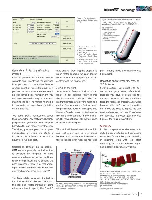
Figure 1. The transform part<br />
zero software feature was<br />
designed to minimize steps.<br />
Figure 2. Workpiece surface contact point + tool vector<br />
EXAMPLE: G01 X10.Y10.Z10. I0.5J0.5K0.707106<br />
would be equivalent to: G01 X10.Y10.Z10.B45.C45<br />
Benefits of Tool<br />
Vector Input feature:<br />
• Program is machine<br />
independent<br />
• Control software computes<br />
machine angles and<br />
positions<br />
• Simplifi es post-processor<br />
1.<br />
2.<br />
3.<br />
4.<br />
Create a Rotary Position<br />
data block<br />
Set the Transform Part<br />
Zero fi eld to YES<br />
Insert a Transform Plane<br />
Reference Point data<br />
block<br />
Specify the distance to<br />
shift the part zero relative<br />
to the original setup<br />
Redundancy in Posting a Five-Axis<br />
Program<br />
Each time you refi xture, you have to waste<br />
valuable time re-entering the distance<br />
from part zero to the center lines of<br />
rotation and then repost the program. If<br />
your control has a software feature such<br />
as tool center point management, you<br />
only have to post the program once and<br />
machine the part—no matter where it is<br />
in relation to the center lines of rotation<br />
on the machine.<br />
Tool center point management solves<br />
the problem for CAM software. The CAM<br />
programmer generates the toolpath<br />
based on the part model’s zero location.<br />
Therefore, you can post the program<br />
independent of where the stock is<br />
fi xtured on the table—a substantial time<br />
saver for a fi ve-axis part.<br />
Complex and Diffi cult Post Processors<br />
CAM systems generally use tool vectors<br />
to generate the toolpath. To make<br />
programs independent of the machine’s<br />
rotary confi guration and to simplify the<br />
post processor, there is a tool vector<br />
input control software feature for fi veaxis<br />
machining centers (see Figure 2).<br />
This feature lets you specify the tool tip<br />
location relative to the workpiece and<br />
the tool axis vector instead of using<br />
address letters to specify the B and C<br />
axes angles. Executing the program is<br />
much faster because the post doesn’t<br />
need the machine confi guration and the<br />
centerline of the rotary axes.<br />
Marks on the Part<br />
Simultaneous fi ve-axis toolpaths can<br />
result in odd looping rotary moves<br />
that leave marks on the part when the<br />
program is interpolated by the machine’s<br />
control. One solution is a feature called<br />
toolpath linearization, which is specifi c to<br />
fi ve-axis, G-code programs. It eliminates<br />
the many line segments in the form of<br />
XYZBC moves that a CAM system uses<br />
to create a smooth part.<br />
With toolpath linearization, the tool tip<br />
and tool vector can be interpolated<br />
between tool positions with respect to<br />
the workpiece even with the tool and<br />
Fig 3ab – with toolpath linearization, the tool tip and tool<br />
vector can be interpolated between tool positions with<br />
respect to the workpiece even with the tool and part<br />
rotating inside the machine<br />
part rotating inside the machine (see<br />
Figures 3ab).<br />
Reposting to Adjust for Tool Wear on<br />
3-D Surfaces<br />
For 3-D surfaces, you cut off of the tool<br />
centerline to get a better surface fi nish.<br />
Because you have to adjust the tool<br />
diameter for wear, you are sometimes<br />
forced to repost the program. A software<br />
feature called 3-D tool compensation<br />
eliminates the need to repost the part<br />
program because the control’s software<br />
compensates for the tool geometry (see<br />
Figure 4 for visual explanation).<br />
Summary<br />
In this competitive environment with<br />
skilled labor shortages and demanding<br />
schedules for complex parts, investing<br />
in machine tools with the latest<br />
technology is the most effi cient way to<br />
see measurable productivity gains.<br />
Figure 4. Workpiece surface contact point + contact point<br />
surface normal + tool vector<br />
EXAMPLE: M128 3D Tool Geometry Compensation<br />
G41.2D_ R_G00 X0.Y0.Z0. U0.V0.W1. I0.J0.K1.<br />
G01 X10.Y10.Z10. U0.V0.W1. I0.5J0.5K0.707106 F1000<br />
XYZ = Surface contact point<br />
UVW = Surface normal at contact point<br />
IJK = Tool vector<br />
3-D tool geometry compensation.<br />
indometalworking news Vol. 2 / 2008 27