Low Cost, Dual-Channel, 15V Pin Electronics Driver ... - Semtech
Low Cost, Dual-Channel, 15V Pin Electronics Driver ... - Semtech
Low Cost, Dual-Channel, 15V Pin Electronics Driver ... - Semtech

Create successful ePaper yourself
Turn your PDF publications into a flip-book with our unique Google optimized e-Paper software.
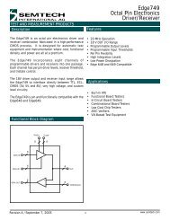
E7802<br />
TEST AND MEASUREMENT PRODUCTS<br />
AC Characteristics (continued)<br />
Parameter Symbol Min Typ Max Units<br />
Comparator (Note 2)<br />
Comparator Propagation Delay (Figure 10, Note 5) Tpd +/- 3.5 5 6.5 ns<br />
Propagation Delay Matching (Note 5) |(Tpd+) - (Tpd-)| 0.5 1.5 ns<br />
Propagation Delay Tempco (∆Tj = 25°C to 100°C) ∆Tpd/∆T 15 20 ps/°C<br />
Propagation Delay Dispersion vs. Overdrive (Note 7) (Figure 11) ∆Tpd/∆(VINP-<br />
VCH(L))<br />
100mV to 1V Overdrive 2.5 3.5 ns<br />
1V to 2.5V Overdrive 0.25 0.5 ns<br />
Propagation Delay Dispersion vs. Common Mode (Figure 12, Notes 3, 7) ∆Tpd(cm) 0.5 ns<br />
Comparator Bandwidth (Note 4) Fmax 100 MHz<br />
Minimum Pulse Width 5 ns<br />
VINP Capacitance CVINP 3 pF<br />
Note 1: <strong>Driver</strong> AC specifications are with Tj = 65 o C ± 3 o C, VCC = <strong>15V</strong>, VDD = 3.3V, DVEE = 0V, VEE = -5V,<br />
VL = 0, VH = 3.0, into 20 inches of 50Ω transmission line unless otherwise noted.<br />
Note 2: Tj = 65 o C ± 3 o C, CVH = 1.5, CVL = 1.5, VINP 0 - 3V @ 10MHz. VCC = <strong>15V</strong>, VDD = 3.3V, DVEE = 0V,<br />
VEE = -5V unless otherwise noted.<br />
Note 3: V VINP = 5V pp, 0.5V < V CVH/L < 1.5V.<br />
Note 4: Comparator bandwidth is the maximum frequency under which the comparator will switch with<br />
CVH/CVL = 1.5V, VINP = 0 to 3V.<br />
Note 5: V VINP = 5Vpp, VCVH,L = 2.5V.<br />
Note 6: Measured with 33pF at end of transmission line. See “Optimizing <strong>Driver</strong> Waveforms” Section for<br />
characteristics with different capacitive loads.<br />
Note 7: CVH, CVL are Calibrated Threshold Values (i.e., “Switching Point”).<br />
Note 8: VCC = 9V, DVEE = 0V, VEE = -5V.<br />
Test Circuits:<br />
Measurement Point (VX)<br />
DOUT<br />
45.3Ω<br />
Measurement Point (VX)<br />
DOUT<br />
VINP<br />
C LOAD<br />
953Ω<br />
Oscilloscope<br />
50 Ω<br />
VINP<br />
18nH<br />
20" T-line<br />
50 Ω<br />
Oscilloscope<br />
50 Ω<br />
Figure 5a. <strong>Driver</strong> Output/Comparator Input, Lumped Load<br />
Figure 5b. <strong>Driver</strong> Output/Comparator Input, 50Ω Load<br />
DOUT<br />
45.3Ω<br />
Measurement Point (VX)<br />
VINP<br />
18nH<br />
20" T-line<br />
50 Ω<br />
953Ω<br />
Oscilloscope<br />
50 Ω<br />
Figure 5c. <strong>Driver</strong> Output/Comparator Input, 1KΩ Load<br />
© 2008 <strong>Semtech</strong> Corp. , Rev. 5, 3/7/08<br />
18<br />
www.semtech.com