front page - tuprints - Technische Universität Darmstadt
front page - tuprints - Technische Universität Darmstadt
front page - tuprints - Technische Universität Darmstadt

You also want an ePaper? Increase the reach of your titles
YUMPU automatically turns print PDFs into web optimized ePapers that Google loves.
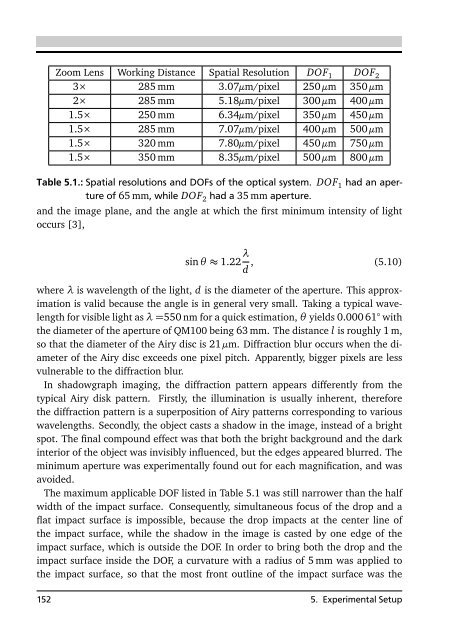
Zoom Lens Working Distance Spatial Resolution DOF 1 DOF 2<br />
3× 285 mm 3.07µm/pixel 250 µm 350 µm<br />
2× 285 mm 5.18µm/pixel 300 µm 400 µm<br />
1.5× 250 mm 6.34µm/pixel 350 µm 450 µm<br />
1.5× 285 mm 7.07µm/pixel 400 µm 500 µm<br />
1.5× 320 mm 7.80µm/pixel 450 µm 750 µm<br />
1.5× 350 mm 8.35µm/pixel 500 µm 800 µm<br />
Table 5.1.: Spatial resolutions and DOFs of the optical system. DOF 1 had an aperture<br />
of 65 mm, while DOF 2 had a 35 mm aperture.<br />
and the image plane, and the angle at which the first minimum intensity of light<br />
occurs [3],<br />
sin θ ≈ 1.22 λ d , (5.10)<br />
where λ is wavelength of the light, d is the diameter of the aperture. This approximation<br />
is valid because the angle is in general very small. Taking a typical wavelength<br />
for visible light as λ =550 nm for a quick estimation, θ yields 0.000 61° with<br />
the diameter of the aperture of QM100 being 63 mm. The distance l is roughly 1 m,<br />
so that the diameter of the Airy disc is 21 µm. Diffraction blur occurs when the diameter<br />
of the Airy disc exceeds one pixel pitch. Apparently, bigger pixels are less<br />
vulnerable to the diffraction blur.<br />
In shadowgraph imaging, the diffraction pattern appears differently from the<br />
typical Airy disk pattern. Firstly, the illumination is usually inherent, therefore<br />
the diffraction pattern is a superposition of Airy patterns corresponding to various<br />
wavelengths. Secondly, the object casts a shadow in the image, instead of a bright<br />
spot. The final compound effect was that both the bright background and the dark<br />
interior of the object was invisibly influenced, but the edges appeared blurred. The<br />
minimum aperture was experimentally found out for each magnification, and was<br />
avoided.<br />
The maximum applicable DOF listed in Table 5.1 was still narrower than the half<br />
width of the impact surface. Consequently, simultaneous focus of the drop and a<br />
flat impact surface is impossible, because the drop impacts at the center line of<br />
the impact surface, while the shadow in the image is casted by one edge of the<br />
impact surface, which is outside the DOF. In order to bring both the drop and the<br />
impact surface inside the DOF, a curvature with a radius of 5 mm was applied to<br />
the impact surface, so that the most <strong>front</strong> outline of the impact surface was the<br />
152 5. Experimental Setup