- Page 1 and 2:
Drop Impact on Dry Surfaces with Ph
- Page 3 and 4:
Hiermit versichere ich, die vorlieg
- Page 5 and 6:
Fachgebiet Reaktive Strömungslehre
- Page 7 and 8:
to non-monotonic threshold impact v
- Page 9 and 10:
Splash, einseitiger Splash sowie de
- Page 11 and 12:
3.4.2. Calibration of the Infrared
- Page 14 and 15:
Nomenclature Latin capitals Unit A
- Page 16 and 17:
k angular wavenumber rad m −1 k R
- Page 18 and 19:
F G ge i K L lam m max min n opt r
- Page 20 and 21:
1 Introduction 1.1 Motivation Aircr
- Page 22 and 23:
of the WCE acquired experimentally
- Page 24:
passage was cooled down to −196
- Page 27 and 28:
SLD icing conditions have been defi
- Page 29 and 30:
−9 ◦ C and layers of freezing r
- Page 31 and 32:
adjacent downstream control volume,
- Page 33 and 34:
conventional methods. Papadakis et
- Page 35 and 36:
Figure 2.5.: Ice horn and clear ice
- Page 37 and 38:
This model showed good agreement un
- Page 39 and 40: Xu et al. proposed the following sc
- Page 41 and 42: Figure 2.9.: Splash thresholds of t
- Page 43 and 44: Chen and Wang [28] observed the dro
- Page 45 and 46: 2.14 shows. On stainless steel, tin
- Page 47 and 48: years ago [157]. Another peculiarit
- Page 49 and 50: Figure 2.17.: At an ambient pressur
- Page 51 and 52: The temperature needs to be found o
- Page 53 and 54: The Stefan number St S completely c
- Page 55 and 56: T(x, 0) = T A < T m , 0 < x < ∞ b
- Page 57 and 58: Figure 2.20: Fraction of solidifica
- Page 59 and 60: The mathematical description of the
- Page 61 and 62: asal plane. Without all these facto
- Page 64: Part I. Impact of Supercooled Water
- Page 68 and 69: 3 Experimental Setup This chapter i
- Page 70 and 71: drop and the tube as between such t
- Page 72 and 73: of nucleation ice dendrite growth,
- Page 74 and 75: The boundary condition is then 1
- Page 76 and 77: 0.021 W m −1 K −1 at −165 ◦
- Page 78 and 79: outlet of the liquid. There are two
- Page 80 and 81: The maximum depth of water in the c
- Page 82 and 83: Figure 3.11.: Pneumatic drop genera
- Page 84 and 85: Figure 3.13.: Pneumatic drop genera
- Page 86 and 87: Adjusting the Pulse Width Longer el
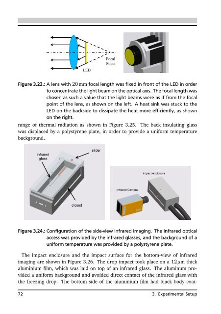
- Page 88 and 89: (a) Shadowgraph imaging (b) The sid
- Page 92 and 93: Figure 3.25.: The transmittance of
- Page 94 and 95: eproducible. The SHS was created by
- Page 96 and 97: Figure 3.30.: Planck’s law The ot
- Page 98 and 99: Figure 3.32.: Heterogeneity of the
- Page 100 and 101: Figure 3.35.: The valid region afte
- Page 102 and 103: Divided by dΩ, Eq. 3.33 is related
- Page 104 and 105: Figure 3.39.: The wavelength depend
- Page 106 and 107: Figure 3.41.: Orientation dependenc
- Page 108 and 109: wavelength, so that the value for r
- Page 110 and 111: Temperature Gradient In light of th
- Page 112 and 113: (a) 0.00 ms (b) 1.39 ms (c) 2.79 ms
- Page 114 and 115: Figure 3.48.: Synchronization syste
- Page 116: Figure 3.50.: Experimental setup fo
- Page 119 and 120: (a) 0 ms (b) 0 ms (c) 0.6 ms (d) 0.
- Page 121 and 122: Figure 4.2.: The dynamic spreading
- Page 123 and 124: Figure 4.4.: Influence envelope of
- Page 125 and 126: (a) 0 ms (b) 0.4 ms (c) 0.8 ms (d)
- Page 127 and 128: (a) 0 ms (b) 1.39 ms (c) 2.79 ms (d
- Page 129 and 130: (a) 0 ms (b) 0.05 ms (c) 0.1 ms (d)
- Page 131 and 132: (a) −4 ◦ C, at 6.8 ms. (b) −1
- Page 133 and 134: The contact temperature is closer t
- Page 135 and 136: Obviously, the contact temperature
- Page 137 and 138: Figure 4.13.: The dimensionless min
- Page 139 and 140: always after the receding reached t
- Page 142:
Part II reports the experimental in
- Page 145 and 146:
to realize a high-speed rotation of
- Page 147 and 148:
Figure 5.2.: Impact surface with di
- Page 149 and 150:
Various such devices were developed
- Page 151 and 152:
than the values reported in literat
- Page 153 and 154:
Figure 5.7.: The monodisperse drop
- Page 155 and 156:
This performance is a reminiscence
- Page 157 and 158:
Figure 5.11.: The merging distance
- Page 159 and 160:
signal and the excitation signal of
- Page 161 and 162:
The analogy with a capacitor led to
- Page 163 and 164:
The real situation in the applicati
- Page 165 and 166:
Figure 5.15.: Static electric field
- Page 167 and 168:
Figure 5.19.: Phase shift and pulse
- Page 169 and 170:
disadvantage is that the number of
- Page 171 and 172:
Zoom Lens Working Distance Spatial
- Page 173 and 174:
the impact surface was not a sharp
- Page 175 and 176:
5.5 Synchronization Both single pul
- Page 177 and 178:
The last note on these two pulse tr
- Page 179 and 180:
Figure 5.28.: Calculation of the im
- Page 182 and 183:
6 Results and Discussion This chapt
- Page 184 and 185:
(a) 0 µs (b) 2 µs (c) 4 µs (d) 6
- Page 186 and 187:
high impact velocities approaching
- Page 188 and 189:
(a) 32 µs (b) 84 µs (c) 100 µs F
- Page 190 and 191:
(a) (b) (c) Figure 6.8.: Examinatio
- Page 192 and 193:
Our observations show that the lame
- Page 194 and 195:
6.3 Velocity of the Uprising Jet In
- Page 196 and 197:
(a) 1 µs (b) 3 µs (c) 4 µs Figur
- Page 198 and 199:
(a) 0 µs (b) 8 µs (c) 32 µs Figu
- Page 200 and 201:
(a) 45° target (b) 75° target (c)
- Page 202 and 203:
Nevertheless, the drop volume was e
- Page 204:
was surface tension. These factors
- Page 207 and 208:
the motion of the impinging water,
- Page 209 and 210:
of the single-side splash, the latt
- Page 211 and 212:
(a) 0 µs (b) 2 µs (c) 4 µs (d) 6
- Page 213 and 214:
(a) 0 µs (b) 1 µs (c) 2 µs (d) 3
- Page 215 and 216:
(a) 0 µs (b) 3 µs (c) 6 µs (d) 9
- Page 217 and 218:
(a) 0 µs (b) 10 µs (c) 11 µs (d)
- Page 219 and 220:
(a) 0 µs (b) 3 µs (c) 5 µs (d) 8
- Page 221 and 222:
(a) 0 µs (b) 1 µs (c) 2 µs (d) 3
- Page 223 and 224:
(a) 0 µs (b) 6 µs (c) 10 µs (d)
- Page 225 and 226:
(a) 0 µs (b) 1 µs (c) 3 µs (d) 5
- Page 227 and 228:
(a) 0 µs (b) 8 µs (c) 24 µs (d)
- Page 229 and 230:
(a) 0 µs (b) 2 µs (c) 5 µs (d) 8
- Page 231 and 232:
(a) 0 µs (b) 16 µs (c) 32 µs (d)
- Page 233 and 234:
(a) 0 µs (b) 8 µs (c) 20 µs (d)
- Page 235 and 236:
A.7 5° target (a) 0 µs (b) 24 µs
- Page 237 and 238:
(a) 0 µs (b) 20 µs (c) 36 µs (d)
- Page 239 and 240:
(a) 0 µs (b) 8 µs (c) 16 µs (d)
- Page 241 and 242:
(a) 0 µs (b) 24 µs (c) 52 µs (d)
- Page 243 and 244:
(a) 0 µs (b) 16 µs (c) 32 µs (d)
- Page 245 and 246:
(a) 0 µs (b) 20 µs (c) 40 µs (d)
- Page 247 and 248:
(a) 0 µs (b) 10 µs (c) 22 µs (d)
- Page 249 and 250:
(a) 0 µs (b) 36 µs (c) 68 µs (d)
- Page 251 and 252:
(a) 0 µs (b) 36 µs (c) 72 µs (d)
- Page 253 and 254:
(a) 0 µs (b) 8 µs (c) 16 µs (d)
- Page 255 and 256:
(a) (b) (c) (d) (e) (f) Figure B.4.
- Page 257 and 258:
(a) 0 ms (b) 0.4 ms (c) 0.5 ms (d)
- Page 259 and 260:
(a) 0 ms (b) 0.35 ms (c) 1 ms (d) 1
- Page 261 and 262:
2.15.Prompt splash (left) was docum
- Page 263 and 264:
3.12.Time t =0 corresponds to the s
- Page 265 and 266:
3.31.The extension ring (left) betw
- Page 267 and 268:
4.7. Infrared imaging: total reboun
- Page 269 and 270:
5.5. The custom made vibrating orif
- Page 271 and 272:
5.14.Static electric field between
- Page 273 and 274:
6.6. Capillary wave created by the
- Page 275 and 276:
A.5. Drop diameter: 189 µm, impact
- Page 277 and 278:
A.29.Drop diameter: 203 µm, impact
- Page 280:
List of Tables 2.1. MVD of Freezing
- Page 283 and 284:
Imaging and Computer Simulations. T
- Page 285 and 286:
[42] GENT, R. W., N. P. DART and J.
- Page 287 and 288:
[70] KOROLEV, ALEXEI V., GEORGE A.
- Page 289 and 290:
[99] MUNDO, CHR., M. SOMMERFELD and
- Page 291 and 292:
[125] RYERSON, CHARLES C., GEORGE G
- Page 293 and 294:
[153] ŠIKALO Š., C. TROPEA and E.
- Page 296:
Curriculum Vitae Personal Informati


