MICRO-STRUCTURE ANALYSIS OF PLANT TISSUES - Lublin
MICRO-STRUCTURE ANALYSIS OF PLANT TISSUES - Lublin
MICRO-STRUCTURE ANALYSIS OF PLANT TISSUES - Lublin

You also want an ePaper? Increase the reach of your titles
YUMPU automatically turns print PDFs into web optimized ePapers that Google loves.
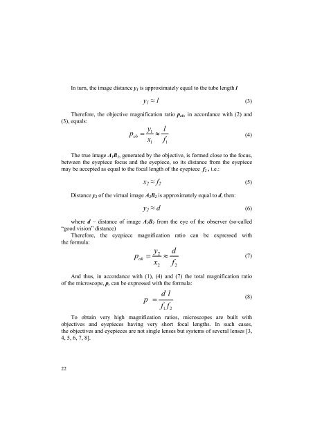
In turn, the image distance y 1 is approximately equal to the tube length l<br />
y 1 ≈ l (3)<br />
Therefore, the objective magnification ratio p ob , in accordance with (2) and<br />
(3), equals:<br />
p ob<br />
1<br />
The true image A 1 B 1 , generated by the objective, is formed close to the focus,<br />
between the eyepiece focus and the eyepiece, so its distance from the eyepiece<br />
may be accepted as equal to the focal length of the eyepiece f 2 , i.e.:<br />
(4)<br />
x 2 ≈ f 2 (5)<br />
Distance y 2 of the virtual image A 2 B 2 is approximately equal to d, then:<br />
y 2 ≈ d (6)<br />
where d – distance of image A 2 B 2 from the eye of the observer (so-called<br />
“good vision” distance)<br />
Therefore, the eyepiece magnification ratio can be expressed with<br />
the formula:<br />
p ok<br />
y1<br />
=<br />
x<br />
≈<br />
y<br />
=<br />
x<br />
And thus, in accordance with (1), (4) and (7) the total magnification ratio<br />
of the microscope, p, can be expressed with the formula:<br />
p =<br />
To obtain very high magnification ratios, microscopes are built with<br />
objectives and eyepieces having very short focal lengths. In such cases,<br />
the objectives and eyepieces are not single lenses but systems of several lenses [3,<br />
4, 5, 6, 7, 8].<br />
2<br />
2<br />
l<br />
f<br />
d<br />
1<br />
≈<br />
l<br />
f 1<br />
f 2<br />
d<br />
f<br />
2<br />
(7)<br />
(8)<br />
22