6U VME 6023 Crate Series
6U VME 6023 Crate Series
6U VME 6023 Crate Series

You also want an ePaper? Increase the reach of your titles
YUMPU automatically turns print PDFs into web optimized ePapers that Google loves.
NEMbox/NIMbox Programmable NIM Module<br />
NEMbox (Nuclear Electronics Miniature Box) is a programmable Logic / DAQ module, powered<br />
either in a NIM crate (NIMbox version) or with a commercial 6V output AC/DC transformer<br />
(NEMbox version). It is well suited for scientific and educational purposes.<br />
NEMbox and NIMbox consist of a FPGA main and carrier board and up to 4 I/O Submodules, VHDL<br />
modules as well as interface software featuring "LogicPool", a very new and unique way for the<br />
user to build up his specific setup by graphically wiring prebuilt functional modules, for example<br />
with Labview. A user defined wiring configuration can be saved on an EPROM chip so that the<br />
module does not need to be reprogrammed in case of power failure or system reset. All<br />
communication with the module as well as programming is done via a USB-2 interface.<br />
Programmable as coincidence, fan in / fan out, scaler, logic, discriminator, ADC, TDC, etc.,<br />
NEMbox/NIMbox finds many applications in trigger logic and data acquisition, and allows to cut<br />
costs because one single unit can replace the functionality of several non programmable NIM<br />
modules.<br />
Hardware<br />
<br />
<br />
Main FPGA board with USB, 100 MHz clock, 4 slots, EEPROM for saving user configurations<br />
4 submodules choosen by the customer<br />
Software<br />
Labview examples:<br />
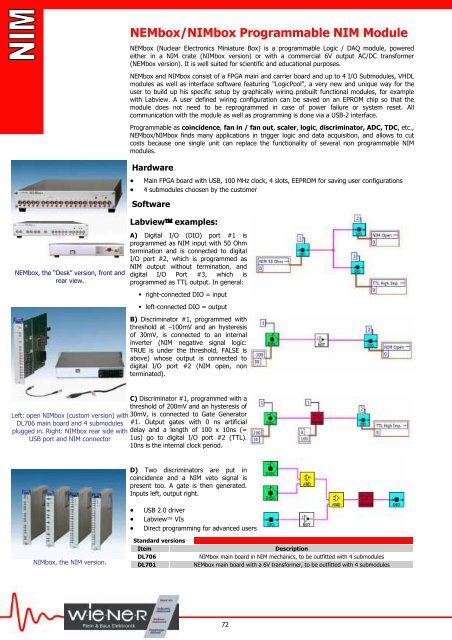
NEMbox, the “Desk” version, front and<br />
rear view.<br />
A) Digital I/O (DIO) port #1 is<br />
programmed as NIM input with 50 Ohm<br />
termination and is connected to digital<br />
I/O port #2, which is programmed as<br />
NIM output without termination, and<br />
digital I/O Port #3, which is<br />
programmed as TTL output. In general:<br />
right-connected DIO = input<br />
left-connected DIO = output<br />
B) Discriminator #1, programmed with<br />
threshold at –100mV and an hysteresis<br />
of 30mV, is connected to an internal<br />
inverter (NIM negative signal logic:<br />
TRUE is under the threshold, FALSE is<br />
above) whose output is connected to<br />
digital I/O port #2 (NIM open, non<br />
terminated).<br />
C) Discriminator #1, programmed with a<br />
threshold of 200mV and an hysteresis of<br />
Left: open NIMbox (custom version) with 30mV, is connected to Gate Generator<br />
DL706 main board and 4 submodules #1. Output gates with 0 ns artificial<br />
plugged in. Right: NIMbox rear side with delay and a length of 100 x 10ns (=<br />
USB port and NIM connector 1us) go to digital I/O port #2 (TTL).<br />
10ns is the internal clock period.<br />
D) Two discriminators are put in<br />
coincidence and a NIM veto signal is<br />
present too. A gate is then generated.<br />
Inputs left, output right.<br />
<br />
<br />
<br />
USB 2.0 driver<br />
Labview VIs<br />
Direct programming for advanced users<br />
NIMbox, the NIM version.<br />
Standard versions<br />
Item<br />
DL706<br />
DL701<br />
Description<br />
NIMbox main board in NIM mechanics, to be outfitted with 4 submodules<br />
NEMbox main board with a 6V transformer, to be outfitted with 4 submodules<br />
72