User manual (PDF) - JAI Pulnix
User manual (PDF) - JAI Pulnix
User manual (PDF) - JAI Pulnix

Create successful ePaper yourself
Turn your PDF publications into a flip-book with our unique Google optimized e-Paper software.
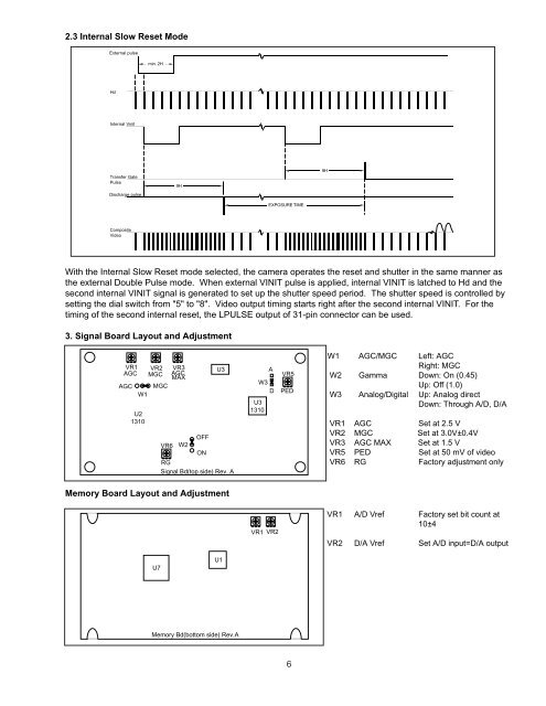
2.3 Internal Slow Reset Mode<br />
External pulse<br />
min. 2H<br />
Hd<br />
Internal Vinit<br />
Transfer Gate<br />
Pulse<br />
Discharge pulse<br />
9H<br />
9H<br />
EXPOSURE TIME<br />
Composite<br />
Video<br />
With the Internal Slow Reset mode selected, the camera operates the reset and shutter in the same manner as<br />
the external Double Pulse mode. When external VINIT pulse is applied, internal VINIT is latched to Hd and the<br />
second internal VINIT signal is generated to set up the shutter speed period. The shutter speed is controlled by<br />
setting the dial switch from "5" to "8". Video output timing starts right after the second internal VINIT. For the<br />
timing of the second internal reset, the LPULSE output of 31-pin connector can be used.<br />
3. Signal Board Layout and Adjustment<br />
VR1 VR2 VR3<br />
AGC MGC AGC<br />
MAX<br />
AGC MGC<br />
W1<br />
U2<br />
1310<br />
U3<br />
OFF<br />
VR6 W2<br />
ON<br />
RG<br />
Signal Bd(top side) Rev. A<br />
A<br />
W3<br />
D<br />
U3<br />
1310<br />
VR5<br />
PED<br />
W1 AGC/MGC Left: AGC<br />
Right: MGC<br />
W2 Gamma Down: On (0.45)<br />
Up: Off (1.0)<br />
W3 Analog/Digital Up: Analog direct<br />
Down: Through A/D, D/A<br />
VR1 AGC Set at 2.5 V<br />
VR2 MGC Set at 3.0V±0.4V<br />
VR3 AGC MAX Set at 1.5 V<br />
VR5 PED Set at 50 mV of video<br />
VR6 RG Factory adjustment only<br />
Memory Board Layout and Adjustment<br />
VR1 VR2<br />
VR1 A/D Vref Factory set bit count at<br />
10±4<br />
VR2 D/A Vref Set A/D input=D/A output<br />
U7<br />
U1<br />
Memory Bd(bottom side) Rev.A<br />
6