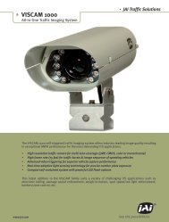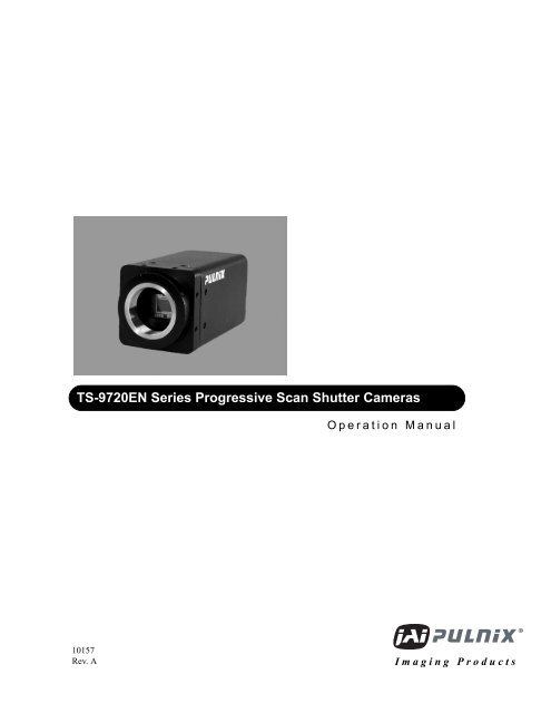
TS-9720EN Series Progressive Scan Shutter Cameras - JAI Pulnix
TS-9720EN Series Progressive Scan Shutter Cameras - JAI Pulnix
TS-9720EN Series Progressive Scan Shutter Cameras - JAI Pulnix

Create successful ePaper yourself
Turn your PDF publications into a flip-book with our unique Google optimized e-Paper software.
<strong>TS</strong>-<strong>9720EN</strong> <strong>Series</strong> <strong>Progressive</strong> <strong>Scan</strong> <strong>Shutter</strong> <strong>Cameras</strong><br />
Operation Manual<br />
10157<br />
Rev. A<br />
Imaging Products
Notice<br />
i<br />
Notice Page<br />
The material contained in this manual consists of information that is proprietary to <strong>JAI</strong> PULNiX, Inc., and may only be used<br />
by the purchasers of the product. <strong>JAI</strong> PULNiX, Inc. makes no warranty for the use of its product and assumes no responsibility<br />
for any errors which may appear or for damages resulting from the use of the information contained herein. <strong>JAI</strong> PULNiX, Inc.<br />
reserves the right to make changes without notice.<br />
Microsoft, Windows 95, 98, NT, 2000, XP, and Windows Explorer are either registered trademarks or trademarks of<br />
Microsoft Corporation in the United States and/or other countries.<br />
Warranty<br />
Please contact your factory representative for details about the warranty.<br />
Certifications<br />
CE Compliance<br />
The <strong>TS</strong>-<strong>9720EN</strong> series of cameras has been certified to conform to the requirements of Council Directive 89/336/EC for electromagnetic<br />
compatibility and to comply with the following European Standards:<br />
EMC EN55022A: 1998 + A1: 2000 + A2: 2003;<br />
EN55024: 1998 + A1: 2001 + A2: 2003<br />
All <strong>JAI</strong> PULNiX products bearing the CE mark have been declared to be in conformance with the applicable EEC Council<br />
Directives. However, certain factory-installed options or customer-requested modifications may compromise electromagnetic<br />
compatibility and affect CE compliance. Please note that the use of interconnect cables that are not properly grounded and<br />
shielded may affect CE compliance.<br />
Contact the <strong>JAI</strong> PULNiX Applications Engineering Department for further information regarding CE compliance.<br />
FCC<br />
This equipment has been tested and found to comply with the limits for a Class A digital device, pursuant to Part 15 of the<br />
FCC Rules. These limits are designed to provide reasonable protection against harmful interference when the equipment is<br />
operated in a commercial environment. This equipment generates, uses and can radiate radio frequency energy and, if not<br />
installed and used in accordance with the instruction manual, may cause harmful interference to radio communications. Operation<br />
of this equipment in a residential area may cause harmful interference, in which case the user will be required to correct<br />
the interference at his own expense.<br />
WARNING<br />
Changes or modifications to this unit not expressly approved by the party responsible for<br />
FCC compliance could void the user’s authority to operate the equipment.<br />
<strong>TS</strong>-<strong>9720EN</strong> <strong>Series</strong> Operation Manual<br />
<strong>JAI</strong> PULNiX, Inc.<br />
625 River Oaks Parkway<br />
San Jose, CA 95134<br />
Tel:(408) 383-0300<br />
Tel:(800) 445-5444<br />
Fax:(408) 383-0301<br />
E-mail: imaging@jaipulnix.com<br />
www.jaipulnix.com<br />
AUTOMATED<br />
IMAGING<br />
MEMBER<br />
FILE #<br />
A3942<br />
U L<br />
FIR M<br />
®<br />
R E GISTE R E D<br />
ISO-9001<br />
ASSOCIATION<br />
<strong>JAI</strong> PULNiX, INC.<br />
<strong>TS</strong>-<strong>9720EN</strong> <strong>Series</strong> <strong>Progressive</strong> <strong>Scan</strong> <strong>Shutter</strong> Camera
Page ii<br />
Table of Contents<br />
1 Introduction . . . . . . . . . . . . . . . . . . . . . . . . . . . . . . . . . . . . . . .1<br />
1.1 Scope of this Manual . . . . . . . . . . . . . . . . . . . . . . . . . . . . . . . . . . 1<br />
1.2 Related Documents . . . . . . . . . . . . . . . . . . . . . . . . . . . . . . . . . . . 1<br />
1.3 Key Functions of the <strong>TS</strong>-<strong>9720EN</strong> Camera . . . . . . . . . . . . . . . . . . 1<br />
1.4 Product Description . . . . . . . . . . . . . . . . . . . . . . . . . . . . . . . . . . . 2<br />
2 Getting Started. . . . . . . . . . . . . . . . . . . . . . . . . . . . . . . . . . . . .3<br />
2.1 Required Equipment. . . . . . . . . . . . . . . . . . . . . . . . . . . . . . . . . . . 3<br />
2.2 Network Settings . . . . . . . . . . . . . . . . . . . . . . . . . . . . . . . . . . . . . 3<br />
2.2.1 Default Network Settings for the <strong>TS</strong>-<strong>9720EN</strong> Camera . . . . . . . . . . . . . 3<br />
2.2.2 Changing the IP Address of the <strong>TS</strong>-<strong>9720EN</strong> Camera. . . . . . . . . . . . . . 4<br />
2.3 Installing the Required Software. . . . . . . . . . . . . . . . . . . . . . . . . . 4<br />
3 Tutorial. . . . . . . . . . . . . . . . . . . . . . . . . . . . . . . . . . . . . . . . . . .6<br />
3.1 Image Capturing . . . . . . . . . . . . . . . . . . . . . . . . . . . . . . . . . . . . . . 6<br />
3.1.1 Start Up the EN Setup Software . . . . . . . . . . . . . . . . . . . . . . . . . . . . . . 6<br />
3.1.2 Camera Properties . . . . . . . . . . . . . . . . . . . . . . . . . . . . . . . . . . . . . . . . 7<br />
3.1.3 Live Image Capturing/Focusing. . . . . . . . . . . . . . . . . . . . . . . . . . . . . . . 8<br />
3.1.4 Image Properties . . . . . . . . . . . . . . . . . . . . . . . . . . . . . . . . . . . . . . . . . 14<br />
3.2 Image Transfer . . . . . . . . . . . . . . . . . . . . . . . . . . . . . . . . . . . . . . 15<br />
3.2.1 FTP Image Transfer . . . . . . . . . . . . . . . . . . . . . . . . . . . . . . . . . . . . . . 15<br />
3.3 ADR (Automatic Dynamic Range) Control . . . . . . . . . . . . . . . . . 16<br />
3.3.1 Light Sensor Connection . . . . . . . . . . . . . . . . . . . . . . . . . . . . . . . . . . . 16<br />
3.3.2 Flash Nighttime Light Control . . . . . . . . . . . . . . . . . . . . . . . . . . . . . . . 17<br />
3.4 Time Synchronization . . . . . . . . . . . . . . . . . . . . . . . . . . . . . . . . . 19<br />
3.5 Static IP Address Assignment. . . . . . . . . . . . . . . . . . . . . . . . . . . 20<br />
3.5.1 DHCP Client . . . . . . . . . . . . . . . . . . . . . . . . . . . . . . . . . . . . . . . . . . . . 20<br />
3.6 Maintenance . . . . . . . . . . . . . . . . . . . . . . . . . . . . . . . . . . . . . . . . 22<br />
3.6.1 Debug Counters . . . . . . . . . . . . . . . . . . . . . . . . . . . . . . . . . . . . . . . . . 22<br />
3.6.2 Firmware Upgrade. . . . . . . . . . . . . . . . . . . . . . . . . . . . . . . . . . . . . . . . 23<br />
3.6.3 RS-232 PowerPC Debug Port. . . . . . . . . . . . . . . . . . . . . . . . . . . . . . . 24<br />
4 Uploading the Firmware . . . . . . . . . . . . . . . . . . . . . . . . . . . . 29<br />
4.1 To Verify Version Numbers for all Firmware . . . . . . . . . . . . . . . . 29<br />
4.1.1 RS-232 PPC Debug Serial Port/Telnet . . . . . . . . . . . . . . . . . . . . . . . . 29<br />
4.1.2 EN Setup Software . . . . . . . . . . . . . . . . . . . . . . . . . . . . . . . . . . . . . . . 29<br />
4.2 Updating the EN Application Software . . . . . . . . . . . . . . . . . . . . 29<br />
4.3 Updating the FPGA Bitfile. . . . . . . . . . . . . . . . . . . . . . . . . . . . . . 30<br />
4.4 Updating the Lib/Drv File . . . . . . . . . . . . . . . . . . . . . . . . . . . . . . 30<br />
4.5 Updating the OS Image . . . . . . . . . . . . . . . . . . . . . . . . . . . . . . . 30<br />
4.6 Updating the Camera’s H8 Firmware . . . . . . . . . . . . . . . . . . . . . 30<br />
4.7 Updating the Firmware Manually When the Network is Down . . 31<br />
5 Connectors and Cables . . . . . . . . . . . . . . . . . . . . . . . . . . . . . 32<br />
5.1 Connector Pin Configurations. . . . . . . . . . . . . . . . . . . . . . . . . . . 32<br />
5.1.1 12-Pin Connector . . . . . . . . . . . . . . . . . . . . . . . . . . . . . . . . . . . . . . . . 32<br />
5.1.2 High-Density 26-Pin D-Sub Connector . . . . . . . . . . . . . . . . . . . . . . . . 32<br />
5.1.3 10/100 BaseT Ethernet . . . . . . . . . . . . . . . . . . . . . . . . . . . . . . . . . . . . 33<br />
5.2 RS-232 Communication Cable . . . . . . . . . . . . . . . . . . . . . . . . . . 33<br />
5.3 Power Supplies and Power Cable Setup . . . . . . . . . . . . . . . . . . 34<br />
5.3.1 Power Supplies . . . . . . . . . . . . . . . . . . . . . . . . . . . . . . . . . . . . . . . . . . 34<br />
5.3.2 <strong>JAI</strong> PULNiX Power Cables . . . . . . . . . . . . . . . . . . . . . . . . . . . . . . . . . 34<br />
5.3.3 Building Your Own Power Cable . . . . . . . . . . . . . . . . . . . . . . . . . . . . . 35<br />
5.3.4 Attaching the Power Cable to the Connector . . . . . . . . . . . . . . . . . . . 35<br />
<strong>TS</strong>-<strong>9720EN</strong> <strong>Series</strong> <strong>Progressive</strong> <strong>Scan</strong> <strong>Shutter</strong> <strong>Cameras</strong>
Page iii<br />
Table of Contents<br />
5.4 Attaching the Camera Lens . . . . . . . . . . . . . . . . . . . . . . . . . . . . .35<br />
6 Camera Features . . . . . . . . . . . . . . . . . . . . . . . . . . . . . . . . . 36<br />
6.1 <strong>Progressive</strong> scanning . . . . . . . . . . . . . . . . . . . . . . . . . . . . . . . . . .36<br />
6.2 Asynchronous Reset . . . . . . . . . . . . . . . . . . . . . . . . . . . . . . . . . .36<br />
6.3 ADR (Automatic Dynamic Range) Control . . . . . . . . . . . . . . . . . .38<br />
6.3.1 Electronic <strong>Shutter</strong> . . . . . . . . . . . . . . . . . . . . . . . . . . . . . . . . . . . . . . . . 38<br />
6.3.2 Video Amplifier Gain Control. . . . . . . . . . . . . . . . . . . . . . . . . . . . . . . . 39<br />
6.3.3 A/D Converter Parameter (Vtop and Vbottom) . . . . . . . . . . . . . . . . . . 40<br />
6.4 Flash/Nighttime Light Control . . . . . . . . . . . . . . . . . . . . . . . . . . . .40<br />
6.5 External Control . . . . . . . . . . . . . . . . . . . . . . . . . . . . . . . . . . . . . .41<br />
6.5.1 RS-485 . . . . . . . . . . . . . . . . . . . . . . . . . . . . . . . . . . . . . . . . . . . . . . . . 41<br />
6.5.2 Ethernet. . . . . . . . . . . . . . . . . . . . . . . . . . . . . . . . . . . . . . . . . . . . . . . . 41<br />
6.6 Color Filter Array (Color Version) . . . . . . . . . . . . . . . . . . . . . . . . .41<br />
6.7 Image Formats . . . . . . . . . . . . . . . . . . . . . . . . . . . . . . . . . . . . . . .42<br />
6.7.1 TIF Format . . . . . . . . . . . . . . . . . . . . . . . . . . . . . . . . . . . . . . . . . . . . . 42<br />
6.7.2 JPEG Format . . . . . . . . . . . . . . . . . . . . . . . . . . . . . . . . . . . . . . . . . . . 42<br />
6.8 Image Transfer . . . . . . . . . . . . . . . . . . . . . . . . . . . . . . . . . . . . . . .43<br />
6.8.1 UDP Image Transfer on Setup Channel . . . . . . . . . . . . . . . . . . . . . . . 43<br />
6.8.2 TCP Message-Based Image Transfer on the Control Channel. . . . . . 43<br />
6.9 Image Buffering . . . . . . . . . . . . . . . . . . . . . . . . . . . . . . . . . . . . . .44<br />
6.10 FTP. . . . . . . . . . . . . . . . . . . . . . . . . . . . . . . . . . . . . . . . . . . . . . . .45<br />
6.11 NTP (Network Time Protocol). . . . . . . . . . . . . . . . . . . . . . . . . . . .45<br />
7 Troubleshooting. . . . . . . . . . . . . . . . . . . . . . . . . . . . . . . . . . . 47<br />
7.1 Problem 1: EN Setup Software Does Not Find Any<br />
Camera in the Network . . . . . . . . . . . . . . . . . . . . . . . . . . . . . .47<br />
7.2 Problem 2: EN Setup Software Found the Camera,<br />
But the Video Image is Too Dark or Just Black . . . . . . . . . . . .47<br />
7.3 Problem 3: TTL Trigger/Ethernet Trigger/Serial<br />
RS-485 Trigger Does not Generate Trigger . . . . . . . . . . . . . . .47<br />
7.4 Problem 4: JPEG Image is Either Corrupt or Not<br />
a Full-Size Image . . . . . . . . . . . . . . . . . . . . . . . . . . . . . . . . . . .48<br />
7.5 Problem 5: EN Camera Does Not Send any FTP<br />
Image to the FTP Server . . . . . . . . . . . . . . . . . . . . . . . . . . . . .48<br />
7.6 Problem 6: EN Camera Does Not Connect to Light<br />
Sensor or the Connection is Not Reliable . . . . . . . . . . . . . . . .48<br />
7.7 Problem 7: IO Board Communication Error . . . . . . . . . . . . . . . . .49<br />
7.8 Problem 8: Night Time Image is Too Bright and<br />
License Plate is Whited Out or Saturated . . . . . . . . . . . . . . . .50<br />
7.9 Problem 9: Timestamp is Not Set to Current Local Time . . . . . . .50<br />
7.10 Information and Support Resources. . . . . . . . . . . . . . . . . . . . . . .50<br />
8 Appendix . . . . . . . . . . . . . . . . . . . . . . . . . . . . . . . . . . . . . . . . 51<br />
8.1 Specifications . . . . . . . . . . . . . . . . . . . . . . . . . . . . . . . . . . . . . . . .51<br />
8.2 Physical Dimensions . . . . . . . . . . . . . . . . . . . . . . . . . . . . . . . . . .52<br />
8.3 Spectral Response . . . . . . . . . . . . . . . . . . . . . . . . . . . . . . . . . . . .52<br />
<strong>TS</strong>-<strong>9720EN</strong> <strong>Series</strong> <strong>Progressive</strong> <strong>Scan</strong> <strong>Shutter</strong> <strong>Cameras</strong>
Page iv<br />
List of Figures<br />
FIGURE 1. Typical Equipment Setup . . . . . . . . . . . . . . . . . . . . . . . . . . . . . . . . . . . . . . . . 3<br />
FIGURE 2. User Administration . . . . . . . . . . . . . . . . . . . . . . . . . . . . . . . . . . . . . . . . . . . . 6<br />
FIGURE 3. Properties . . . . . . . . . . . . . . . . . . . . . . . . . . . . . . . . . . . . . . . . . . . . . . . . . . . . 7<br />
FIGURE 4. Camera Properties . . . . . . . . . . . . . . . . . . . . . . . . . . . . . . . . . . . . . . . . . . . . . 8<br />
FIGURE 5. Live Image Capturing . . . . . . . . . . . . . . . . . . . . . . . . . . . . . . . . . . . . . . . . . . . 9<br />
FIGURE 6. Focus Bar . . . . . . . . . . . . . . . . . . . . . . . . . . . . . . . . . . . . . . . . . . . . . . . . . . 10<br />
FIGURE 7. Measuring Box Position . . . . . . . . . . . . . . . . . . . . . . . . . . . . . . . . . . . . . . . . 11<br />
FIGURE 8. Half Size Image Position . . . . . . . . . . . . . . . . . . . . . . . . . . . . . . . . . . . . . . . 12<br />
FIGURE 9. “Quad Size” Image Button . . . . . . . . . . . . . . . . . . . . . . . . . . . . . . . . . . . . . . 13<br />
FIGURE 10. Hardware Trigger Sniffing Mode. . . . . . . . . . . . . . . . . . . . . . . . . . . . . . . . . . 13<br />
FIGURE 11. 12-Pin Connector . . . . . . . . . . . . . . . . . . . . . . . . . . . . . . . . . . . . . . . . . . . . . 32<br />
FIGURE 12. 26-Pin HD-Sub Connector . . . . . . . . . . . . . . . . . . . . . . . . . . . . . . . . . . . . . . 32<br />
FIGURE 13.<br />
Serial Communication Cable RS-232B-12<br />
(<strong>JAI</strong> PULNiX part number: 310 132 19) . . . . . . . . . . . . . . . . . . . . . . . . . . . . 33<br />
FIGURE 14. 12P-02S Interface Cable (optional) . . . . . . . . . . . . . . . . . . . . . . . . . . . . . . . 35<br />
FIGURE 15. Timing Chart 1 . . . . . . . . . . . . . . . . . . . . . . . . . . . . . . . . . . . . . . . . . . . . . . . 37<br />
FIGURE 16. CFA Pattern . . . . . . . . . . . . . . . . . . . . . . . . . . . . . . . . . . . . . . . . . . . . . . . . . 41<br />
FIGURE 17. Enable TCP Image . . . . . . . . . . . . . . . . . . . . . . . . . . . . . . . . . . . . . . . . . . . . 44<br />
FIGURE 18. Physical Dimensions . . . . . . . . . . . . . . . . . . . . . . . . . . . . . . . . . . . . . . . . . . 52<br />
FIGURE 19. Spectral Response (B/W CCD for <strong>TS</strong>-<strong>9720EN</strong>) . . . . . . . . . . . . . . . . . . . . . 52<br />
FIGURE 20. Spectral Response (Color CCD for <strong>TS</strong>C-<strong>9720EN</strong> Only). . . . . . . . . . . . . . . . 53<br />
<strong>TS</strong>-<strong>9720EN</strong> <strong>Series</strong> <strong>Progressive</strong> <strong>Scan</strong> <strong>Shutter</strong> <strong>Cameras</strong>
Page v<br />
List of Tables<br />
TABLE 1. Firmware Names and Descriptions . . . . . . . . . . . . . . . . . . . . . 23<br />
TABLE 2. 12-Pin Connector . . . . . . . . . . . . . . . . . . . . . . . . . . . . . . . . . . 32<br />
TABLE 3. D-Sub Connector Pinout Configurations (10226-6212 VC) . . . 32<br />
TABLE 4. 10/100 BaseT Ethernet Pinout Configuration. . . . . . . . . . . . . . 33<br />
TABLE 5. Exposure Times . . . . . . . . . . . . . . . . . . . . . . . . . . . . . . . . . . . . 38<br />
TABLE 6. Factory Default Settings of the ADR <strong>Shutter</strong> Min. and Max. . . 39<br />
TABLE 7. Gain Table (BW EN Camera) . . . . . . . . . . . . . . . . . . . . . . . . . . 39<br />
TABLE 8. Gain Table (Color EN Camera) . . . . . . . . . . . . . . . . . . . . . . . . 40<br />
TABLE 9. Factory Default Storage Setup of Image Buffering. . . . . . . . . . 44<br />
TABLE 10. <strong>TS</strong>-<strong>9720EN</strong> <strong>Series</strong> Product Specifications Table . . . . . . . . . . . 51<br />
TABLE 11. IR Cut Filter Optical Characteristics . . . . . . . . . . . . . . . . . . . . . 53<br />
<strong>TS</strong>-<strong>9720EN</strong> <strong>Series</strong> <strong>Progressive</strong> <strong>Scan</strong> <strong>Shutter</strong> <strong>Cameras</strong>
December 15, 2005<br />
<strong>TS</strong>-<strong>9720EN</strong> <strong>Series</strong> <strong>Progressive</strong><br />
<strong>Scan</strong> <strong>Shutter</strong> <strong>Cameras</strong><br />
Operation Manual<br />
1 Introduction<br />
1.1 Scope of this Manual<br />
This manual covers the operation of the <strong>TS</strong>-<strong>9720EN</strong>/<strong>TS</strong>C-<strong>9720EN</strong> traffic control camera. * For<br />
information on how to operate the associated software, please see the software manual.<br />
1.2 Related Documents<br />
• Lane Controller to Ethernet Network Camera Interface Document, doc. number 69-1198<br />
• Vehicle Imaging System 300 (VISCAM300) Camera Hardware Interface Definitions, doc.<br />
number 4087.72.002<br />
• Vehicle Imaging System 300 (VIS300) Installation Manual, doc number 4087.72.004<br />
• Vehicle Imaging System 300 (VIS300) EN Setup User’s Guide, doc number 4087.72.005<br />
1.3 Key Functions of the <strong>TS</strong>-<strong>9720EN</strong> Camera<br />
• Sensitive high-speed 2/3" progressive scan CCD camera<br />
• 10/100 Mbit BaseT Ethernet interface<br />
• External event trigger function for full-frame single/multiple image capture<br />
• Triggering capability using Ethernet, TTL or serial (RS-485)<br />
• Built-in PowerPC processor running Linux O/S<br />
• 64MB SDRAM for image buffering<br />
*. Unless specifically mentioned, all information in this manual is relevant to both the <strong>TS</strong>-<strong>9720EN</strong><br />
camera (monochrome) and the <strong>TS</strong>C-<strong>9720EN</strong> camera (color).<br />
<strong>TS</strong>-<strong>9720EN</strong> <strong>Series</strong> <strong>Progressive</strong> <strong>Scan</strong> <strong>Shutter</strong> <strong>Cameras</strong>
Page 2<br />
Introduction<br />
• Static/DHCP support for TCP/IP configuration<br />
• Image transfer over Ethernet using FTP over TCP/IP<br />
• Frame date/time stamp facility with user-definable text strings<br />
• High quality JPEG encoding<br />
• Automatic dynamic range control and maximum contrast images using the optional Smart Light<br />
Sensor<br />
1.4 Product Description<br />
The <strong>TS</strong>-<strong>9720EN</strong> camera is an all-in-one progressive scan and Ethernet CCD camera, with a built in<br />
image capture/storage function, and image-processing software using a built-in PowerPC processor. The<br />
<strong>TS</strong>-<strong>9720EN</strong> performs JPEG compression and automatic FTP transmission of captured images to a file<br />
server.<br />
Typical applications for the <strong>TS</strong>-<strong>9720EN</strong> include Automatic Number Plate Reader (ANPR/ LPR),<br />
vehicle fingerprints (vehicle matching technology), optical character recognition (OCR), and region-ofinterest<br />
extraction (ROI), as used in the market for I<strong>TS</strong> (Intelligent Transportation Systems). The<br />
<strong>TS</strong>-<strong>9720EN</strong> supports external event triggering, dynamic light sensor and tampering alarm input, and<br />
provides the best quality and sensitivity images for I<strong>TS</strong> applications. Applications include machine<br />
vision, medical imaging, intelligent transportation systems, high-definition graphics, on-line inspection,<br />
gauging, character reading, archiving, and high-security surveillance.<br />
<strong>TS</strong>-<strong>9720EN</strong> <strong>Series</strong> <strong>Progressive</strong> <strong>Scan</strong> <strong>Shutter</strong> <strong>Cameras</strong>
Page 3<br />
Getting Started<br />
2 Getting Started<br />
2.1 Required Equipment<br />
FIGURE 1.<br />
Typical Equipment Setup<br />
EN1* EN2* EN3*<br />
PC<br />
Cat5e/6 Ethernet cable<br />
1P1 1P2 1P2<br />
Cat5e/6 Ethernet cable<br />
Ethernet switch<br />
EN setup software<br />
*Each camera requires a PD-12 12-V power supply.<br />
For details, please see “Power Supplies and Cable Setup.”<br />
• PD-12 power supply<br />
• Cat5e/6 Ethernet cable<br />
• 10/100/1 G Ethernet switch<br />
• Debug-232 serial/power cable (<strong>JAI</strong> PULNiX part number 31013219)<br />
2.2 Network Settings<br />
2.2.1 Default Network Settings for the <strong>TS</strong>-<strong>9720EN</strong> Camera<br />
The factory default network setting for the <strong>TS</strong>-<strong>9720EN</strong> is the following:<br />
IP address : 10.0.0.65<br />
Subnet mask : 255.255.255.0<br />
Default gateway : 255.255.255.255 (disabled)<br />
You must set up your computer network properly in order to allow it to communicate with the<br />
<strong>TS</strong>-<strong>9720EN</strong> camera. It is very important to that your PC NOT be assigned the same IP address as the<br />
camera. If you need to change the IP address, follow the instructions in Section 2.2.2 on page 4.<br />
<strong>TS</strong>-<strong>9720EN</strong> <strong>Series</strong> <strong>Progressive</strong> <strong>Scan</strong> <strong>Shutter</strong> <strong>Cameras</strong>
Page 4<br />
Getting Started<br />
2.2.2 Changing the IP Address of the <strong>TS</strong>-<strong>9720EN</strong> Camera<br />
If you need to change the IP address of your <strong>TS</strong>-<strong>9720EN</strong> camera, you can do so using either the EN<br />
setup software or the debug RS-232 serial/power cable. Choose the method that is most appropriate for<br />
your application, and follow the steps listed.<br />
2.2.2 (a) Changing the IP Address of the <strong>TS</strong>-<strong>9720EN</strong> Camera Using the EN Setup Software<br />
You can use the EN setup software to change the IP address of the <strong>TS</strong>-<strong>9720EN</strong> camera. To so do, follow<br />
the steps below.<br />
1. First, set up your PC’s network setting properly so that your PC has the 10.0.0.XX subnet.<br />
However, XX must not be 65, because the host PC’s IP address cannot be the same as that of the<br />
camera. The subnet address must be 255.255.255.0.<br />
2. Next, open the EN setup software. If you are starting this software for the first time, you will be<br />
asked to type your password. Your case-sensitive user name and password are as follows:<br />
User name: Administrator<br />
Password: Password<br />
3. Click the “Properties” button. You will see the EN cameras that are in the network.<br />
4. Click the icon of the camera you want to change. Once it is selected, find the “IP address” register<br />
and change the IP address of the camera.<br />
5. Right-click on the camera icon and select “Reboot.” This option will reboot the camera.<br />
6. The camera will now start up with a new IP address.<br />
2.2.2 (b) Changing the IP Address of the <strong>TS</strong>-<strong>9720EN</strong> Camera Using the Debug RS-232 Serial/<br />
Power Cable<br />
You can use the debug RS-232 serial/power cable to access the BIOS menu and change the IP address of<br />
the <strong>TS</strong>-<strong>9720EN</strong> camera. To do so, follow the steps below.<br />
1. First set up your hyperterminal as 9600-8-N-1. Start up the <strong>TS</strong>-<strong>9720EN</strong>. You should now see the<br />
BIOS start-up code.<br />
2. Type “/” to stop the normal camera boot-up and to start the BIOS test mode.<br />
3. Type “3” to select the “IP address change” setting.<br />
4. Type “1” to select the first network interface, and then “1” again to change the local IP address.<br />
5. Type the IP address you want to change.<br />
6. Type “0” to return to the main menu, and then type “0” to start up the normal boot-up.<br />
2.3 Installing the Required Software<br />
The EN setup software is used to change the registers of the camera parameters, display live video<br />
images, and sniff hardware/trigger Ethernet from the lane controller. To install the software required for<br />
the <strong>TS</strong>-<strong>9720EN</strong>, run “Setup.exe” from the CD-ROM. This will guide you through the proper<br />
installation. Once the software is loaded on your system, find the “EN Setup” software from the Start<br />
menu (Start -> EN Setup -> EN Setup). If you are logging in for the first time, you must enter the<br />
following case-sensitive user name and password:<br />
User Name: Administrator<br />
<strong>TS</strong>-<strong>9720EN</strong> <strong>Series</strong> <strong>Progressive</strong> <strong>Scan</strong> <strong>Shutter</strong> <strong>Cameras</strong>
Page 5<br />
Getting Started<br />
Password: Password<br />
Once you log in as Administrator, you can create a new user and set a custom password.<br />
To set the properties of each camera connected to the network, follow the steps below:<br />
1. Click the “Properties” button. The software will automatically find all EN cameras currently on the<br />
network.<br />
2. Select the EN camera you want to see in the left window. All accessible registers are displayed in<br />
the right window.<br />
3. Click the “Video” button. You can select the cameras in the left window in order to display either a<br />
live image, or a triggered image. You can display up to four cameras in a single screen.<br />
4. Adjust the lens as needed.<br />
<strong>TS</strong>-<strong>9720EN</strong> <strong>Series</strong> <strong>Progressive</strong> <strong>Scan</strong> <strong>Shutter</strong> <strong>Cameras</strong>
Page 6<br />
Tutorial<br />
3 Tutorial<br />
This section demonstrates typical operations of the EN camera that most applications will require. This<br />
tutorial is intended for first-time users of the EN camera. Go through this section step by step to<br />
familiarize yourself with the EN’s operations.<br />
3.1 Image Capturing<br />
3.1.1 Start Up the EN Setup Software<br />
Find the “EN Setup” shortcut on your desktop or go to “Start” -> “All Programs” -> “EN Setup” -> “EN<br />
Setup.” Start the “EN Setup” software.<br />
Type the case-sensitive user name “Administrator” and password “Password.”<br />
You can create a new user and password from User Administration option. From the “Tools” menu,<br />
select “User Administration,” as shown in Figure 2 below.<br />
FIGURE 2.<br />
User Administration<br />
Click the “Properties” button to see all the EN cameras that the software has found on your network.<br />
<strong>TS</strong>-<strong>9720EN</strong> <strong>Series</strong> <strong>Progressive</strong> <strong>Scan</strong> <strong>Shutter</strong> <strong>Cameras</strong>
Page 7<br />
Tutorial<br />
3.1.2 Camera Properties<br />
FIGURE 3.<br />
Properties<br />
BW EN cameras<br />
Color EN cameras<br />
Click the camera icon on the left side of the window to see all the config/status registers accessible.<br />
<strong>TS</strong>-<strong>9720EN</strong> <strong>Series</strong> <strong>Progressive</strong> <strong>Scan</strong> <strong>Shutter</strong> <strong>Cameras</strong>
Page 8<br />
Tutorial<br />
FIGURE 4.<br />
Camera Properties<br />
3.1.3 Live Image Capturing/Focusing<br />
Click the “Video” button.<br />
Highlight the icon of the camera you want to see. Click the<br />
“Full Size” and “Live” video buttons. You will now see a<br />
live video image. The live image is generated by an internal<br />
trigger mechanism inside the EN camera. This internal<br />
trigger is independent of either FTP or message-based TCP<br />
image. Also, during live image display, Flash is disabled at nighttime.<br />
The “Snap” button captures only a single video image. The “Freeze” button disables the “Live” image<br />
option.<br />
Use the “Live” or “Snap” buttons only while the camera is being set up, for when you want to see the<br />
maximum frame rate of the video image to focus the lens.<br />
<strong>TS</strong>-<strong>9720EN</strong> <strong>Series</strong> <strong>Progressive</strong> <strong>Scan</strong> <strong>Shutter</strong> <strong>Cameras</strong>
Page 9<br />
Tutorial<br />
FIGURE 5.<br />
Live Image Capturing<br />
Use the “Focus Bar” button to make precise adjustments to the lens focus.<br />
<strong>TS</strong>-<strong>9720EN</strong> <strong>Series</strong> <strong>Progressive</strong> <strong>Scan</strong> <strong>Shutter</strong> <strong>Cameras</strong>
Page 10<br />
Tutorial<br />
FIGURE 6.<br />
Focus Bar<br />
Use the “Measuring Box” button to make sure the license plate or particular target is in the correct side<br />
of the video field of view.<br />
<strong>TS</strong>-<strong>9720EN</strong> <strong>Series</strong> <strong>Progressive</strong> <strong>Scan</strong> <strong>Shutter</strong> <strong>Cameras</strong>
Page 11<br />
Tutorial<br />
FIGURE 7.<br />
Measuring Box Position<br />
The “Half Size” image button is useful for situations in which two EN cameras together cover a single<br />
lane. Using the “Half Size” image button to capture two images: one on the left side of camera1, the<br />
other on the right side of camera2. To activate “Half Size,” click on the camera icon and drag it to either<br />
the left or right video frame. Click the “Live” button to see the live image. Use the focus tool to make<br />
precise adjustments to the lens focus.<br />
<strong>TS</strong>-<strong>9720EN</strong> <strong>Series</strong> <strong>Progressive</strong> <strong>Scan</strong> <strong>Shutter</strong> <strong>Cameras</strong>
Page 12<br />
Tutorial<br />
FIGURE 8.<br />
Half Size Image Position<br />
Click the “Quad Size” image button to capture four images. Each image will then be reduced from the<br />
full 768 x 484 resolution to 384 x 242 resolution. Click and drag the camera icon to the desired quad<br />
image frame. Click the “Live” button to see a live image.<br />
<strong>TS</strong>-<strong>9720EN</strong> <strong>Series</strong> <strong>Progressive</strong> <strong>Scan</strong> <strong>Shutter</strong> <strong>Cameras</strong>
Page 13<br />
Tutorial<br />
FIGURE 9.<br />
“Quad Size” Image Button<br />
Three trigger-sniffing modes are available: “One,” “All,” and “Last.” “One” trigger mode is for when<br />
you want the EN camera to take a single shot of video image, as soon as it receives a valid TTL trigger,<br />
Ethernet trigger, or RS-485 serial trigger. “All” trigger mode is continuous trigger-sniffing mode.<br />
Trigger sniffing is a mode of operation that allows the user to continuously and passively monitor<br />
images captured by the external trigger without disturbing the trigger process. For every trigger input,<br />
the EN camera will capture a new image. “Last” trigger mode is the same as “All” trigger mode, except<br />
that the EN camera will send the last captured image when you select the “All” button. Flash is<br />
activated when the trigger is received.<br />
FIGURE 10. Hardware Trigger Sniffing Mode<br />
<strong>TS</strong>-<strong>9720EN</strong> <strong>Series</strong> <strong>Progressive</strong> <strong>Scan</strong> <strong>Shutter</strong> <strong>Cameras</strong>
Page 14<br />
Tutorial<br />
The “HW Trigger” and “Rep. Trigger” buttons send the Ethernet trigger command to the EN camera.<br />
“HW Trigger” button sends a single Ethernet trigger command. “Rep. Trigger” sends a continuous<br />
Ethernet trigger command every second.<br />
3.1.4 Image Properties<br />
You can monitor the image properties of captured images, whether it’s “Live,” “Snap,” or “Trigger -<br />
Sniffing” mode. On the Video Window menu, select “Image Properties” under “View.” You can also use<br />
the EN setup software to monitor the image properties of saved images and FTP images.<br />
<strong>TS</strong>-<strong>9720EN</strong> <strong>Series</strong> <strong>Progressive</strong> <strong>Scan</strong> <strong>Shutter</strong> <strong>Cameras</strong>
Page 15<br />
Tutorial<br />
3.2 Image Transfer<br />
3.2.1 FTP Image Transfer<br />
To transfer images via FTP, first make sure to set up the FTP server properly. Please check the<br />
following items:<br />
The username/password or anonymous login must be set for FTP server.<br />
Set the permission of the read/write/create directory.<br />
First, type the IP address of the FTP server (destination IP). If you have a second FTP server, enter that<br />
IP address as well. If the EN camera detects that the first FTP server is down, then it will automatically<br />
send images to the second FTP server.<br />
Enter the User name and Password that the FTP server gives permission to.<br />
Type image type (TIF or JPEG). “Image1 Data” is an image triggered by the first TTL trigger, Ethernet<br />
trigger, or RS-485 serial trigger. If the second FPGA trigger is set (Config Address=28), then the FPGA<br />
automatically generates the second hardware trigger predefined delay after the first hardware TTL<br />
trigger. “Image 2 Data” defines image type of the second triggered image. Normally, you should ignore<br />
the “Image 2 Data.”<br />
“Subdirectories” is normally set to 1000. The EN creates subdirectories under a single Destination DIR.<br />
When the number of files in the subdirectory reach 1000, then the EN automatically creates another<br />
subdirectory. Naming conventions of the subdirectory can be found in the LC-to-EN interface<br />
document.<br />
“Destination DIR” is a name of the directory where all “Subdirectories” are located.<br />
<strong>TS</strong>-<strong>9720EN</strong> <strong>Series</strong> <strong>Progressive</strong> <strong>Scan</strong> <strong>Shutter</strong> <strong>Cameras</strong>
Page 16<br />
Tutorial<br />
3.3 ADR (Automatic Dynamic Range) Control<br />
3.3.1 Light Sensor Connection<br />
ADR control is a process that runs inside the EN camera. It controls the camera every 1/10 second to<br />
ensure that when the camera is triggered, it produces a high quality image of the license plate and the<br />
vehicle it is mounted on, in all ambient lighting conditions. The ADR also decides when to turn on/off<br />
auxiliary lighting as required to maintain proper plate illumination at night and during dawn/dusk<br />
transitions. ADR uses an external light sensor to provide the information required to operate properly.<br />
ADR operation can be enabled/disabled by the user at any time. Make sure to set up Moxa (RS-485 to<br />
Ethernet converter) properly. See (VIS300 manual Appendix A).<br />
In the camera’s “Properties” window, set up the light sensor’s IP address and Port number. These<br />
numbers must be consistent with Moxa’s setting.<br />
<strong>TS</strong>-<strong>9720EN</strong> <strong>Series</strong> <strong>Progressive</strong> <strong>Scan</strong> <strong>Shutter</strong> <strong>Cameras</strong>
Page 17<br />
Tutorial<br />
You can connect up to two light sensors. If two IP addresses and port numbers are identical, then the EN<br />
camera tries to connect only a single light sensor.<br />
Set the ADR Control register from “Manual” to “ADR Control (Using the Light Sensor).” This will<br />
activate the connection to the light sensor. If the connection is successful, you should see a live data<br />
change in the ADR Debug side A/B registers. Also, you should see what camera parameters ADR<br />
decides to set. In the above example, ADR sets to exposure time 4H (Dial 4 = 4H), Gain=255(max),<br />
Vtop=0, and Vbot=0. If there is a connection error, then these register values will all remain zero.<br />
Also, check the “Error Status” register. If there is a connection error, LS1_ERR or LS2_ERR is set. If a<br />
light sensor is not required for your application, set the “Camera ADR Control” register to “Manual.”<br />
3.3.2 Flash Nighttime Light Control<br />
The strobe and continuous nighttime light can be manually turned on and off. Set “Flash Auto/Manual”<br />
and “Night light Control” registers to Manual OFF or ON.<br />
<strong>TS</strong>-<strong>9720EN</strong> <strong>Series</strong> <strong>Progressive</strong> <strong>Scan</strong> <strong>Shutter</strong> <strong>Cameras</strong>
Page 18<br />
Tutorial<br />
Generate an Ethernet trigger or input TTL trigger to see Flash. The “Live” or “Snap” button does not<br />
generate Flash, because they are independent from normal trigger operation.<br />
Normally, Flash and Night Light are controlled by ADR and a light sensor. To take advantage of this<br />
feature, connect to the light sensor. Set the “Flash Auto/Manual” and “Night Light Control” registers as<br />
shown below.<br />
In this setting, in the evening when light sensor reading drops below 12, Flash and Night Light are<br />
turned on. And in the morning when the light sensor reading rises above 17, Flash and Night Light are<br />
turned off.<br />
<strong>TS</strong>-<strong>9720EN</strong> <strong>Series</strong> <strong>Progressive</strong> <strong>Scan</strong> <strong>Shutter</strong> <strong>Cameras</strong>
Page 19<br />
Tutorial<br />
3.4 Time Synchronization<br />
The EN camera supports NTP (network time protocol) synchronization. If you disable NTP by clearing<br />
the “NTP Client Control” register, then the internal clock will drift approximately 1.5 seconds per day.<br />
To reset the clock, set the “Real Time Clock” register to your current local time.<br />
If you decide to take advantage of the NTP feature, make sure to set up the NTP server, preferably with<br />
GPS input. This guarantees that the clock drift is within 10ms. Set the NTP server IP-address registers<br />
up to 3 NTP servers. Then, enable “NTP Client Control” register. Reboot the camera.<br />
After rebooting the camera, check the “Real Time Clock” register to check if the current time is<br />
properly set. Note that this time is GMT.<br />
If the NTP drift file is empty, then the NTP will take about 1 hour to optimize the time. During the<br />
initialization, “NTP Status” must show USYNC, and “NTP estimated error” is max. After 3-4 hours,<br />
the time drift will become within 10ms. Check “NTP estimated error” and “NTP Status” registers again.<br />
“NTP Status” must be showing “PLL.” This means that NTP is finally synchronized properly.<br />
<strong>TS</strong>-<strong>9720EN</strong> <strong>Series</strong> <strong>Progressive</strong> <strong>Scan</strong> <strong>Shutter</strong> <strong>Cameras</strong>
Page 20<br />
Tutorial<br />
3.5 Static IP Address Assignment<br />
The factory default IP assignment is static IP= 10.0.0.65. The user must change the IP address of the<br />
camera. There are four methods to change the static IP address: EN setup software, Telnet,serial<br />
terminal using the debug RS-232 serial/power cable, and BIOS/Monitor using the debug RS-232 serial/<br />
power cable.<br />
The first two options, EN setup software, and Telnet, require that the network settings of the EN camera<br />
such as IP address and Subnet Mask be known, while the last two options do not. If Ethernet is not<br />
available, then the last two options will be useful.<br />
The EN setup software is the easiest way to change IP address. In the “Properties” window, change the<br />
network setting registers. After changing these registers, reboot the camera. The new setting appears at<br />
the next power-up.<br />
• Telnet<br />
If you know the current IP address of the camera, you can telnet directly to the EN camera. Login<br />
as User name = root, Password = <strong>JAI</strong> PULNiX. If you want to assign a new IP address temporarily,<br />
you can use the “ifconfig” utility. If you want to assign a new IP address permanently, you can use<br />
the “test_libcamera” utility (See Section 3.6.3, “RS-232 PowerPC Debug Port,” on page 24).<br />
• Serial terminal using the debug RS-232 serial/power cable.<br />
This is exactly the same as the previous “Telnet” solution, except that you do not need an Ethernet<br />
connection. If Ethernet is down, or if the IP of the camera is unknown, this method is useful. You<br />
can use “ifconfig” or “test_libcamera” utility to assign new IP address temporarily or permanently<br />
(See Section 3.6.3, “RS-232 PowerPC Debug Port,” on page 24).<br />
• BIOS/monitor using Debug RS-232 Serial/Power cable.<br />
The BIOS/monitor is an even lower level of software running underneath of OS and application<br />
code. By using the BIOS/monitor, you can assign a new IP address permanently. See Section 3.6.3,<br />
“RS-232 PowerPC Debug Port,” on page 24 for detailed operation.<br />
3.5.1 DHCP Client<br />
Make sure that you have a DHCP server in your network.<br />
Change the “Static/Dynamic IP Address Allocation” register from “Static” to “Dynamic.”<br />
<strong>TS</strong>-<strong>9720EN</strong> <strong>Series</strong> <strong>Progressive</strong> <strong>Scan</strong> <strong>Shutter</strong> <strong>Cameras</strong>
Page 21<br />
Tutorial<br />
Reboot the camera. In the next power-up, the camera will get the IP address dynamically from the<br />
DHCP server.<br />
<strong>TS</strong>-<strong>9720EN</strong> <strong>Series</strong> <strong>Progressive</strong> <strong>Scan</strong> <strong>Shutter</strong> <strong>Cameras</strong>
Page 22<br />
Tutorial<br />
3.6 Maintenance<br />
3.6.1 Debug Counters<br />
For debugging purposes, some status registers are available as debug counters.<br />
Detailed information for each debugging counter is included in the LC-EN Interface document. This<br />
tutorial covers the following debug counters.<br />
• Trigger Filter Noise count = number of hardware TTL triggers that failed trigger noise filter.<br />
• PRE Filter Noise count = number of hardware TTL triggers that failed PRE filter.<br />
• POST Filter Noise count = number of hardware TTL triggers that failed POST filter.<br />
• Valid Trigger count = number of hardware TTL triggers that passed noise filter,<br />
PRE filter, and POST filter.<br />
• VINIT count = number of reset signals sent to CCD<br />
• IRQ count = number of interrupt generated by FPGA to PowerPC<br />
<strong>TS</strong>-<strong>9720EN</strong> <strong>Series</strong> <strong>Progressive</strong> <strong>Scan</strong> <strong>Shutter</strong> <strong>Cameras</strong>
Page 23<br />
Tutorial<br />
By generating an Ethernet trigger (“All” and “HW Trigger” button on the EN setup video window), you<br />
can see only VINIT and IRQ counters are incrementing. This is because the first four counters are only<br />
for the hardware TTL trigger.<br />
By feeding the hardware TTL trigger, you can see “Valid Trigger count,” “VINIT count” and “IRQ<br />
count” register incrementing.<br />
If you set 1ms to “Trigger Filter Noise” register and the hardware TTL trigger pulse is less than 1ms,<br />
then the trigger is ignored as an invalid signal. Only “Trigger Filter Noise count” must be incremented.<br />
However, all other counters remain the same.<br />
If you set the PRE trigger filter to 10ms but the TTL trigger has only 9ms stable PRE condition, then<br />
only “PRE Filter Noise count” must be incremented. However, all other counters remain the same.<br />
If you set the POST trigger filter to 10ms but the TTL trigger has only 9ms stable POST condition, then<br />
the “POST Filter Noise count” must be incremented. Unlike PRE trigger, “VINIT count” is also<br />
incremented, because trigger pulse is sent to CCD anyway before finishing validation of POST<br />
condition. Once FPGA invalidates the POST condition, FPGA does not generate IRQ to PowerPC.<br />
Besides “POST Filter Noise count” and “VINIT count,” all other counters remain the same.<br />
3.6.2 Firmware Upgrade<br />
In the “Properties” window, right-click on the camera icon you want to upgrade. Select “Update<br />
Firmware in Camera(s).”<br />
TABLE 1.<br />
You can update the five pieces of firmware inside the EN camera. Each piece of firmware has a<br />
distinctive extension.<br />
Firmware Names and Descriptions<br />
Firmware Name Description Filename conversion<br />
EN Application Top-level application en_YYMMDDVR.app<br />
FPGA Bit file FPGA firmware xc2s200e_YYMMDDVR.bit<br />
<strong>TS</strong>-<strong>9720EN</strong> <strong>Series</strong> <strong>Progressive</strong> <strong>Scan</strong> <strong>Shutter</strong> <strong>Cameras</strong>
Page 24<br />
Tutorial<br />
TABLE 1.<br />
Firmware Names and Descriptions (Continued)<br />
Firmware Name Description Filename conversion<br />
OS Image Real-time Linux OS image vmlinux_YYMMDDVR.osi<br />
Lib/Drv file Library and driver package libdrv_YYMMDDVR.drv<br />
Camera Module H8 firmware h8cpu_YYMMDDVR.pat<br />
If you want to update multiple cameras at the same time, use the SHIFT key to highlight multiple<br />
cameras. Then, right-click to select “Update Firmware in Camera(s).”<br />
3.6.3 RS-232 PowerPC Debug Port<br />
If you have the debug RS-232 serial/power cable, you can debug EN cameras over the serial port. This<br />
is useful when Ethernet is not available. In this tutorial, we suppose we have accidentally assigned an<br />
invalid IP address to the EN camera, and now we cannot communicate with the EN camera over<br />
Ethernet. When this happens, there are two recovery methods.<br />
<strong>TS</strong>-<strong>9720EN</strong> <strong>Series</strong> <strong>Progressive</strong> <strong>Scan</strong> <strong>Shutter</strong> <strong>Cameras</strong>
Page 25<br />
Tutorial<br />
The first method requires setting the Hyperterminal to the following setting (9600-8-N-1. No hardware<br />
handshake).<br />
Power up the EN camera. You should see the monitor message in the serial terminal. Type the “/” key<br />
within three seconds.<br />
<strong>TS</strong>-<strong>9720EN</strong> <strong>Series</strong> <strong>Progressive</strong> <strong>Scan</strong> <strong>Shutter</strong> <strong>Cameras</strong>
Page 26<br />
Tutorial<br />
After typing the “/” key, you should see the following monitor menu.<br />
Enter “3” to select “Change IP addresses” mode.<br />
Enter “1” to select Ethernet interface 1.<br />
Enter “1” again to select “Change local address.”<br />
Enter the new IP address.<br />
After setting the new IP address, type “0” to exit the monitor menu.<br />
After the boot-up sequence, login to the serial terminal. (Username = root, Password = <strong>JAI</strong>PULNiX)<br />
<strong>TS</strong>-<strong>9720EN</strong> <strong>Series</strong> <strong>Progressive</strong> <strong>Scan</strong> <strong>Shutter</strong> <strong>Cameras</strong>
Page 27<br />
Tutorial<br />
Type “en -v > version.txt.” View the content of “version.txt” to see the firmware version.<br />
Enter the command “ps” to see what processes are running. If the “dhcpc” daemon is running, kill this<br />
process. To do so, enter, for example, “kill .”<br />
Enter the command “ifconfig” to see if the network is up and running.<br />
Eth0 is the network interface of the EN camera. In the above example, the EN’s network is set to the<br />
following: IP address = 10.0.0.65. Subnet mask = 255.255.255.0.<br />
If eth0 is not running or if you want to change to a different IP address, you can set the temporary<br />
network setting just to enable a FTP, TELNET, or Ethernet connection.<br />
<strong>TS</strong>-<strong>9720EN</strong> <strong>Series</strong> <strong>Progressive</strong> <strong>Scan</strong> <strong>Shutter</strong> <strong>Cameras</strong>
Page 28<br />
Tutorial<br />
Enter the command “ifconfig eth0 netmask .” This is a<br />
temporary IP assignment because the EN camera will lose this setting once you restart it.<br />
Now you should be able to telnet to the EN cameras.<br />
If you want to assign the new IP address permanently, you can use the “test_libcamera” utility. The<br />
“test_libcamera” utility allows access to EEPROM, where all network settings are saved. After starting<br />
“test_libcamera,” you can use the following commands:<br />
rc : read IP assignment (static or dhcp)<br />
rp : read IP addresss<br />
wc : write IP assignment<br />
wp : write IP address<br />
rs : read Subnet mask ws : write Subnet mask<br />
rg : read Gateway<br />
wg : write Gateway<br />
Change the IP assignment/IP address/SubnetMask/Gateway. Reboot the camera. The new IP address/<br />
subnet mask are used at the next power-up.<br />
<strong>TS</strong>-<strong>9720EN</strong> <strong>Series</strong> <strong>Progressive</strong> <strong>Scan</strong> <strong>Shutter</strong> <strong>Cameras</strong>
Page 29<br />
Uploading the Firmware<br />
4 Uploading the Firmware<br />
There are five pieces of firmware inside the EN camera that you can upload over the Ethernet. They are:<br />
EN_APP: top-level application software.<br />
OS_Image: Linux OS image and basic tile system<br />
Lib/drV: library and driver file package<br />
FPGA Bitfile: FPGA firmware<br />
H8: H8 firmware. H8 is responsible for serial communication to the CCD<br />
camera module and Gamma LUT.<br />
4.1 To Verify Version Numbers for all Firmware<br />
You can verify the version numbers of all firmware by using the RS-232 PPC debug serial port/telnet or<br />
the EN setup software. Both methods are explained below.<br />
4.1.1 RS-232 PPC Debug Serial Port/Telnet<br />
To verify the version numbers of all firmware with the RS-232 PPC debug serial port/telnet, login to EN<br />
camera as ROOT with the following user name and password:<br />
user name: root<br />
password: <strong>JAI</strong>PULNiX<br />
Type “en-v” to see the version numbers for all firmware currently running.<br />
Ex:<br />
#en-v > version.txt<br />
#more version.txt<br />
Welcome to <strong>JAI</strong>-PULNiX EN Camera<br />
EN version<br />
: 050812A0<br />
OS version<br />
: 050810A0<br />
Lib/drv version<br />
: 050812A0<br />
FPGA version<br />
: 050805C0<br />
4.1.2 EN Setup Software<br />
To verify version numbers for all firmware using the EN setup software, follow the steps below:<br />
1. Start the EN setup software.<br />
2. Click the “Properties” button.<br />
3. Search for cameras in the network.<br />
4. Left-mouse click on the camera you want.<br />
5. Find the version numbers.<br />
4.2 Updating the EN Application Software<br />
The EN setup software is used to update the EN application software. The method is described below.<br />
<strong>TS</strong>-<strong>9720EN</strong> <strong>Series</strong> <strong>Progressive</strong> <strong>Scan</strong> <strong>Shutter</strong> <strong>Cameras</strong>
Page 30<br />
Uploading the Firmware<br />
1. Start the EN setup software.<br />
2. Click the “Properties” button.<br />
3. Right-click on the camera, and select “Update Firmware.”<br />
4. Select “Update EN Application.”<br />
5. Reboot the EN camera for the updates to take effect.<br />
Note:<br />
You cannot update the identical EN application version.<br />
4.3 Updating the FPGA Bitfile<br />
You can update the FPGA bitfile by using the EN setup software. To do so, follow the steps below.<br />
1. Start the EN setup software.<br />
2. Click the “Properties” button.<br />
3. Right-click on the camera, and select “Update Firmware.”<br />
4. Select “Update FPGA Bit-file.”<br />
5. Reboot the EN camera.<br />
4.4 Updating the Lib/Drv File<br />
You can update the Lib/Driv file by using the EN setup software. To do so, follow the steps below.<br />
1. Start the EN setup software.<br />
2. Click the “Properties” button.<br />
3. Right-click on the camera and select “Update Firmware.”<br />
4. Select “Update Library/Driver.”<br />
5. Reboot the EN camera.<br />
4.5 Updating the OS Image<br />
You can update the OS image by using the EN setup software. To do so, follow the steps below.<br />
1. Start the EN setup software.<br />
2. Click the “Properties” button.<br />
3. Right-click on the camera and select “Update Firmware.”<br />
4. Select “Update OS Image.”<br />
5. Reboot the EN camera.<br />
4.6 Updating the Camera’s H8 Firmware<br />
You can update the camera’s firmware using the EN setup software. To do so, follow the steps below.<br />
1. Start the EN setup software.<br />
2. Click the “Properties” button.<br />
3. Right-click on the camera, and select “Update Firmware.”<br />
<strong>TS</strong>-<strong>9720EN</strong> <strong>Series</strong> <strong>Progressive</strong> <strong>Scan</strong> <strong>Shutter</strong> <strong>Cameras</strong>
Page 31<br />
Uploading the Firmware<br />
4. Select “Update H8.”<br />
5. Reboot the EN camera for the changes to take effect.<br />
4.7 Updating the Firmware Manually When the Network is Down<br />
It is sometimes necessary to update the firmware by hand when you do not have access to the network.<br />
This can happen, for example, if you have forgotten the IP address of the camera or when the update via<br />
the network fails. To update the firmware by hand, follow the steps below. You will need to use the<br />
RS-232 serial cable and the power/serial debug cable.<br />
1. Log-in (user=root, password=<strong>JAI</strong>PULNiX) and change the directory to /usr/local/bin.<br />
2. Type “ps” to see the process running. Kill the “dhcpcd” process, if it is running in the background.<br />
3. Assign a static IP address to the network interface.<br />
Example: To assign a static IP=10.0.0.65 and subnetmask =255.255.255.0, enter the following<br />
command:<br />
ifconfig eth0 10.0.0.65 netmask 255.255.255.0<br />
4. Via FTP, manually send the firmware file to the /usr/local/bin directory of the EN camera.<br />
5. Run test_bcs utility.<br />
Ex.test_bcs –a en_YYMMDDVR.app Update EN App file<br />
test_bcs -b xc2s200e_YYMMDDVR.bin Update FPGA bitfile<br />
test_bcs -l libdrv_YYMMDDVR.drv Update Lib/Drv file<br />
test_bcs -o vmlinuz_YYMMDDVR.osi Update OS image<br />
6. Reboot the EN camera (command “reboot”). The new firmware is loaded at the next power-up.<br />
<strong>TS</strong>-<strong>9720EN</strong> <strong>Series</strong> <strong>Progressive</strong> <strong>Scan</strong> <strong>Shutter</strong> <strong>Cameras</strong>
Page 32<br />
Connectors and Cables<br />
5 Connectors and Cables<br />
5.1 Connector Pin Configurations<br />
5.1.1 12-Pin Connector<br />
FIGURE 11. 12-Pin Connector<br />
The <strong>TS</strong>-<strong>9720EN</strong> has a 12-pin Hirose connector for power input, serial<br />
communication, and signal integration. Pin #1 is Ground and Pin #2 is<br />
+12V DC. Other pins handle a number of input and output functions,<br />
as shown in Table 2 below.<br />
TABLE 2. 12-Pin Connector<br />
3<br />
2<br />
4<br />
1 9<br />
10<br />
11 12<br />
5<br />
8<br />
6<br />
7<br />
Pin Description Pin Description<br />
1 GND (power) 7 Reserved<br />
2 +12V DC 8 Flash strobe output<br />
3 GND (analog) 9 Reserved<br />
4 Test point 10 RXD (RS-232) PowerPC debug<br />
port<br />
5 GND (digital) 11 Reserved<br />
6 Trigger input 12 TXD (RS-232) PowerPC debug<br />
port<br />
5.1.2 High-Density 26-Pin D-Sub Connector<br />
The <strong>TS</strong>-<strong>9720EN</strong> has a 26-pin MDR26 connector (3M part number 10226-6212VC) on the rear panel.<br />
The connector pin-out is shown in Table 3 below.<br />
FIGURE 12. 26-Pin HD-Sub Connector<br />
TABLE 3.<br />
D-Sub Connector Pinout Configurations (10226-6212 VC)<br />
High-Density 26-Pin D-Sub Connector (Female)<br />
Pin # Description I/O Pin # Description I/O<br />
1 GND (Power) 14 Tamper Input In<br />
2 +12V Input Out 15 Reserved Out<br />
3 RxD for Laser Detector In 16 LVD / IO Selector Out<br />
(TTL)<br />
4 TxD for Laser Detector Out 17 Ethernet D+ (spare) -<br />
(TTL)<br />
5 DIR Control for Laser<br />
Detector (TTL)<br />
Out 18 Ethernet A- Out<br />
<strong>TS</strong>-<strong>9720EN</strong> <strong>Series</strong> <strong>Progressive</strong> <strong>Scan</strong> <strong>Shutter</strong> <strong>Cameras</strong>
Page 33<br />
Connectors and Cables<br />
TABLE 3.<br />
D-Sub Connector Pinout Configurations (10226-6212 VC) (Continued)<br />
High-Density 26-Pin D-Sub Connector (Female)<br />
Pin # Description I/O Pin # Description I/O<br />
6 Ethernet C+ (spare) - 19 GND (Analog) Out<br />
7 Ethernet C- (spare) - 20 Test point Out<br />
8 Ethernet B- In 21 Trigger Input Out<br />
9 Ethernet B+ In 22 LC TxD (TTL) In<br />
10 GND (Digital) Out 23 LC RxD (TTL) In<br />
11 Flash Strobe Output Out 24 LC DIR Control (TTL) In<br />
12 Flash Status Input In 25 Ethernet D- (spare) -<br />
13 IO Status Change In 26 Ethernet A+ Out<br />
TABLE 4.<br />
5.1.3 10/100 BaseT Ethernet<br />
10/100 BaseT Ethernet Pinout Configuration<br />
10/100 BaseT Ethernet Pinout Configuration<br />
1 Ethernet TxD A+ 5 N/C<br />
2 Ethernet TxD A- 6 Ethernet RxD B-<br />
3 Ethernet RxD B+ 7 N/C<br />
4 N/C 8 N/C<br />
5.2 RS-232 Communication Cable<br />
FIGURE 13. Serial Communication Cable RS-232B-12 (<strong>JAI</strong> PULNiX part number: 310 132 19)<br />
40±3mm<br />
2000±20mm<br />
1925±10mm<br />
Receptacle<br />
1<br />
6<br />
5 9<br />
75mm±5mm<br />
190±5mm<br />
Jack<br />
The RS-232B-12 interface cable is used to debug the PowerPC processor. This debug port is useful<br />
when the network is down and RS-232 is the only choice to connect with the EN camera. See<br />
Section 3.6.3 on page 24 and Section 4.7 on page 31 for detailed information on how to use the debug<br />
PowerPC port.<br />
<strong>TS</strong>-<strong>9720EN</strong> <strong>Series</strong> <strong>Progressive</strong> <strong>Scan</strong> <strong>Shutter</strong> <strong>Cameras</strong>
Page 34<br />
Connectors and Cables<br />
5.3 Power Supplies and Power Cable Setup<br />
5.3.1 Power Supplies<br />
The <strong>TS</strong>-<strong>9720EN</strong> requires 12V DC power that is obtained through the 12-pin connector located on the<br />
rear panel of the camera. <strong>JAI</strong> PULNiX recommends the following power supplies:<br />
PD-12UU 100-240V AC/12V DC 1.2A universal voltage power supply with<br />
US plug<br />
PD-12UUP 100-240V AC 1.2A universal voltage power supply with US plug<br />
and 12-pin connector<br />
PD-12UE 100-240V AC/12V DC 1.2A universal power supply with European plug<br />
PD-12UEP 100-240V AC/12V DC 1.2A universal power supply with European plug and<br />
12-pin connector<br />
If you are providing power through the 12-pin connector, the PD-12UUP and PD-12UEP power<br />
supplies are available with the 12-pin mating connector already attached to the leads from the power<br />
supply. The PD-12UU or PD-12UE power supply can be connected to the <strong>JAI</strong> PULNiX power cable<br />
either directly or via a terminal strip.<br />
When wiring the PD-12UU power supply directly, please note the following:<br />
• The lead ends must be twisted together and tin-soldered for strength and electrical continuity.<br />
• Shrink tubing or a similar insulator should be used to prevent exposed leads from touching and<br />
shorting.<br />
• The +12V lead is marked with a red stripe or white lettering; be sure not to reverse the leads.<br />
• All connections must be properly insulated to prevent shorting.<br />
5.3.2 <strong>JAI</strong> PULNiX Power Cables<br />
If you are using <strong>JAI</strong> PULNiX power cables such as the 12P-02S, please refer to the 12-pin connector<br />
pin-out diagram in “12-Pin Connector” on page 32. The cable pin-out diagram is shown in Figure 14<br />
below. The color-coded leads use Gray for Ground and Yellow for +12V.<br />
<strong>TS</strong>-<strong>9720EN</strong> <strong>Series</strong> <strong>Progressive</strong> <strong>Scan</strong> <strong>Shutter</strong> <strong>Cameras</strong>
Page 35<br />
Connectors and Cables<br />
FIGURE 14. 12P-02S Interface Cable (optional)<br />
Jack<br />
GND (Gray)<br />
Power (Yellow)<br />
Video Out (Red Coax)<br />
HD In (White Coax)<br />
VD In (Black Coax)<br />
+12 V<br />
}<br />
Analog<br />
Frame Grabber<br />
12P-02S Interface Cable<br />
Pin# Lead Color Function Pin# Lead Color Function<br />
1 Gray GND 7 Black coax Reserved<br />
2 Yellow +12V DC 8 White coax shield Reserved<br />
3 Red coax shield GND 9 White coax Reserved<br />
4 Red coax Video 10 Brown RXD<br />
5 Orange coax shield GND 11 Blue Reserved<br />
6 Orange coax VINIT IN 12 Black coax shield TXD<br />
Note:<br />
Make sure that the unused leads are not touching and that there is no possibility that<br />
exposed wires could cause the leads to short.<br />
5.3.3 Building Your Own Power Cable<br />
Refer to the 12-pin connector pin-out in Section 5.1.1 on page 32. Connect the Ground lead to pin #1,<br />
and the +12V DC lead to pin #2 of the 12-pin connector. Power must be DC-regulated, and of sufficient<br />
current to properly power the camera.<br />
5.3.4 Attaching the Power Cable to the Connector<br />
The 12-pin connector is keyed and will only fit in one orientation. Follow these directions to properly<br />
attach the power cable to the camera connector:<br />
1. Rotate the connector while applying slight pressure until the keyways line up.<br />
2. Press the connector into place until firmly seated.<br />
3. Plug the power cord into the AC socket. This will power the camera up.<br />
5.4 Attaching the Camera Lens<br />
The <strong>TS</strong>-<strong>9720EN</strong> camera accepts 2/3" or larger format size C-mount lenses. To attach the C-mount lens<br />
to the camera, carefully engage the threads and rotate the lens clockwise until it firmly seats on the<br />
mounting ring. Do not force the lens if it does not seat properly. Please note that some lenses with<br />
extremely long flangebacks may exceed the mounting depth of the camera.<br />
<strong>TS</strong>-<strong>9720EN</strong> <strong>Series</strong> <strong>Progressive</strong> <strong>Scan</strong> <strong>Shutter</strong> <strong>Cameras</strong>
Page 36<br />
Camera Features<br />
6 Camera Features<br />
6.1 <strong>Progressive</strong> scanning<br />
Standard TV-system scanning is 525 lines interlace scanning as specified in the RS-170 protocol. Every<br />
other horizontal line (odd lines and even lines) is scanned at a 60Hz rate per field, and the scanning is<br />
completed with two fields (one frame) at 30Hz rate. Because of the interlace scanning, the vertical<br />
resolution of CCD cameras is limited at 350 TV lines, regardless of the horizontal resolution. When<br />
electronic shutter is applied, the CCD can hold only one field of charge at each exposure. Therefore, the<br />
vertical resolution of the electronic-shutter camera is only 244 TV lines. The situation is the same for an<br />
HDTV-format camera, since it has interlaced scanning and the vertical resolution of the shuttered image<br />
is 500 lines.<br />
The <strong>TS</strong>-<strong>9720EN</strong> uses a state-of-the-art progressive scanning interline transfer CCD which scans all<br />
lines sequentially from top to bottom at one frame rate (30Hz). Line a non-interlace computer screen, it<br />
generates a stable, crisp image without alternating lines and provides full vertical TV resolution of 525<br />
lines.<br />
The interline transfer architecture is also important to generate simultaneous shuttering. This is different<br />
from full frame transfer architecture which requires a mechanical shutter or strobe light in order to<br />
freeze the object motion.<br />
6.2 Asynchronous Reset<br />
The video signal starts with internal VD. When the external VINIT pulse is applied, internal VD is<br />
latched to HD and the internal VD is delayed to set up the shutter speed period. The shutter speed is<br />
controlled by the dial switch from “0” to “F.” Video output timing starts right after the internal VD and<br />
single shots, FDV is output at the internal VD timing.<br />
<strong>TS</strong>-<strong>9720EN</strong> <strong>Series</strong> <strong>Progressive</strong> <strong>Scan</strong> <strong>Shutter</strong> <strong>Cameras</strong>
Page 37<br />
Camera Features<br />
FIGURE 15. Timing Chart 1<br />
VINIT<br />
(input to camera)<br />
1<br />
2H ≤ VINIT ≤ 1/15 sec<br />
VINIT after noise filter<br />
HD<br />
1H=63.5µs<br />
Internal<br />
Camera<br />
Signals<br />
Internal VINIT<br />
(falls at next HD pulse<br />
after VINIT goes low)<br />
1H<br />
0 to 1H delay<br />
Transfer Gate Pulse<br />
no<br />
delay<br />
CCD Exposure Time (8H)<br />
Strobe Out (differential TTL out from camera)<br />
Strobe Control (single-ended TTL from TPC)<br />
8H<br />
2<br />
Light Output<br />
(from strobe)<br />
½H<br />
delay<br />
½H<br />
1. Trigger Noise Filter (Config Register Address = 30) Factory default 100µs<br />
2. Flash Pulse Width (Config Register Address = 8) Factory default 1ms<br />
<strong>TS</strong>-<strong>9720EN</strong> <strong>Series</strong> <strong>Progressive</strong> <strong>Scan</strong> <strong>Shutter</strong> <strong>Cameras</strong>
Page 38<br />
Camera Features<br />
6.3 ADR (Automatic Dynamic Range) Control<br />
ADR (Automatic Dynamic Range) control is a key algorithm of EN cameras. The ADR algorithm<br />
controls the EN camera parameters on a continuous basis to maintain the contrast-to-noise of the license<br />
plates on passing vehicles to a suitable level required for automatic license plate reading algorithms.<br />
The EN ADR algorithm is unique in that it requires no moving parts and can perform this contrastmaintenance<br />
function without having to take multiple images of a vehicle in order to achieve the<br />
required plate contrast. The key to this ability is a separate smart light sensor. Each EN camera can<br />
communicate with up to two smart light sensors. Using these smart light sensors, the EN cameras<br />
automatically optimize Exposure time (or shutter speed), Video Amplifier Gain (“Gain” in short), and<br />
A/D converter parameters (Vtop and Vbottom).<br />
Using EN setup software, user can turn on or off ADR control by accessing “Camera ADR Control”<br />
config register (Address = 50).<br />
6.3.1 Electronic <strong>Shutter</strong><br />
Normally, exposure time is controlled automatically by ADR (Automatic Dynamic Range) control<br />
algorithm inside the EN, based on the output from light sensor. However during nighttime installations<br />
it is often convenient to manually adjust the shutter time to a larger value so that the focusing targets and<br />
vehicle used for setup are easily seen with the available road lighting. Manually adjusting shutter speed<br />
can also be useful for certain types of debugging (See Section 7.2, “Problem 2: EN Setup Software<br />
Found the Camera, But the Video Image is Too Dark or Just Black,” on page 47).<br />
TABLE 5.<br />
The following exposure times are supported:<br />
Exposure Times<br />
<strong>Shutter</strong> Dial Exposure Time (H)<br />
1 1<br />
2 2<br />
3 3<br />
4 4<br />
5 6<br />
6 8<br />
7 9<br />
8 10<br />
9 11<br />
A 12<br />
B 15<br />
C 31<br />
D 63<br />
E 126<br />
F 262<br />
0 525<br />
<strong>TS</strong>-<strong>9720EN</strong> <strong>Series</strong> <strong>Progressive</strong> <strong>Scan</strong> <strong>Shutter</strong> <strong>Cameras</strong>
Page 39<br />
Camera Features<br />
When the EN camera is controlled by light sensor, user can monitor the shutter value in ENsetup<br />
software by accessing “Camera <strong>Shutter</strong>” status register (Address = 233). Note that this <strong>Shutter</strong> value is<br />
dial number and not actual exposure time. (left side of the table above).<br />
TABLE 6.<br />
User needs to set appropriate “ADR <strong>Shutter</strong> Max” and “ADR <strong>Shutter</strong> Min” config registers (Address<br />
=53 and 58 respectively) to limit exposure time. In daytime, “ADR <strong>Shutter</strong> Min” limits the shortest<br />
exposure time (or faster shutter speed). In night time, “ADR <strong>Shutter</strong> Max” limits the longest exposure<br />
time (or slowest shutter speed). The factory default settings of “ADR <strong>Shutter</strong> Min” and “ADR <strong>Shutter</strong><br />
Max” are as follows:<br />
Factory Default Settings of the ADR <strong>Shutter</strong> Min. and Max.<br />
Factory Default Settings of ADR <strong>Shutter</strong> Min. and Max.<br />
BW<br />
Color<br />
ADR <strong>Shutter</strong> Min Dial=1 (1H) Dial=3 (3H)<br />
ADR <strong>Shutter</strong> Max Dial=6 (8H) Dial=10 (12H)<br />
6.3.2 Video Amplifier Gain Control<br />
Normally, video amplifier gain is controlled automatically by an ADR (Automatic Dynamic Range)<br />
control algorithm inside the EN, based on the output from the light sensor. However, the user can<br />
manually change gain value by using the EN setup software (See Section 7.2 on page 47 for more<br />
information). Normally, gain would be manually adjusted only when a different gain (and electronic<br />
shutter setting) is needed to see the vehicle and focusing targets used for setup in whatever road lighting<br />
is available at the installation site.<br />
TABLE 7.<br />
The following table shows the gain setting vs actual gain (dB):<br />
Gain Table (BW EN Camera)<br />
Gain Value dB<br />
0 10<br />
36 12<br />
60 14<br />
83 16<br />
112 18<br />
143 20<br />
176 22<br />
200 24<br />
230 26<br />
255 27.5<br />
Note:<br />
Gain Value is Gain entry in camera LUT after calibration.<br />
<strong>TS</strong>-<strong>9720EN</strong> <strong>Series</strong> <strong>Progressive</strong> <strong>Scan</strong> <strong>Shutter</strong> <strong>Cameras</strong>
Page 40<br />
Camera Features<br />
TABLE 8.<br />
Gain Table (Color EN Camera)<br />
Gain Value dB<br />
0 12<br />
22 14<br />
46 16<br />
74 18<br />
105 20<br />
140 22<br />
165 24<br />
192 26<br />
226 28<br />
250 29.3<br />
Note:<br />
Gain Value is Gain entry in camera LUT after calibration.<br />
When the EN camera is controlled by a light sensor, user can monitor the gain value in the EN setup<br />
software by accessing “Camera Gain” status register (Address = 232). This Gain value is the Gain Table<br />
Entry in LUT after calibration (left side of the table above).<br />
6.3.3 A/D Converter Parameter (Vtop and Vbottom)<br />
Normally, Vtop and Vbottom are controlled automatically by an ADR algorithm inside the EN, based<br />
on the output from the light sensor. While manual controls exist for changing Vtop and Vbottom, <strong>JAI</strong><br />
PULNiX does not recommend that users change the Vtop and Vbottom settings established by the ADR<br />
algorithm. A great deal of knowledge is required to set these values correctly, and it is possible to set<br />
these parameters so that the A-to-D circuit will not function correctly.<br />
You can manually set Vtop and Vbottom by using the EN setup software (See Section 7.2 on page 47<br />
for more information).<br />
6.4 Flash/Nighttime Light Control<br />
The strobe and continuous nighttime light controls are critical at nighttime. ADR (Automatic Dynamic<br />
Range) control inside the EN automatically turns on and off the strobe and night light based on the<br />
output from the light sensor. The user can manually turn on and off the strobe and night light if<br />
necessary. You need to be able to access the following registers by means of the EN setup software.<br />
Register Address 10: Night Light Control<br />
Register Address 11: Night Light ON threshold and Flash enable.<br />
Register Address 12: Night Light OFF threshold and Flash enable.<br />
Register Address 50: Camera ADR Control<br />
The distance and angle of the strobe unit toward the target is critical and must be optimized. Please refer<br />
to the VIS300 Installation Manual for more information.<br />
<strong>TS</strong>-<strong>9720EN</strong> <strong>Series</strong> <strong>Progressive</strong> <strong>Scan</strong> <strong>Shutter</strong> <strong>Cameras</strong>
Page 41<br />
Camera Features<br />
6.5 External Control<br />
6.5.1 RS-485<br />
The <strong>TS</strong>-<strong>9720EN</strong> has the ability to connect multiple cameras on the same RS-485 network. Each camera<br />
has an individual ID number selectable via control registers; Camera RS-485 group register<br />
(address=107) and Camera RS-485 address registers (address=109). Thus it is possible to send a serial<br />
RS-485 trigger to any or all of the cameras. RS-485 communication is accessed via the 26-pin<br />
connector on the rear panel of the camera.<br />
RS-485 is typically used by the lane controller to send serial trigger or to send DataID message to<br />
validate the HW TTL trigger.<br />
RS-485 is a differential signal communication for longer distance. Since RS-485 is not a common port<br />
for PCs, a plug-in 485 board such as ULTRA-485 (Industrial Computer Source, San Diego, CA, 800-<br />
523-2320) or compatible is required.<br />
6.5.2 Ethernet<br />
The primary benefit of Ethernet is the scalability of the system; you can add as many EN cameras as<br />
you want to the system. For example, you can connect up to 255 Ethernet devices to one class A subnet.<br />
Command/Status register access and image transfer are securely done over TCP/IP protocol. In addition<br />
to the message-based TCP image transfer, sniffing image on UDP is also supported. Captured images<br />
are buffered inside EN camera, and can be automatically transferred to FTP server. Ethernet trigger can<br />
be used for applications where time critical response is not required as hardware TTL trigger.<br />
All functions over Ethernet are accessible by EN setup software. Please refer to VIS300 EN Setup<br />
User’s Guide (Doc Number 4087-72-005).<br />
6.6 Color Filter Array (Color Version)<br />
<strong>JAI</strong> PULNiX <strong>TS</strong>-<strong>9720EN</strong> cameras use the staggered “3G” color mosaic filter pattern (see Figure 16<br />
below). The CFA contains 75% green photo sites and 25% red and blue photo sites.<br />
FIGURE 16. CFA Pattern<br />
G<br />
G<br />
G<br />
R<br />
G<br />
B<br />
G<br />
G<br />
G G G<br />
R<br />
Output<br />
G<br />
First<br />
Active<br />
Pixel<br />
B<br />
G<br />
G<br />
<strong>TS</strong>-<strong>9720EN</strong> <strong>Series</strong> <strong>Progressive</strong> <strong>Scan</strong> <strong>Shutter</strong> <strong>Cameras</strong>
Page 42<br />
Camera Features<br />
Because the color filter array contains only a single R, G or B color in each pixel, the restored image has<br />
to fill in colors in the missing pixel locations. The software uses neighboring pixel information to<br />
“guess” the missing colors to make smooth, clear images. This is called “color interpolation.”<br />
Because the <strong>TS</strong>-<strong>9720EN</strong> does not contain internal color-processing circuitry, viewer software must<br />
perform color interpolation on host PC side. The EN setup software supports color interpolation.<br />
After color interpolation, white balance must be properly done. Otherwise, gray or white objects cannot<br />
be seen as gray or white. Each <strong>TS</strong>-<strong>9720EN</strong> camera is calibrated in simulated daytime condition and<br />
each image (TIF/JPEG) transferred to host PC contains Rgain and Bgain with regard to Green. By<br />
decoding TIF/JPEG header, Viewer software can properly perform white balance. Please refer to “LC<br />
To EN Interface Document” (Doc number 69-1198) for more information.<br />
Please note that the factory default setting of the <strong>TS</strong>C-<strong>9720EN</strong> turns off Gamma correction, because the<br />
non-linearity of the Gamma response curve degrades white balancing. Only linear LUT is used.<br />
Also, it is important to keep in mind that a lossy JPEG encoding will cause color information loss.<br />
Viewer software cannot reconstruct the color image properly after it has been encoded to JPEG format.<br />
In order to reconstruct the color properly, users must use the raw TIF image format only.<br />
6.7 Image Formats<br />
Two image formats are supported; TIF and JPEG.<br />
The TIF Format image is always ON, and users cannot turn it off. “Image Acquisition 1” and “Image<br />
Acquisition 2” config registers (Address = 3 and 9, respectively) control which image format to choose.<br />
Multiple image formats, such as both TIF and JPEG, can be selected.<br />
Whether you choose TIF or JPEG format, images sent by the EN cameras contain additional<br />
information other than just pixel information. TIF/JPEG header includes ADR information (shutter,<br />
gain, Vtop, Vbottom), TimeStamps, Network setting (IP address, MAC address), Error status, and much<br />
more. Please refer to the “LC to EN Interface” document for details concerning TIF tagging.<br />
6.7.1 TIF Format<br />
The uncompressed (or raw) TIF format is the best choice to maintain the accuracy of the pixel<br />
information for further image analysis and processing.<br />
For the <strong>TS</strong>C-<strong>9720EN</strong> (color) model, the user should deal only with the TIF format image, because<br />
detailed color pixel information will be lost in the JPEG format image.<br />
Please refer to the “LC to EN Interface” document for the detailed TIF header.<br />
6.7.2 JPEG Format<br />
JPEG is the industry-standard format for lossy image compression. Output file size, quality and speed of<br />
the encoding depends on the quality setting. The user can set the proper quality setting by accessing the<br />
“JPEG Quality Factor” config register (Address = 46). The factory default is 85.<br />
<strong>TS</strong>-<strong>9720EN</strong> <strong>Series</strong> <strong>Progressive</strong> <strong>Scan</strong> <strong>Shutter</strong> <strong>Cameras</strong>
Page 43<br />
Camera Features<br />
Access to “Image Acquisition 1” and “Image Acquisition 2” config registers (Address = 3 and 9,<br />
respectively) and turn on JPEG format. Factory default setting is TIF format only.<br />
If JPEG quality factor is high (above 85) and image contains complex detail information, the output file<br />
size of JPEG encoding becomes larger. JPEG image size must be properly defined in “Storage Setup” of<br />
JPEG. If the output file size exceeds the predefined JPEG image size, the result JPEG image will not<br />
contain the full resolution of the image. Please refer to Section 6.9, “Image Buffering,” on page 44).<br />
For the <strong>TS</strong>C-<strong>9720EN</strong> (color) model, the user should not deal only with the JPEG format image, because<br />
this format will not retain detailed color pixel information.<br />
Please refer to the “LC to EN Interface” document for details about the JPEG header.<br />
6.8 Image Transfer<br />
6.8.1 UDP Image Transfer on Setup Channel<br />
The EN camera can send video images over TCP (message-based) on the control channel, or UDP<br />
(sniffing mode) on the setup channel, or both. Image transfer over UDP is intended for live video<br />
display to focus lens or for sniffing external triggers (HW TTL trigger, Ethernet Trigger, or RS485<br />
Serial Trigger) without disturbing continuous normal operation with Lane Controller. The “Live” or<br />
“Snap” buttons on the UDP setup channel do not send images to the FTP server or the lane controller on<br />
TCP (message-based) image transfer. Half image and quarter images are supported only on the UDP<br />
setup channel. The raw image format is the only one supported by the UDP setup channel; JPEG is not<br />
supported.<br />
UDP setup images are easy to enable and disable. The user can access the “EN Setup Trigger Source”<br />
register (Address = 111) and “EN Setup Image size” register (Address = 112) to change the trigger<br />
source and image size. Live image transfer can be slowed down by setting “EN Setup UDP Inter-Packet<br />
Delay” register (Address = 110). It is important to note that when multiple host PCs (clients) connect to<br />
the EN camera, only the last client who changes the “EN Setup Trigger Source” register or “EN Setup<br />
Image size” register will receive the UDP setup image.<br />
6.8.2 TCP Message-Based Image Transfer on the Control Channel<br />
Image transfer over TCP is intended for more secure image transfer. Even if the packet is corrupt, the<br />
TCP/IP mechanism automatically resends the missing/corrupt packets. Full size, Odd field, or Even<br />
field images are supported and both raw TIF images and compressed JPEG images are supported on<br />
TCP control channel.<br />
Unlike the setup channel that can send only one uni-cast UDP image to a single client (host PC), the<br />
control channel can send the identical image to multiple host PCs (clients) over TCP. However, the host<br />
PC has to respond to “DATA_RDY” message that the EN camera sends when an external trigger is<br />
input (HW TTL trigger, Ethernet trigger, or RS-485 trigger). If the host PC sends a “SEND_DATA”<br />
message to the EN camera, then the EN camera sends TCP image (TIF, or JPEG, or both) over the<br />
Control channel.<br />
For detailed register and interface information, please refer to the “EN to LC Interface” document.<br />
<strong>TS</strong>-<strong>9720EN</strong> <strong>Series</strong> <strong>Progressive</strong> <strong>Scan</strong> <strong>Shutter</strong> <strong>Cameras</strong>
Page 44<br />
Camera Features<br />
As a default, the EN setup software receives all images over UDP (setup channel). However, if you<br />
prefer to switch to TCP images, you can do so by enabling the “Use TCP/IP” option. This is under the<br />
“View” menu on the Video Window.<br />
FIGURE 17. Enable TCP Image<br />
An API (application program interface) for Windows is available. Using an API, the time required to<br />
develop software for device discovery, command communication, and image transfer can be shortened.<br />
Please contact <strong>JAI</strong> PULNiX for further information.<br />
6.9 Image Buffering<br />
Full size TIF images, JPEG images, and ODD/EVEN field images are independently managed in image<br />
buffers. Each buffer is a sequential image queue. When the index reaches the last image, the user can<br />
select either to overwrite the oldest image (or the first image), or to stop writing. Also, the user can set<br />
the depth of the queue and the size of the JPEG image, while TIF, and ODD/EVEN field image sizes are<br />
fixed. These image queue buffer operations are done using EN setup software by accessing the “Storage<br />
Setup” command.<br />
TABLE 9.<br />
As a factory default, the image size and queue depth are defined as the following;<br />
Factory Default Storage Setup of Image Buffering<br />
Image Size Queue Depth<br />
Full Size Image 371K (Fixed) 10 (Changeable)<br />
JPEG Image 100K (Changeable) 20 (Changeable)<br />
ODD/EVEN Field 186K (Fixed) 0 (Changeable)<br />
Please refer to the “EN-to-LC Interface Document” for more information.<br />
<strong>TS</strong>-<strong>9720EN</strong> <strong>Series</strong> <strong>Progressive</strong> <strong>Scan</strong> <strong>Shutter</strong> <strong>Cameras</strong>
Page 45<br />
Camera Features<br />
6.10 FTP<br />
FTP (File Transfer Protocol) is the industry-standard file transfer protocol. <strong>TS</strong>-<strong>9720EN</strong>/<strong>TS</strong>C-<strong>9720EN</strong><br />
has an FTP client built-in. TIF image, JPEG image, or both can be transferred to the FTP server<br />
automatically.<br />
FTP server's IP address, username, password, and subdirectory name must be properly set by FTP<br />
command. Additionally, a 2nd FTP server is supported in case the 1st FTP server is accidentally down.<br />
Please refer to the “EN-to-LC Interface” document for the FTP command.<br />
Additionally, the FTP server must be properly set up. Make sure to create a username and password,<br />
and to allow read/write/modify access so that the EN camera can write image files in the sub-directory<br />
of the FTP server's hard disk. FTP server's hard disk must be regularly cleaned up, otherwise hard disk<br />
capacity becomes full and EN camera cannot write image files.<br />
6.11 NTP (Network Time Protocol)<br />
<strong>TS</strong>-<strong>9720EN</strong> supports the NTP (Network Time Protocol) client. NTP is the industry-standard time<br />
synchronization mechanism over the network. For LAN, the synchronization accuracy within a few<br />
milliseconds is achievable. Normally, the EN cameras can maintain the accuracy within 10ms as a<br />
worst-case scenario in LAN.<br />
All NTP setup can be done using the EN setup software.<br />
Using the EN setup software, user can access to “NTP client enable” config register (address = 60) to<br />
turn ON or OFF the NTP feature. EN camera supports up to 3 NTP servers’ IP addresses (Config<br />
register address = 61, 62, and 63).<br />
For the first time when the EN camera is set up for NTP, the EN camera optimizes the drift of the<br />
internal clock with regard to the NTP server in your LAN. This takes approximately 1-2 hours to reach<br />
within a few millisecond range of the estimated error. This Drift file is saved in non-volatile memory<br />
and when power is recycled, the EN camera will read the saved NTP Drift file and the next settlement<br />
will not take too long.<br />
If NTP is still not synchronized with the NTP server(s), “NTP status” register (address=239) shows<br />
“UNSYNC” status (=0x40). After NTP is finally synchronized with NTP servers(s), “NTP status”<br />
register shows “PLL” status (=0x01) and “NTP Estimate Error” status register (address=238) shows the<br />
estimated clock drift from the NTP server(s).<br />
If the “NTP Estimate Error” exceeds the values predefined in the “NTP Max Estimate Error” config<br />
register (address = 64), then the EN camera sends an error message to the lane controller or any client<br />
connecting to EN camera. Please refer to the “LC-to-EN Interface” document for details about this error<br />
message.<br />
If you decided to turn OFF the NTP feature, please keep in mind that clock drift is approximately 1.5<br />
second per day. Therefore, you need to send Ethernet command to synchronize the clock from host PC<br />
on a regular basis (twice a day, every day, or every few days). Write “Real Time Clock UTC” register<br />
<strong>TS</strong>-<strong>9720EN</strong> <strong>Series</strong> <strong>Progressive</strong> <strong>Scan</strong> <strong>Shutter</strong> <strong>Cameras</strong>
Page 46<br />
Camera Features<br />
(Address = 102). Please note that the internal millisecond counter is reset to zero when you write a new<br />
value to the “Real Time Clock UTC” register.<br />
<strong>TS</strong>-<strong>9720EN</strong> <strong>Series</strong> <strong>Progressive</strong> <strong>Scan</strong> <strong>Shutter</strong> <strong>Cameras</strong>
Page 47<br />
Troubleshooting<br />
7 Troubleshooting<br />
7.1 Problem 1: EN Setup Software Does Not Find Any Camera in the Network<br />
1. Make sure that your host PC and EN cameras have the same subnet address, and that their IP<br />
addresses are not identical. If the EN camera’s IP address is 192.168.30.65, then you should not set<br />
the same IP address to the host PC.<br />
2. If you have a firewall set up on your Windows computer, disable it. Also, be sure to enable network<br />
data transfer of the EN setup software.<br />
3. If the EN camera’s IP address is unknown, use the RS-232 debug cable. For more information,<br />
please see Section 2.2.2 (b on page 4.<br />
4. If the EN camera is set to DHCP client mode, then you need DHCP server in your network. Otherwise,<br />
a valid IP address is not assigned to the EN camera.<br />
7.2 Problem 2: EN Setup Software Found the Camera, But the Video Image is<br />
Too Dark or Just Black<br />
1. Make sure that the iris of the lens is open. If the light sensor is connected, then it is controlling the<br />
camera parameters such as shutter, gain, white level (vtop) and black level (vbot). If the light sensor<br />
is set up outdoors and the EN camera is set up indoors in the daytime, then the image will look<br />
very dark, because the camera parameter is probably set to the highest shutter (1H exposure time),<br />
and lowest gain (Gain=min, Vtop=max, Vbot=min).<br />
2. If you want to manually set camera parameters instead of light sensor control, you can do so by<br />
using EN setup software. In Video control window, right-click on the camera icon. Select “Manual<br />
Video Adjust.” Set appropriate camera parameters manually. See Figure 6.2, “Asynchronous<br />
Reset,” on page 36 for details about the camera parameters.<br />
7.3 Problem 3: TTL Trigger/Ethernet Trigger/Serial RS-485 Trigger Does not<br />
Generate Trigger<br />
1. Make sure that the “Trigger” register is set properly to enable TTL Trigger/Ethernet Trigger/Serial<br />
RS-485 trigger. In the “Properties” window of the EN setup software, you can read/write “Trigger”<br />
register.<br />
2. If you choose dataID source to be RS-485 or Ethernet, make sure to send dataID within the pre/post<br />
message time window defined in those registers. If there is no dataID or the dataID is sent after or<br />
before the predefined window, then the trigger will be rejected as an invalid trigger. Make sure that<br />
you set the appropriate time pre/post message time window. The factory default setting of dataID<br />
source is self-generate mode.<br />
3. If the TTL trigger is noisy, then pre/post trigger condition filter may reject the trigger input to the<br />
camera. TTL trigger must stay stable for a certain predefine pre-time before the trigger edge and<br />
post-time after the trigger edge. If not, then the trigger will not be generated. The factory default of<br />
pre- and post-time trigger is 1ms.<br />
4. If TTL trigger pulse is noisy, then the trigger noise filter may reject the trigger input. TTL trigger<br />
pulse width smaller than pre-defined trigger filter time is ignored automatically by the FPGA as<br />
noise. The trigger noise filter factory default setting is 100us.<br />
<strong>TS</strong>-<strong>9720EN</strong> <strong>Series</strong> <strong>Progressive</strong> <strong>Scan</strong> <strong>Shutter</strong> <strong>Cameras</strong>
Page 48<br />
Troubleshooting<br />
7.4 Problem 4: JPEG Image is Either Corrupt or Not a Full-Size Image<br />
If the JPEG image size is set to be too small but the JPEG quality setting is too high, then the EN will<br />
fail to save entire resolutions of JPEG. The user can either increase the size of JPEG image size (See the<br />
Allocate Image Size section), or decrease JPEG Quality Setting. The factory default JPEG image size is<br />
100Kbyte, and quality setting is 85.<br />
7.5 Problem 5: EN Camera Does Not Send any FTP Image to the FTP Server<br />
1. Make sure that the FTP server allows anonymous user for full-access operation (write/read/modify/<br />
create directories).<br />
2. If anonymous user is not used, make sure that the User Name, and Password on the FTP-client register<br />
settings on the EN side match those of the FTP-server setting on the host side.<br />
3. Make sure that the FTP-server has enough hard disk space to store TIF/JPEG images.<br />
7.6 Problem 6: EN Camera Does Not Connect to Light Sensor or the<br />
Connection is Not Reliable<br />
1. Make sure that you set the proper IP address and port number of the light sensor into the EN registers.<br />
2. Verify that the ADR register is be set to “Auto” in order to connect to the light sensor.<br />
3. Verify that the Moxa (RS-485 to Ethernet converter) is set properly with the latest firmware. See<br />
document (“VIS300 Installation Manual,” Appendix B, doc. number 4087.72.004 ). Make sure to<br />
set the local TCP port and command port properly.<br />
4. Connect via Telnet to the Moxa converter. If the IP address of your Moxa is 10.0.0.50, then type the<br />
following from Command Prompt.<br />
telnet 10.0.0.50<br />
----------------------------------------------------------<br />
Model name : NPort 5232<br />
MAC address : 00:90:E8:09:BE:EC<br />
Serial No : 17<br />
Firmware version : 2.0<br />
----------------------------------------------------------<br />
><br />
(1) Basic settings<br />
(2) Network settings<br />
(3) Serial settings<br />
(4) Operating settings<br />
(5) Accessible IP settings<br />
(6) Auto warning settings<br />
(7) Monitor<br />
(8) Ping<br />
(9) Change password<br />
(a) Load factory default<br />
(v) View settings<br />
(s) Save/Restart<br />
<strong>TS</strong>-<strong>9720EN</strong> <strong>Series</strong> <strong>Progressive</strong> <strong>Scan</strong> <strong>Shutter</strong> <strong>Cameras</strong>
Page 49<br />
Troubleshooting<br />
(q) Quit<br />
Key in your selection:<br />
Here you should select 7 (Monitor)<br />
Key in your selection: 7<br />
-----------------------------<br />
Monitor >><br />
(1) Line<br />
(2) Async<br />
(3) Async-setting<br />
(m) Back to main menu<br />
(q) Quit<br />
Key in your selection:<br />
Here you should select 1 (Line)<br />
Then you will get a display like this:<br />
Port Type IP1 IP2 IP3 IP4<br />
01 TCP Server 10.0.0.101 10.0.0.102 Listen Listen<br />
02 TCP Server Listen<br />
5. Press “q” to cancel. This will bring up a screen displaying who is connected to the Moxa NPort<br />
device. If you have reached the limit of numbers of simultaneous connections, this information will<br />
explain why additional users cannot connect to the Moxa device.<br />
7.7 Problem 7: IO Board Communication Error<br />
The IO board has a temperature sensor, a housing-open sensor, and other event sensors. When these<br />
events occur, the IO board sends a warning to the EN camera through the 9600 bps UART. If you are<br />
not using an IO board and a 26-pin HD-Sub cable, then you will have an IO board communication error<br />
message. In this situation, you can simply ignore this message.<br />
If you are using an IO board and a 26-pin HD-Sub cable and still see an IO board communication error,<br />
then the baud rate of the EN camera may not match that of the IO board communication UART. In this<br />
situation, you need to set the EN IO board rate register to 9600 bps, so that it matches the IO board<br />
UART factory default (9600bps).<br />
<strong>TS</strong>-<strong>9720EN</strong> <strong>Series</strong> <strong>Progressive</strong> <strong>Scan</strong> <strong>Shutter</strong> <strong>Cameras</strong>
Page 50<br />
Troubleshooting<br />
7.8 Problem 8: Night Time Image is Too Bright and License Plate is Whited Out<br />
or Saturated<br />
1. Make sure that the light sensor is connected to the EN camera (Set ADR register to Auto).<br />
2. Add ADR A offset to reduce the gain at night time. ADR offset is used only when the night light is<br />
turned on. When ADR A offset is high, the EN camera reduces the system gain and the brightness<br />
of the license plate is reduced. Add only to ADR A offset.<br />
7.9 Problem 9: Timestamp is Not Set to Current Local Time<br />
1. Use the EN setup software to set local time. In the “Property” window, find the “Real Time Clock”<br />
register. If NTP is OFF, then the displayed time is estimated to drift about 1.5 second per day.<br />
2. If NTP is ON, then the time is automatically synchronized with the NTP server. However, the<br />
timestamp inside the TIF/JPEG header is UTC in GMT time zone. The viewer’s software will need<br />
to decode the UTC (GMT time zone) to sync appropriately with local time.<br />
7.10 Information and Support Resources<br />
For further information and support:<br />
Phone: (408) 383-0300<br />
(800) 445-5444<br />
Fax: (408) 383-0301<br />
E-mail:<br />
imaging@jaipulnix.com<br />
Mail:<br />
<strong>JAI</strong> PULNiX, Inc.<br />
Sales Department<br />
625 River Oaks Parkway<br />
San Jose, CA 95134<br />
ATTN: Video Applications<br />
Web Site:<br />
www.jaipulnix.com<br />
<strong>TS</strong>-<strong>9720EN</strong> <strong>Series</strong> <strong>Progressive</strong> <strong>Scan</strong> <strong>Shutter</strong> <strong>Cameras</strong>
Page 51<br />
Appendix<br />
8 Appendix<br />
8.1 Specifications<br />
TABLE 10.<br />
<strong>TS</strong>-<strong>9720EN</strong> <strong>Series</strong> Product Specifications Table<br />
Model<br />
<strong>TS</strong>-<strong>9720EN</strong> <strong>Series</strong><br />
Imager<br />
2/3" progressive scan interline transfer CCD<br />
Active Area<br />
9.9mm (H) x 7.7mm (V)<br />
Active Pixels 768 (H) x 484 (V)<br />
Cell size<br />
11.6µm x 13.6µm<br />
Data Clock Output 14.318 MHz<br />
Resolution<br />
Digital: 768 (H) x 484 (V)<br />
S/N Ratio<br />
50dB min. (AGC off)<br />
Color Mixture 0.5% max (color model only)<br />
Min. Illumination 1.0 lux, f=1.4 (no shutter) @ 30fps<br />
Video Output Digital output: <strong>JAI</strong> PULNiX proprietary protocol over TCP/IP<br />
Gamma<br />
Gamma 0.55 for BW<br />
Linear for Color<br />
Lens Mount<br />
C-mount<br />
Power Req.<br />
12V DC±10%, 450 mA (typical at 25° C) (1.2A required at power-up)<br />
Operating Temp. -10° C to 55° C<br />
Random Vibration 7G rms (10Hz to 2000Hz)<br />
Shock<br />
70G<br />
Size (W x H x L) 44mm x 44mm x 64mm (1.73" x 1.73" x 2.51")<br />
Weight<br />
213 grams, 7.5 oz.<br />
<strong>TS</strong>-<strong>9720EN</strong> Processor Module<br />
CPU<br />
Power PC<br />
SDRAM<br />
64 MB<br />
O/S<br />
Real-time Linux<br />
External I/O Interfaces<br />
Trigger Interface TTL, serial, or Ethernet input. Minimum time between successive triggers: ~33ms<br />
Ethernet Interface 10/100 BaseT Ethernet, TCP/IP, UDP, and FTP<br />
Serial Interfaces 2 UARTs and one RS-232 debug port<br />
<strong>TS</strong>-<strong>9720EN</strong> <strong>Series</strong> <strong>Progressive</strong> <strong>Scan</strong> <strong>Shutter</strong> <strong>Cameras</strong>
Page 52<br />
Appendix<br />
8.2 Physical Dimensions<br />
FIGURE 18. Physical Dimensions<br />
1"–32<br />
44.45 [1.750]<br />
10/100 ETHERNET<br />
POWER<br />
22.23 [0.875]<br />
DIGITAL I/O<br />
44.45 [1.750]<br />
22.23 [0.875]<br />
8x 10.09 [0.397]<br />
8x M3 x<br />
4.6 [0.181]<br />
90.57 [3.566]<br />
99.67 [3.924]<br />
4x<br />
18.00 [0.709]<br />
8.3 Spectral Response<br />
FIGURE 19. Spectral Response (B/W CCD for <strong>TS</strong>-<strong>9720EN</strong>)<br />
40%<br />
35%<br />
Quantum Efficiency (%)<br />
30%<br />
25%<br />
20%<br />
15%<br />
10%<br />
5%<br />
0%<br />
400<br />
450<br />
500<br />
550<br />
600<br />
650 700 750<br />
Wavelength (nm)<br />
800<br />
850<br />
900<br />
950<br />
1000<br />
<strong>TS</strong>-<strong>9720EN</strong> <strong>Series</strong> <strong>Progressive</strong> <strong>Scan</strong> <strong>Shutter</strong> <strong>Cameras</strong>
Page 53<br />
Appendix<br />
FIGURE 20. Spectral Response (Color CCD for <strong>TS</strong>C-<strong>9720EN</strong> Only)<br />
quantum efficiency (%)<br />
40%<br />
35%<br />
30%<br />
25%<br />
20%<br />
15%<br />
10%<br />
Blue<br />
Green<br />
Red<br />
5%<br />
0%<br />
200 300 400 500 600 700 800 900 1000 1100<br />
wavelength (nm)<br />
TABLE 11.<br />
IR Cut Filter Optical Characteristics<br />
Wavelength<br />
Transmission<br />
from 450 to 650 nm Average 80% above<br />
730 ± 20 nm Average 50%<br />
from 800 to 1,150 nm Average 10% below<br />
<strong>TS</strong>-<strong>9720EN</strong> <strong>Series</strong> <strong>Progressive</strong> <strong>Scan</strong> <strong>Shutter</strong> <strong>Cameras</strong>
Page 54<br />
Appendix<br />
<strong>TS</strong>-<strong>9720EN</strong> <strong>Series</strong> <strong>Progressive</strong> <strong>Scan</strong> <strong>Shutter</strong> <strong>Cameras</strong>
Imaging Products<br />
<strong>JAI</strong> PULNiX, Inc.<br />
625 River Oaks Pkwy<br />
San Jose, CA 95134<br />
Tel: 408-383-0300<br />
Tel: 800-445-5444<br />
Fax: 408-383-0301<br />
Email: imaging@jaipulnix.com<br />
www.jaipulnix.com<br />
10157<br />
Rev. A