User manual (PDF) - JAI Pulnix
User manual (PDF) - JAI Pulnix
User manual (PDF) - JAI Pulnix

You also want an ePaper? Increase the reach of your titles
YUMPU automatically turns print PDFs into web optimized ePapers that Google loves.
TM-1001-02<br />
1K X 1K HIGH RESOLUTION<br />
PROGRESSIVE SCANNING<br />
FULL FRAME SHUTTER CAMERA<br />
PRELIMINARY<br />
(REV. 1)<br />
OPERATIONS AND<br />
MAINTENANCE MANUAL<br />
Rev. 01/96
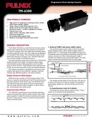
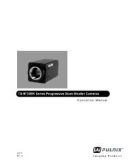
1.1 Features and Applications<br />
The TM-1001-02 is a state-of-the-art CCD camera<br />
which uses a 1 inch 1K x 1K progressive scan interline<br />
transfer CCD imager.<br />
This CCD camera offers outstanding compactness,<br />
high resolution, built-in frame memory, asynchronous<br />
reset, electronic shutter, and digital output as well as<br />
analog video and a number of technical innovations.<br />
The camera's various features allow for versatile<br />
applications, such as high resolution image capturing,<br />
machine vision, computer graphics, gauging, avionics,<br />
microscopy, medical imaging, character and fine<br />
pattern recognition, document reading and high end<br />
surveillance.<br />
Miniaturized and Light Weight<br />
All PULNiX cameras are built with the same design<br />
principles: Solid state technology; miniaturization;<br />
application-specific such as custom design, remote<br />
imagers, special functions for various application<br />
needs; robust design even for military applications.<br />
Imager<br />
The TM-1001-02 uses a 1K x 1K progressive scan<br />
interline transfer CCD. The reason for such CCD is:<br />
1. High resolution (1024 x 1024 active pixels)<br />
For very high resolution and image quality.<br />
2. Square pixel (9.0 x 9.0 µm)<br />
Precise dimensional measurement ability.<br />
3. High speed electronic shutter capability<br />
High dynamic resolution of moving object and<br />
electronic iris control.<br />
Eliminates need for mechanical shutter.<br />
4. Progressive scan<br />
Eliminates interlace deterioration of image.<br />
Ease of computer interface.<br />
5. High sensitivity and low noise at fast scanning<br />
Can drive faster than 20 MHz pixel clock rate.<br />
Excellent S/N ratio (>50 dB).<br />
Micro lens built-in for TM-1001-02<br />
Frame Memory and Digital Output<br />
The TM-1001-02 has a built-in frame grabber and a<br />
frame memory.<br />
The 8-bit A/D converter provides 256 gray levels with<br />
maximized signal-to-noise ratio. The output can be real<br />
time digital output or a captured image (frozen picture).<br />
The digital output format is RS-422 differential output.<br />
Due to the speed limitation, display mode (double<br />
speed read out) is not available from the digital port.<br />
Asynchronous Image Capturing<br />
The TM-1001-02 captures async reset images and<br />
provides continuous video output of the same image.<br />
This makes it simpler for an ordinary frame grabber to<br />
capture the async reset images.<br />
Integration<br />
The TM-1001-02 is capable of capturing high<br />
resolution integration images. The integration can last<br />
from 1/15 sec. to a few seconds. For uniform and low<br />
noise integration, PULNiX offers a peltier-cooled CCD<br />
option.<br />
Display Mode<br />
Since 1K x 1K cameras are not TV format (RS-170,<br />
etc.) the display of the video signal is only achieved by<br />
using a frame grabber and computer or special<br />
monitor.<br />
The TM-1001-02 has a display mode feature which<br />
scans the frame memory read out two times per input<br />
frame. This way it converts the frame rate from 15<br />
frame/sec. to 30 frame/sec. PULNiX PVM series<br />
monitors or equivalent B/W monitors can display 1000<br />
by 1000 pixel counts.<br />
Consult PULNiX for display monitor information.<br />
Asynchronous Reset<br />
The TM-1001-02 can be reset with an external reset<br />
pulse (VINIT).When VINIT is enabled at the Async<br />
mode, the camera keeps discharging from the CCD<br />
and with VINIT leading edge (negative going pulse), it<br />
resets the internal timing and starts integrating the<br />
image for the preset period of shutter timing and<br />
outputs the async shutter video. This feature is<br />
especially important to capture moving objects at the<br />
precise location of the field of view such as a conveyer<br />
belt, fast event observation and still picture capturing.<br />
NOTE: PLEASE ALLOW 5 SEC. DELAY BEFORE<br />
RESTARTING THE CAMERA BECAUSE OF<br />
THE PLD DOWNLOADING.<br />
2
2. SPECIFICATIONS<br />
Imager<br />
Imager<br />
1" Progressive scan interline transfer CCD<br />
Total pixels<br />
1024 (H) x 1024 (V)<br />
Photosensitive pixels 1008 (H) x 1018 (V) 6 + 10 ob(H), 4 + 2 ob (V)<br />
Photosensitive area<br />
9.1 (H) x 9.2 (V) mm<br />
Pixel size 9.0 (H) x 9.0 (V) µm<br />
Output sensitivity<br />
12 µV/e-<br />
Micro lens<br />
Built-in<br />
Blemish Point defect Cluster Column<br />
Class 0 No defect 0 0<br />
Class 1
TM-1001-02 1K X 1K HIGH RESOLUTION ASYNCHRONOUS RESET FULL FRAME SHUTTER CAMERA<br />
The TM-1001-02 is designed to accommodate a high resolution, ON-LINE inspection reset mechanism with full<br />
frame shutter. It takes external horizontal sync to lock the camera and VINIT pulse for resetting the camera<br />
asynchronously.<br />
The shutter speed can be controlled by either an external double pulse or internal shutter speed control with a<br />
10-position dial switch on the back panel.<br />
1. Discharge Principle of CCD<br />
1.1 Substrate Drain Shutter Mechanism<br />
Normal operation requires the CCD chip to construct an individual potential well at each image cell. The potential<br />
wells are separated from each other by a barrier. The barrier is sequentially removed to transfer the charge from<br />
one cell to another by pixel clock. This is the basic principle of the CCD operation for charge transfer.<br />
The substrate drain vertically moves the charges. When excess potential is applied to the substrate underneath<br />
each cell, a potential barrier is pulled down to release the charge into the drain. This can happen to all the cells<br />
simultaneously, whereas normal CCD shuttering is achieved with a horizontal charge shift to the drain area by<br />
interline transferring or reverse transferring of the frame transfer chip.<br />
Surface<br />
Photo cell potential distribution<br />
CCD surface +<br />
Potential barrier<br />
Si substrate<br />
Charge drain to substrate<br />
Vsub = normal mode<br />
Vsub = shutter mode<br />
1.2 Asynchronous Shutter<br />
For Async Shutter mode, provide external Hd for phase locking. When the negative going reset pulse is applied,<br />
the camera will latch the falling edge to its next horizontal drive and reset vertical sync timing immediately.<br />
Therefore, the horizontal phase won't be interrupted. The TM-1001-02 asynchronous camera outputs a full frame<br />
of shuttered video in progressive scanning format from a frame buffer. The frame buffer is updated upon receiving<br />
negative reset pulse.<br />
VINIT<br />
ASYNC RESET<br />
VD<br />
SG (TRANSFER GATE)<br />
DISCHARGE PULSE<br />
PROGRESSIVE OUTPUT<br />
VIDEO<br />
OLD VIDEO<br />
IN MEMORY<br />
SHUTTER<br />
VIDEO<br />
SAME VIDEO FROM<br />
FRAME MEMORY<br />
4
2. Shutter Speed Control<br />
2.1 External pulse width control mode<br />
External<br />
Double<br />
width pulse<br />
X<br />
Hd<br />
Internal Vinit<br />
9H<br />
Transfer Gate<br />
Pulse<br />
Discharge pulse<br />
9H<br />
X<br />
Exposure Time<br />
Composite<br />
Video<br />
For External Pulse Mode, set dial switch to "9". Apply a pulse width control VINIT signal, which can be generated<br />
from an external event trigger, to the camera. Internal reset pulse will be latched to Hd and at the 9th Hd timing<br />
from an external pulse leading edge (negative going edge), CCD discharge pulse is generated to clear the<br />
images. The internal VINIT is generated at the following edge ( positive going edge ) of the external pulse and it<br />
resets internal timing including the video sync. The shutter speed is the same as the external pulse width but the<br />
integration delays 9H from the leading edge. For immediate reset option, please contact PULNiX.<br />
One frame of video output will start from the rising edge of the pulse width control for progressive format.<br />
The camera will output the same video from memory when VINIT is kept high (5V) and update the image upon<br />
receiving next pulse. At async mode, with external pulse input high, the video output is disabled as the camera<br />
keeps discharging the CCD image and only provides black video.<br />
2.2 Internal Fast Reset Mode<br />
External pulse<br />
min. 2H<br />
Hd<br />
Internal Vinit<br />
9H<br />
Transfer Gate<br />
Pulse<br />
Purge pulse (discharge)<br />
Exposure Time<br />
Composite<br />
Video<br />
For Internal Fast Reset Mode, set the 10-position dial switch from "1" to "4". When fast reset mode is selected,<br />
the camera resets with internal VINIT timing, which is latched to Hd, and video output is also synchronized with<br />
internal VINIT timing without further delay. The shutter speed is controlled by the dial switch.<br />
5
2.3 Internal Slow Reset Mode<br />
External pulse<br />
min. 2H<br />
Hd<br />
Internal Vinit<br />
Transfer Gate<br />
Pulse<br />
Discharge pulse<br />
9H<br />
9H<br />
EXPOSURE TIME<br />
Composite<br />
Video<br />
With the Internal Slow Reset mode selected, the camera operates the reset and shutter in the same manner as<br />
the external Double Pulse mode. When external VINIT pulse is applied, internal VINIT is latched to Hd and the<br />
second internal VINIT signal is generated to set up the shutter speed period. The shutter speed is controlled by<br />
setting the dial switch from "5" to "8". Video output timing starts right after the second internal VINIT. For the<br />
timing of the second internal reset, the LPULSE output of 31-pin connector can be used.<br />
3. Signal Board Layout and Adjustment<br />
VR1 VR2 VR3<br />
AGC MGC AGC<br />
MAX<br />
AGC MGC<br />
W1<br />
U2<br />
1310<br />
U3<br />
OFF<br />
VR6 W2<br />
ON<br />
RG<br />
Signal Bd(top side) Rev. A<br />
A<br />
W3<br />
D<br />
U3<br />
1310<br />
VR5<br />
PED<br />
W1 AGC/MGC Left: AGC<br />
Right: MGC<br />
W2 Gamma Down: On (0.45)<br />
Up: Off (1.0)<br />
W3 Analog/Digital Up: Analog direct<br />
Down: Through A/D, D/A<br />
VR1 AGC Set at 2.5 V<br />
VR2 MGC Set at 3.0V±0.4V<br />
VR3 AGC MAX Set at 1.5 V<br />
VR5 PED Set at 50 mV of video<br />
VR6 RG Factory adjustment only<br />
Memory Board Layout and Adjustment<br />
VR1 VR2<br />
VR1 A/D Vref Factory set bit count at<br />
10±4<br />
VR2 D/A Vref Set A/D input=D/A output<br />
U7<br />
U1<br />
Memory Bd(bottom side) Rev.A<br />
6
4. Sync Board<br />
PLL<br />
VR1<br />
DC-DC<br />
13<br />
Potentiometers<br />
VR1 PLL<br />
Set at mechanical center<br />
U2<br />
J5<br />
1<br />
Sync Bd(top side) Rev. A<br />
5. Imager Board<br />
Jumper Setting<br />
Set W1 Short (GND)<br />
VR1<br />
Vsub<br />
Voltage Setting<br />
Set VR1 Vsub Factory Adjustment Only<br />
W1<br />
Imager Bd(rev.A)<br />
5. Digital Output Connector<br />
An EIA-422 digital output is available from 31-pin high-rel, micro-miniature connector (Airborn MP221-031-243-<br />
2200). The mating connector can be firmly secured to the receptacle for vibration and shock environments.<br />
A common D-sub connector was not used to prevent any vibration problems.<br />
16<br />
31<br />
17<br />
1<br />
Pin No Signal Description<br />
1 CLK+ Pixel clock (20.034 MHz) output<br />
17 CLK- "<br />
2 LDV+ Line data valid<br />
18 LDV- "<br />
3 FDV+ Frame data valid<br />
19 FDV- "<br />
4 GND<br />
20 VINIT External Vinit input (TTL)<br />
5 EXT. HD Ext. HD sync input (TTL)<br />
21 EXT.VD Ext. VD sync input (TTL)<br />
6 INTEG. CONT Integration control input active: Low(TTL)<br />
22 ENINT Enable integration for frame capture (TTL)<br />
7 LPULSE Last pulse for slow mode async pulse<br />
23 GND<br />
8 - 15 DO0+ - DO7+ Digital video output ( 8-bit )<br />
24 - 31 DO0 - - DO7- "<br />
16 GND<br />
7
6. Connector Pin Configurations<br />
3<br />
2<br />
4<br />
1<br />
10<br />
5<br />
9<br />
11 12<br />
6<br />
8<br />
7<br />
SH CONTROL<br />
9<br />
8<br />
7<br />
6<br />
0 1 2<br />
3<br />
12-PIN Connector<br />
1. GND 7. VD In<br />
2. +12V DC 8. GND<br />
3. GND 9. HD In<br />
4. Video Out 10. GND<br />
5. GND 11. Integration Control<br />
6. VINIT In 12. GND<br />
5<br />
4<br />
Shutter Control Switch<br />
Manual shutter mode Async reset mode<br />
0 no shutter no shutter<br />
1 1/60 1.0H 1/16000<br />
2 1/125 2.0H 1/8000<br />
3 1/250 4.0H 1/4000<br />
4 1/500 8.0H 1/2000<br />
5 1/1000 16 H 1/1000<br />
6 1/2000 32 H 1/500<br />
7 1/4000 64 H 1/250<br />
8 1/8000 128H 1/125<br />
9 1/16000 Ext. pulse width<br />
Mode 0:<br />
Mode1-4:<br />
Mode5-8:<br />
Mode 9:<br />
Normal mode<br />
Fast mode<br />
Slow mode<br />
Ext. pulse width<br />
7. Monitor Display Mode<br />
One of the advantages of the TM-1001-02 is the built-in scan conversion circuit; so that even though the<br />
progressive scanning frequency is too slow to display on a monitor, the double speed output is provided as<br />
analog video format at 31.50 KHz horizontal and 30 Hz vertical frequency.<br />
For the monitor information, select the switch on the back panel for DSP (double speed).<br />
The double speed output is intended for analog output and it may not be operable with digital format as the<br />
double speed video frequency is too high for standard RS-422 output ( it may work through RS-422 but PULNiX<br />
cannot guarantee the performance ).<br />
For digital output application, select the switch to NSP (normal speed).<br />
Non-interlace Black and White Monitors<br />
PULNiX offers a slow-decay phosphor CRT type non-interlace monitor (42-5001).<br />
Electrohome EVM942 /1242 or equivalent model can be used for TM-1001-02 display mode.<br />
Some of these monitors may not accept 30 Hz vertical sync. Please contact PULNiX for the modification or<br />
information.<br />
8. Frame Memory<br />
The TM-1001-02 has a built-in frame memory which outputs progressive scanning images at 30Hz rate (30<br />
frames per sec). This feature provides the following advantages:<br />
1. Asynchronously captured images are output as standard continuous video signals so that a monitor or frame<br />
grabber can display or process without a special asynchronous video grabber.<br />
2. Integration video is continuously output until the next capture. Normally, the camera cannot output the video<br />
signal during the integration, and the periodic integration causes a blinking video signal. The TM-1001-02<br />
memory keeps the stored image until the next image is completed so that there is no blank interval during<br />
integration.<br />
3. Digital format of the video output can be used as direct interface with the computer. The format is progressive.<br />
8
How to activate the frame memory?<br />
A. Asynchronous reset mode (Select switch on the back panel for ASY...async)<br />
When External VINIT is high (5V), the TM-1001-02 expects the async pulse input. It resets at the negative going<br />
pulse edge and captures the frame regardless of the shutter speed (fast or slow mode). The video output is kept<br />
disabled as the CCD is discharged continuously during VINIT high. When the first VINIT pulse comes in, it resets<br />
the timing and captures the image. The captured image is kept until the next pulse is applied for a new image.<br />
If the switch is NRM (normal mode....<strong>manual</strong> shutter mode), the video output is real time with <strong>manual</strong> shutter.<br />
B. Integration<br />
Activate EN INT (Enable Integration) of 31-pin connector (#22) by connecting to GND then input INTEG<br />
control(#6) as active low (TTL). When it is low, the TM-1001-02 keeps integrating and, upon the rising edge of the<br />
INTEG control pulse, it captures the frame and keeps it until next end of integration. When EN INT is high (open),<br />
video output is in real time without freezing and one frame of the integrated image appears upon ending of<br />
INTEG control pulse (during INTEG control low, it keeps the previous image but when INTEG is high it only holds<br />
one fame). FDV(Field Data Valid) is disabled during the integration and the vertical pulse starts when the image<br />
is output.<br />
9. Progressive scanning<br />
Standard TV system scanning is 525 line interlace scanning as specified in RS-170. Every other horizontal line<br />
(ODD lines and EVEN lines) is scanned at a 60Hz rate per field, and completes scanning with two fields (one<br />
Frame) at 30Hz rate. Because of the interlace scanning, the vertical resolution of CCD cameras is limited at 350<br />
TV lines regardless of the horizontal resolution. When the electronic shutter is applied, the CCD can only hold<br />
one field of charges at each exposure. Therefore, the vertical resolution of the electronic shutter camera is only<br />
244 TV lines.<br />
This is the same situation for a HDTV format camera, since it is interlaced scanning and the vertical resolution of<br />
the shuttered image is 500 lines.<br />
The TM-1001-02 uses a state-of-the-art CCD called a "Progressive scanning interline transfer CCD" which scans<br />
all lines sequentially from top to bottom at one frame rate (15Hz). Like a non-interlace computer screen, it<br />
generates a stable crisp image without alternating lines and provides full vertical TV resolution of 1000 lines (a<br />
monitor display may not be able to show 1000 lines due to monitor resolution of 30Hz scanning).<br />
The interline transfer architecture is also important to generate simultaneous shuttering. This is different from full<br />
frame transfer architecture which requires a mechanical shutter or strobe light in order to freeze the object<br />
motion.<br />
The TM-1001-02 outputs the progressive scanned image with an electronic shutter in three different<br />
formats:<br />
1. Progressive scanning analog output (Jumper W3 of top board set on "A" side)<br />
Straight forward signal output without going through 8-bit A/D, D/A converter. It is useful for higher gray level<br />
resolution than 8-bit (256 levels). It is a real-time CCD output through normal analog video processing into 75Ω<br />
1Vp-p output format (15 Hz ).<br />
2. Progressive scanning digital and analog output (Jumper W3 set on "D"side)<br />
The CCD signal goes through A/D and D/A converters. The frame memory is capable of capturing async and<br />
integration video without having special frame grabbers.<br />
The analog output is the same as 75Ω, 1Vp-p format at 15Hz rate available from BNC and 12-pin connector.<br />
The digital output is available from 31-pin connector with EIA-422 format (20MHz clock rate).<br />
3. Double speed scanning output (Display output)<br />
By setting W13 jumper to double speed mode (open) on the top board, the TM-1001-02 outputs double speed<br />
video for monitor display. It repeats twice from one frame of input video. The digital output of the 31-pin connector<br />
is also at 30 Hz with a 40MHz pixel clock. When a digital cable is short in length it may be usable but PULNiX can<br />
not guarantee proper operation.<br />
9
10. Digital output pulses<br />
Digital Video<br />
Differential line-driven, 8-bit parallel signal with EIA-422 format.<br />
100Ω output termination impedance.<br />
Output from 31-pin connector. The mating connector: Airborne MP211-031-113-4300<br />
Please consult digital cable information. eg. 50-1301-01, 30DG-02, 2m cable<br />
Line Data Valid (preliminary)<br />
Differential line-driven signal with EIA-422 format.<br />
It is active high (+ side is higher than - side) during the transfer of each line of data........Horizontal line read out.<br />
HD<br />
LDV<br />
1.7N<br />
(NSP MODE)<br />
DIGITAL<br />
DATA<br />
11N<br />
128N<br />
266N<br />
1H = 1272N<br />
1006N<br />
(VIDEO OUT)<br />
Note:<br />
For OP.7-3, 10MHz clock,<br />
1N = 99.83 nsec (10.017 MHz)<br />
1H = 126.98 µsec (7.875 KHz)<br />
Frame Data Valid (preliminary)<br />
Differential line-driven signal with EIA-422 format. It is active high during the transfer of each frame data. During<br />
integration, both LDV and FDV are kept low and restart upon the completion of integration.<br />
Pixel clock<br />
PIXEL CLOCK: 1N = 49.92 nSec.........20.034MHz<br />
Differential line-driven signal with EIA-422 format. The frequency is 20.034 MHz (standard) or 40.068MHz (DSP).<br />
VD<br />
34H<br />
VIDEO OUT<br />
1016H<br />
FDV<br />
(NSP MODE)<br />
9H<br />
1050H<br />
1/15 SEC<br />
where 1H=63.49 µsec<br />
FDV<br />
(DSP MODE)<br />
35H<br />
9H<br />
1/30 SEC<br />
VIDEO OUT<br />
1015H<br />
35H<br />
9H<br />
1/30 SEC<br />
VIDEO OUT<br />
1015H<br />
For OP 7-3, the vertical<br />
frequency is 1/7.5 sec<br />
(NSP) and 1/15 sec<br />
(DSP)<br />
where 1H=31.75 µsec<br />
49.9 nsec<br />
NSP<br />
MODE<br />
PIXEL CLOCK<br />
49.9 nsec<br />
DIGITAL DATA<br />
8 nsec<br />
CDS DELAY = 3N<br />
FRAME MEMORY DELAY = 4N<br />
10
11. Signal Delay<br />
CCD<br />
CDS<br />
AGC<br />
3N<br />
A/D M<br />
DOUT<br />
7N<br />
D/A<br />
8N<br />
VAMP<br />
9N<br />
VOUT<br />
PIXEL CLOCK : 1N<br />
TM-1001-02 SIGNAL DELAY<br />
12. Connector and cable<br />
Digital output connector is optional.<br />
Mating connector ordering information: PULNiX part No. 15-1623 Airborne P/N: MP211-031-113-3400<br />
Straight Backshell (cover): 15-1624 MM254-031-000-0000<br />
Cable assembly: Digital cable 30DG-02 50-1301-03<br />
12-pin connector and cable: Standard cable is 12P-02 (2m, 8 conductor cable) for power and external controls.<br />
13. Physical Dimensions<br />
135 12.6 13<br />
44<br />
PULNiX<br />
NRM ASY DSP NSP<br />
POWER<br />
VIDEO<br />
SHUTTER<br />
16<br />
VIDEO OUT<br />
1<br />
48<br />
56<br />
PROGRESSIVE TM-1000SCAN<br />
31<br />
17<br />
M3x0.5 (4x)<br />
3/8"-16<br />
32<br />
44.00 mm 18.00 mm<br />
10.2 mm<br />
35.5 mm<br />
1/4"-20<br />
11
14. TM-1001 PIXEL MAP AND TIMING CHART<br />
14.1 TM-1001 Horizontal pixel mapping<br />
HD<br />
128<br />
TOTAL CLOCK PER 1H = 1272<br />
1017<br />
1021<br />
O.B.<br />
DUMMY<br />
1030<br />
1032<br />
1<br />
DUMMY<br />
6<br />
O.B.<br />
12<br />
13<br />
24<br />
ACTIVE PIXEL<br />
1016<br />
1020<br />
240<br />
CCD OUTPUT<br />
BLANK<br />
266<br />
PIXEL CLOCK<br />
CCD LINE CONTENT<br />
1<br />
DUMMY<br />
6<br />
7<br />
OPTICAL BLACK<br />
12<br />
13<br />
ACTIVE PIXEL<br />
1020<br />
1021<br />
OPTICAL BLACK<br />
1030<br />
1032<br />
DUMMY<br />
14.2 Vertical frame timing<br />
VD<br />
9H<br />
TOTAL HORIZONTAL SCANNING = 1050H<br />
HORIZONTAL LINES<br />
4 O.B.<br />
1020<br />
1021<br />
1024<br />
1049<br />
1050<br />
1<br />
2 O.B.<br />
3<br />
5<br />
1018 ACTIVE PIXELS<br />
1020<br />
VIDEO OUTPUT<br />
BLANK = 34H<br />
(NSP MODE)<br />
12
DIGITAL CABLE ASSEMBLY<br />
30DG-02<br />
P/N 50-1301-03 Full function cable<br />
TM-1001-02 PIN CONFIGURATIONS<br />
16<br />
1<br />
Pin Signal Cable<br />
Pin Signal Cable<br />
31<br />
TM-1001-02 TM-9700 31-pin connector<br />
17<br />
1 CLK+ OR 1RED<br />
2 LDV+ GRY 1RED<br />
3 FDV+ WHT 1RED<br />
4 GND YLW 1RED<br />
5 HD PINK1RED<br />
6 INTEG OR 2RED<br />
7 L PULSE GRY 2RED<br />
8 D0+ WHT 2RED<br />
9 D1+ YLW 2RED<br />
10 D2+ PINK2RED<br />
11 D3+ OR 3RED<br />
12 D4+ GRY 3RED<br />
13 D5+ WHT 3RED<br />
14 D6+ YLW 3RED<br />
15 D7+ PINK3RED<br />
16 N/C<br />
17 CLK- OR 1BLUE<br />
18 LDV- GRY 1BLUE<br />
19 FDV- WHT 1BLUE<br />
20 VINIT YLW 1BLUE<br />
21 VD PINK1BLUE<br />
22 EN INTEG OR 2BLUE<br />
23 GND GRY 2BLUE<br />
24 D0- WHT 2BLUE<br />
25 D1- YLW 2BLUE<br />
26 D2- PINK2BLUE<br />
27 D3- OR 3BLUE<br />
28 D4- GRY 3BLUE<br />
29 D5- WHT 3BLUE<br />
30 D6- YLW 3BLUE<br />
31 D7- PINK3BLUE<br />
37-PIN D-SUB CONNECTOR PIN CONFIGURATIONS<br />
19<br />
37<br />
37-pin D-SUB connector rear view<br />
20<br />
1<br />
Pin Signal Cable<br />
1 CLK+ OR 1RED<br />
2 LDV+ GRY 1RED<br />
3 FDV+ WHT 1RED<br />
4 N/C<br />
5 N/C<br />
6 N/C<br />
7 N/C<br />
8 D0+ WHT 2RED<br />
9 D1+ YLW 2RED<br />
10 D2+ PINK 2RED<br />
11 D3+ OR 3RED<br />
12 D4+ GRY 3RED<br />
13 D5+ WHT 3RED<br />
14 D6+ YLW 3RED<br />
15 D7+ PINK 3RED<br />
16 GND YLW 1RED<br />
17 VINIT YLW 1BLUE<br />
18 EN INTEG OR 2BLUE<br />
19 N/C<br />
Pin Signal Cable<br />
20 CLK- OR 1BLUE<br />
21 LDV- GRY 1BLUE<br />
22 FDV- WHT 1BLUE<br />
23 GND GRY 2BLUE<br />
24 N/C<br />
25 N/C<br />
26 N/C<br />
27 D0- WHT 2BLUE<br />
28 D1- YLW 2BLUE<br />
29 D2- PINK 2BLUE<br />
30 D3- OR 3BLUE<br />
31 D4- GRY 3BLUE<br />
32 D5- WHT 3BLUE<br />
33 D6- YLW 3BLUE<br />
34 D7- PINK 3BLUE<br />
35 GND Shield SHIELD<br />
36 N/C<br />
37 INTEG OR 2RED<br />
13
Notice<br />
The material contained in this <strong>manual</strong> consists of information that is proprietary to <strong>Pulnix</strong> America, Inc., and may<br />
only be used by the purchasers of this product. <strong>Pulnix</strong> America, Inc. makes no warranty for the use of its products<br />
and assumes no responsibility for any errors which may appear or for damages resulting from the use of the<br />
information contained herein. <strong>Pulnix</strong> America, Inc. reserves the right to make changes without notice.<br />
Warranty<br />
All our solid state cameras have a full three year warranty. If any such product proves defective during this<br />
warranty period, <strong>Pulnix</strong> America, Inc. will repair the defective product without charge for parts and labor or will<br />
provide a replacement in exchange for the defective product. This warranty shall not apply to any damage, defect<br />
or failure caused by improper use or inadequate maintenance and use.<br />
Revised Printing: January, 1996<br />
<strong>Pulnix</strong> America, Inc.<br />
1330 Orleans Drive,<br />
Sunnyvale, CA 94089<br />
Tel: (408) 747-0300<br />
(800) 445-5444<br />
Fax: (408) 747-0660<br />
14