User manual (PDF) - JAI Pulnix
User manual (PDF) - JAI Pulnix
User manual (PDF) - JAI Pulnix

You also want an ePaper? Increase the reach of your titles
YUMPU automatically turns print PDFs into web optimized ePapers that Google loves.
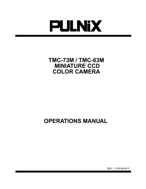
TMC-73M / TMC-63M<br />
MINIATURE CCD<br />
COLOR CAMERA<br />
OPERATIONS MANUAL<br />
REV. 1, P/N 69-0017
TABLE OF CONTENTS<br />
1. OPERATION ........................................................................................................................ 3<br />
1.1 Outline .............................................................................................. 3<br />
1.2 Special Characteristics of a CCD ....................................................... 3<br />
2. COMPREHENSIVE SPECIFICATIONS ................................................................................. 4<br />
3. THEORY OF OPERATION .............................................................................................. 4<br />
3.1 Operation Principles of the CCD ....................................................... 4<br />
3.2 Mechanism of the CCD Electrical Charge Transmission ................ 5<br />
3.3 The Interline-Transfer Organization of the CCD Image Sensors ................ 6<br />
3.4 Instructions for Powering TMC-73M/TMC-63M ............................. 6<br />
4. ALIGNMENT AND ADJUSTMENT ................................................................................. 8<br />
4.1 Equipment .................................................................................. 8<br />
4.2 Preparation ................................................................................. 9<br />
4.3 Adjustment Procedures .................................................................... 9<br />
5. OPERATION ........................................................................................................................ 11<br />
6. IMAGER COLOR FILTERS<br />
6.1 Diagram of Complementary Mosaic Filter .......................................... 11<br />
6.2 Spectral Response With Optical Filter (IR Cut Filter) ............................. 11<br />
7. TIMING CHART ........................................................................................................... 12<br />
8.SERIAL DATA INPUT FORMAT ................................................................................. 13<br />
9. MECHANICAL DRAWINGS ................................................................................. 14<br />
9.1 Standard Configuration .................................................................... 14<br />
9.2 OEM internal board assembly ....................................................... 14<br />
2
SECTION 1: OPERATION<br />
1.1 OUTLINE<br />
The TMC-73M (NTSC model) / TMC-63M (PAL<br />
model) is a super-miniature color video camera which<br />
uses a 1/3" high resolution solid state image sensor -<br />
the Charge Coupled Device (CCD). The CCD camera<br />
produces less geometrical distortion and has higher<br />
resistance to vibration and shock when compared with<br />
a camera using a pickup tube. These features make<br />
the camera suitable for both industrial and CCTV<br />
surveillance applications. It is also suitable as an input<br />
device in an image processing system since the TMC-<br />
73M offers superb color reproduction.<br />
The TMC-73M series cameras feature separate outputs<br />
for Y/C output and standard VBS output.<br />
All models have external access switches to select the<br />
white balance for outdoor(5600°K) and indoor<br />
(3200°K). The TMC-73M series uses complementary<br />
stripe color filters of Cy, Gr, Ye to generate all color<br />
variations. The complementary color system has the<br />
advantage of better sensitivity than the primary color<br />
system of R, G, B.<br />
All models use CS-mount lenses and C-mount lenses<br />
with a adapter.<br />
1.2 SPECIAL CHARACTERISTICS OF A CCD<br />
Smear phenomenon<br />
This phenomenon occurs when shooting a very bright<br />
object (such as electronic light, fluorescent lamp, the<br />
sun or a strong reflection.) Due to the interline-transfer<br />
organization of the CCD image sensors (Refer to the<br />
"The Interline-transfer Organization of the CCD Image<br />
Sensors", Section 3.3), this phenomenon is caused by<br />
electronic charges generated beneath the photosensors<br />
by a light with a long wavelength, such as an<br />
infrared light.<br />
NOTE: PULNiX color cameras contain a filter to minimize<br />
smear. Smear should only occur under extremely<br />
bright, and point light source conditions.<br />
Patterned noise on the picture at<br />
high temperatures<br />
Dark current (thermal noise) is inherent in semiconductors.<br />
At room temperature, the amount of dark<br />
current in all photosensors is very close. However, as<br />
the temperature rises, the amount of dark current<br />
increases. As a result, the relative difference between<br />
the dark current of each photosensor increases. This difference<br />
also causes the patterned noise on the picture.<br />
Light streak.....Smear<br />
Very bright object<br />
False signal<br />
When vertical stripes or straight lines are shot, they<br />
may look wavy ( Moire effect ).<br />
Blemish-free imagers<br />
CCD photosensor elements generate electronic<br />
charges which ultimately produce horizontal and vertical<br />
rows in the CCD image sensor. Thus, any malfunctioning<br />
photosensor element could eventually cause a<br />
blemish on the monitor screen. However, the PULNiX<br />
TMC-73M/TMC-63M cameras all have blemish-free<br />
CCDs to avoid this problem.<br />
Consult the specifications in "Comprehensive<br />
Specifications" for details on the blemishes of the<br />
TMC-73M/TMC-63M.<br />
At room temperature<br />
At high temperature<br />
Level of dark current<br />
3
SECTION 2: COMPREHENSIVE SPECIFICATIONS<br />
Model TMC-73M (NTSC) TMC-63M (PAL)<br />
Imager<br />
1/3" interline transfer CCD (4.8 x 3.6 mm)<br />
Pixel<br />
Cell size<br />
768(H) x 494(V)<br />
6.35µm(H) x 7.4µm(V)<br />
752(H) x 582(V)<br />
6.5µm(H) x 6.25µm(V)<br />
Color filter<br />
Scanning<br />
Cy, Ye, Mg, G complementary color filter<br />
2:1 interlaced, field mode scanning<br />
525 lines, 59.94 Hz 625 lines, 50 Hz<br />
Sync<br />
Internal sync only<br />
fH = 15.734 KHz<br />
fH = 15.625 KHz<br />
fV = 59.94 Hz<br />
fV = 50.00 Hz<br />
TV resolution<br />
S/N ratio<br />
Min. illumination<br />
Video output<br />
460(H) x 400(V) TV lines450(H) x 450(V) TV lines<br />
50 dB (AGC off )<br />
2 Lux F = 1.4 (AGC on)<br />
VBS = 1.0 Vp-p at 75 Ω (NTSC and PAL)<br />
Y (B/W) = 1.0 Vp-p with sync, Chroma = 285 mV at 75 Ω (Y/C or S-VHS )<br />
Color balance<br />
Manual white balance with daylight and indoor switch<br />
External hue adjustment via serial data interface<br />
AGC<br />
Gamma<br />
Lens mount<br />
Power req.<br />
Operating temp.<br />
Vibration & shock<br />
Size (W X H X L)<br />
Weight<br />
Power cable<br />
Power supply<br />
Auto iris connector<br />
Max. 32 dB AGC, on-off jumper, <strong>manual</strong> gain control and ext. gain control<br />
0.45<br />
CS-mount or C-mount with adapter<br />
12 V DC, 200 mA<br />
-10°C to +50°C<br />
Vibration: 7 G (11Hz to 200Hz), Shock: 70G<br />
40 dia x 78 mm 1.57" D x 3.07" L<br />
150 grams<br />
12P-02 for NTSC/PAL and Y/C, KC-10 for NTSC/PAL only<br />
12VDC, 300mA<br />
Internal wiring only for galvanometric iris drive and iris video output,<br />
Automatic electronic shutter built-in<br />
Functional options<br />
Manual shutter, up to 16 fields integration output, external digital control for<br />
R-Y,B-Y hue, gain, iris level and chroma level<br />
Accessories<br />
CS and C-mount mini lenses<br />
SECTION 3: THEORY OF OPERATION<br />
3.1 OPERATION PRINCIPLES OF THE CCD<br />
A CCD (Charge Coupled Device) consists of MOS<br />
(Metal Oxide-Silicon) capacitors arranged in a regular<br />
array. It performs three functions connected with handling<br />
electrical charges:<br />
Photoelectric conversion (photo sensor)<br />
Incandescent light generates electrical charges on the<br />
MOS capacitors, with the quantity of charge being proportional<br />
to the brightness.<br />
Accumulation of electrical charges<br />
Transmission of electrical charge<br />
When high voltage is applied to the electrodes, a<br />
deeper well is formed. When low voltage is applied, a<br />
shallower well is formed. In the CCD, this property is<br />
used to transmit electrical charge. When a high voltage<br />
is applied to the electrodes, a deep electric potential<br />
well is formed and electrical charge flows in from<br />
the neighboring wells. When this is repeated over and<br />
over among the regularly arranged electrodes, the<br />
electrical charge is transferred from one MOS capacitor<br />
to another. This is the principle of CCD electrical<br />
charge transmission.<br />
When voltage is applied to the electrodes of the CCD,<br />
an electrical potential well is formed in the silicon layer.<br />
The electrical charge is accumulated in this well.<br />
4
3.2 MECHANISM OF CCD ELECTRICAL<br />
CHARGE TRANSMISSION<br />
The TMC-73M uses a 4-phase drive method CCD. For<br />
simplicity, a 2-phase drive method CCD is explained<br />
below.<br />
ø2<br />
ø1<br />
Figure 1 shows an example of the changes which can<br />
occur in potential wells in successive time intervals.<br />
N- N N- N N- N N- N N-<br />
P - sub<br />
At t1, the electrode voltages are fH1>fH2, so the<br />
potential wells are deeper toward the electrode at the<br />
higher voltage fH1. Electrical charge accumulates in<br />
these deep wells.<br />
At t2, the clock voltages fH1 and fH2 are reversed; now<br />
the wells toward the electrode at voltage fH2 become<br />
deeper while those toward the electrode at fH1<br />
become shallower. So the wells at fH2 are deeper than<br />
those at fH1 and the signal charge flows toward the<br />
deeper wells.<br />
At t3, the electrode voltages have not changed since<br />
t2, so the signal charge flows into the wells toward the<br />
electrode at fH2. One transmission of electrical charge<br />
is completed. This action is repeated over and over to<br />
execute the horizontal transmissions.<br />
time<br />
t1<br />
t2<br />
t3<br />
potential profile<br />
transfer direction<br />
Operating Pulse Waveforms (ø1, ø2 or øH1, øH2)<br />
V1<br />
ø2<br />
V0<br />
ø1 V1<br />
V0<br />
V1 > VO<br />
t1 t2<br />
t3<br />
t<br />
Figure 1<br />
potential profile<br />
N, N- * : N type impurity<br />
* - (minus) shows lower<br />
impurity concentration<br />
Vertical transfer<br />
The vertical shift register transfers charges using a<br />
four-phase drive mode. Figure 2 shows an example of<br />
the changes which can occur in potential wells in successive<br />
time intervals. At tO, the electrode voltages are<br />
(V1 = V2)>(V3 = V4), so the potential wells are deeper<br />
toward the electrode at the higher voltages V1 and V2.<br />
Charges accumulate in these deep wells.<br />
At t1, the electrode voltages are (V1 = V2 = V3)>(V4),<br />
so the charges accumulate in the wells toward the<br />
electrode at V1, V2 and V3.<br />
At t2, the electrode voltages are (V2 = V3)>(V4 = V1),<br />
so the charges accumulate in the wells toward the<br />
electrode at V2 and V3. Electrode voltage states at t3<br />
and after are shown below.<br />
t3(V2 = V3 = V4)>(V1)<br />
t4(V3 = V4)>(V1 = V2)<br />
t5(V4>(V1 = V2 = V3)<br />
t6(V4 = V1)>(V2 = V3)<br />
t7(V4 = V1 = V2)>(V3)<br />
t8(V1 = V2)>(V3 = V4) (Initial state)<br />
These operations are repeated to execute the vertical<br />
transfer.<br />
t0<br />
t1<br />
t2<br />
t3<br />
t4<br />
t5<br />
t6<br />
t7<br />
t8<br />
V1<br />
V2<br />
V3<br />
V4<br />
4 Phase CCD Drive<br />
transfer direction<br />
Figure 2<br />
5
3.3 THE INTERLINE-TRANSFER<br />
ORGANIZATION OF THE CCD IMAGE SENSORS<br />
The TMC-73M CCD video camera module adopts an<br />
interline-transfer organization in which the precisely<br />
aligned photosensor and vertical transmission section<br />
are arrayed interlinearly.<br />
A horizontal shift register links up with the vertical<br />
transmission section. Light variations are sensed by<br />
the photosensors which generate electronic charges<br />
proportional to the light intensity. The generated<br />
charges are fed into the vertical shift registers all at<br />
once. The charges are then transferred from the vertical<br />
transmission section to the horizontal shift registers<br />
successively and finally reach the output amplifier to<br />
be read out successively.<br />
Optional output<br />
Each pin has to be designated for various options such<br />
as Y/C output, integration control, etc. The customer<br />
will be required to assign option numbers.<br />
Warning<br />
The TMC-73M must use either the 12P Series or C-10<br />
cable. When applying power to the camera, make<br />
sure that none of the exposed leads on the multiple<br />
conductor cable are touching. This may cause damage<br />
to the camera. Besides the power connector, there<br />
is a standard BNC video connector on the rear of the<br />
camera.<br />
Output section<br />
(818 elements)<br />
(513 elements)<br />
Horizontal<br />
shift register<br />
odd line<br />
even line<br />
odd line<br />
Photo senser<br />
3.4.1 12-PIN CONNECTOR AND POWER<br />
CABLES<br />
12-Pin Connector<br />
TMC-73M/TMC-63M<br />
12P-02 Cable<br />
Vertical shift register<br />
3.4 INSTRUCTIONS FOR POWERING<br />
THE TMC-73M/TMC-63M<br />
1. GND Gray<br />
2. +12V DC In Yellow<br />
3. GND Red Shield<br />
4. Video Out (VBS) Red Coax Signal<br />
5. GND Orange Shield<br />
6. Auto/Man Orange Coax Signal<br />
7. Chroma Black Coax Signal<br />
8. GND White Shield<br />
9. Y (B/W) White Coax Signal<br />
10. D0 Brown<br />
11. D1 Blue<br />
12. D2 Black Shield<br />
Connectors<br />
The TMC-73M requires 12 V DC (200mA). Power is<br />
obtained through the 12-pin connector located at the<br />
rear of the camera. PULNiX offers a 4-conductor<br />
power cable with mating connector (model# C-10). For<br />
Y/C output, use a 12-pin connector to supply power.<br />
12-Pin Figure Power Connector<br />
1 9<br />
2<br />
10<br />
8<br />
3<br />
11 12<br />
7<br />
4<br />
5<br />
6<br />
6
12P Series cables available:<br />
12P-02 2 meters<br />
12P-05 5 meters<br />
12P-10 10 meters<br />
12P-15 15 meters<br />
12P-25 25 meters<br />
12P-X Custom length<br />
12P-02 8-conductor cable for RGB<br />
12P-02MF RGB separator cable (for use with CCA-7<br />
Signal Separator only)<br />
3.4.2 BACK PANEL ASSEMBLY<br />
3.4.4 AUTO SHUTTER AND AUTO IRIS<br />
OUTPUT<br />
The TMC-73M has a built-in autoshutter control<br />
which works as electronic iris so that standard<br />
fixed or <strong>manual</strong> iris lens can be used.<br />
The TMC-73M has auto iris output pads located on the<br />
PWB1. optional output from special connector may be<br />
obtained from PULNIX. The lens mount of the camera<br />
is a standard CS-mount or C-mount with a adapter,<br />
and most standard 1/2" auto iris lenses may be used<br />
with the TMC-73M/TMC-63M.<br />
Color temperature<br />
switch<br />
12-pin connector<br />
D0, D1, D2 are used for <strong>manual</strong> shutter speed control.<br />
.<br />
video<br />
5600<br />
3200<br />
power<br />
Warning:<br />
Do not unplug the auto iris lens from the camera while<br />
the camera is powered. This may damage the lens.<br />
Video<br />
man<br />
auto<br />
Back Panel Assembly<br />
S<br />
P<br />
E<br />
E<br />
D<br />
C<br />
O<br />
NTR<br />
O<br />
L<br />
D0<br />
D1<br />
D2<br />
Shutter<br />
speed<br />
0<br />
L<br />
1<br />
H<br />
2<br />
L<br />
3<br />
H<br />
4<br />
L<br />
5<br />
H<br />
6<br />
L<br />
7<br />
H<br />
L L H H L L H H<br />
L L L L H H H H<br />
1/60 1/125 1/250 1/500 1/1000 1/2000 1/4000 1/10000<br />
3.4.3 COLOR BALANCE ADJUSTMENT<br />
The TMC-73M/TMC-63M cameras feature an<br />
advanced color balancing system which is set to outdoor<br />
condition and indoor condition as factory set.<br />
External digital control is capable to set internal D/A<br />
converter for R-Y, B-Y Hue and chroma level adjustment.<br />
Integration<br />
(option)<br />
2FLD 4FLD 6FLD 8FLD 10FLD 12FLD 14FLD 16FLD<br />
R<br />
MG<br />
YL<br />
70 %<br />
100 %<br />
B<br />
G<br />
CY<br />
7
SECTION 4 :<br />
ALIGNMENT AND ADJUSTMENT<br />
4.1 EQUIPMENT<br />
1. Light source for test chart.<br />
Pattern Box PTB-100 (90-130V)<br />
PTB-220 (190-240V)<br />
2. For video level and gamma adjustment.<br />
Grayscale Chart<br />
White Window Chart<br />
3. For color adjustment.<br />
(Use color bar chart)<br />
YL CY G W MG R B<br />
Color Bar Chart<br />
4. For signal adjustment.<br />
Vectorscope<br />
Waveform monitor<br />
Oscilloscope<br />
YL<br />
R<br />
70 %<br />
100 %<br />
MG<br />
B<br />
5. Standard Pattern Frame<br />
G<br />
CY<br />
8
4.2 PREPARATION<br />
4.2.1 BACK FOCUS ADJUSTMENT (ONLY FOR<br />
OPTIONAL REQUIREMENT)<br />
Subject: Resolution chart<br />
1. Mount the <strong>manual</strong> lens (i.e. Cosmicar 25mm,<br />
F=1.4).<br />
2. Open the lens iris completely and set lens focal<br />
length to minimum for the lens used (e.g. 2 ft.).<br />
3. If image is not focused properly, set back focus as<br />
follows.<br />
4. Unscrew the M2x3 hex screw on the Front Panel<br />
until the focus ring is loose.<br />
5. Adjust the silver back focus ring until the image is<br />
focused.<br />
6. Repeat steps 4 and 5 if needed.<br />
W301, W302 Set to 3200°K<br />
W303 Open (AGC on)<br />
PWB4<br />
VR401 MGC = 2.5 V<br />
VR402 AGC MAX = 3.0 V<br />
VR403 AGC = 2.0 V<br />
VR404 Vsub See Vsub voltage<br />
VR405 IRIS level = 2.0 V<br />
W401<br />
W402<br />
11<br />
J1<br />
6<br />
5<br />
J1<br />
1<br />
J2 2 1<br />
VR403<br />
VR404<br />
VR402<br />
AGC<br />
VR405<br />
Keep open. Use MGC/AGC selection<br />
NTSC... Open, PAL...Short<br />
M<br />
W401<br />
YLOUT<br />
IRIS<br />
CT+<br />
DR+<br />
DR-<br />
M/C<br />
CT-<br />
TP403<br />
TP402<br />
TP401<br />
VR301<br />
PWB4<br />
VR302<br />
PWB3<br />
C-mount Ring<br />
W303<br />
EXT CONT<br />
A/MGC<br />
D/I<br />
CLK<br />
LD<br />
D/O<br />
W301<br />
W302<br />
VR304 VR306 VR308 VR307<br />
VR303 VR305<br />
4.3 TMC-73M ADJUSTMENT PROCEDURES<br />
4.3.1 PRESET<br />
Preset each potentiometer as follows:<br />
PWB1<br />
VR101 Y level = 2.5 V<br />
VR102 SH level = 1.7 V<br />
W101<br />
W102<br />
W103<br />
W104<br />
PWB2<br />
W201<br />
W202<br />
W203<br />
W204<br />
W205<br />
Back Focus<br />
2 Feet<br />
TMC-73M...Open, TMC-63M...Short<br />
TMC-73M...Short, TMC-63M...Open<br />
TMC-73M...Open, TMC-63M...Short<br />
TMC-73M...Open, TMC-63M...Short<br />
TMC-73M...N, TMC-63M...P<br />
Open<br />
NTSC...Open, PAL...Short<br />
NTSC...Open, PAL... Short<br />
Right side (VD)<br />
PWB3<br />
VR301 B-Y GAIN = 2.4 V<br />
VR302 R-Y GAIN = 3.2 V<br />
VR303 R cont 3200 = 3.8V<br />
VR304 R cont 5600 = 4.0 V<br />
VR305 B cont 3200 = 4.0 V<br />
VR306 B cont 5600 = 3.4V<br />
VR307 R-Y Hue = 3.5 V<br />
VR308 B-Y Hue = 3.0 V<br />
9<br />
W204<br />
P N<br />
VR102<br />
TP104<br />
N<br />
W201<br />
P<br />
W205<br />
TP201<br />
TP101 TP102<br />
TP103<br />
W104 W101<br />
VR101<br />
4.3.2 FUNCTION TEST<br />
With above settings, the camera will output a good<br />
picture and you can proceed to the fine tuning process.<br />
4.3.3 WHITE BALANCE<br />
N<br />
W203<br />
P<br />
W202<br />
N<br />
12V IN<br />
GND<br />
Equipment: Color bar chart (3200°K),<br />
Vector scope, Wave form monitor.<br />
Set AGC and White balance selection to Manual side<br />
(short to GND).<br />
Set to auto-shutter off(PWB2, A/M to GND).<br />
Use standard lens (Calibrated ) and set the iris to F=8.<br />
For 5600°K, use blue conversion filter.<br />
Burst level<br />
Confirm that burst level on Vector scope is on the 75 %<br />
line.<br />
A/M<br />
Y OUT<br />
CHROMA<br />
N<br />
P<br />
W102<br />
W103<br />
GND<br />
VIDEO<br />
PWB2<br />
PWB1
R gain, B gain<br />
Confirm that the white spot on Vector scope is in the<br />
center after adjusting white balance.<br />
C1 gain<br />
Confirm that each color dot on the Vector scope<br />
combines into one spot.<br />
4.3.4 Y LEVEL, SETUP LEVEL<br />
Use Waveform monitor.<br />
Observe the waveform and adjust VR101 to set the<br />
white level to 95 IRE.<br />
Put lens cap on and confirm that setup (Pedestal level)<br />
is 7, 5 IRE.<br />
100<br />
80<br />
4.3.7 AGC<br />
Select MGC/AGC to AGC side (open).<br />
Adjust lens to see if AGC is functioning.<br />
Observe the AGC threshold level and adjust AGC<br />
potentiometer if necessary.<br />
4.3.8 SHUTTER CONTROL AND INTEGRATION<br />
CONTROL<br />
Auto-shutter mode (electronic iris)<br />
Set A/M selection to auto mode (Open) and check the<br />
electronic iris change. Adjust VR102 to select the best<br />
lighting condition if the preset is not adequate.<br />
Manual shutter control<br />
Select A/M to <strong>manual</strong> mode (short to GND).<br />
If external control is required,it is necessary to wire D0,<br />
D1, D2 inputs.<br />
The shutter speed is programmed by selecting D0, D1,<br />
D2.<br />
60<br />
40<br />
20<br />
75<br />
10°<br />
0°<br />
10°<br />
Integration mode (Optional)<br />
This integration is synchronous and the interval of the<br />
integration is programmed by selecting D0, D1, D2.<br />
Select SMD1 open and SMD2 low (GND).<br />
Pin #3 WEN can be used as picture grabbing timing.<br />
-20<br />
O E O E O E O E O E O E O E O E O E<br />
VD<br />
-40<br />
2 FIELD INTEGRATION<br />
SG1,SG2<br />
4.3.5 R-Y GAIN, B-Y GAIN, R-Y HUE, B-Y HUE<br />
Use Vector scope.<br />
Adjust VR302 (R-Y gain), VR301 (B-Y gain),<br />
VR307(R-Y Hue), VR308(B-Y Hue) to set each vector as<br />
shown below:<br />
WEN<br />
4 FIELD INTEGRATION<br />
SG1,SG2<br />
WEN<br />
WEN: write enable<br />
Speed control<br />
100<br />
80<br />
60<br />
10°<br />
D0<br />
D1<br />
0<br />
L<br />
L<br />
1 2 3 4 5 6 7<br />
H L H L H L H<br />
L H H L L H H<br />
40<br />
20<br />
0°<br />
D2<br />
Shutter<br />
speed<br />
L L L L H H H H<br />
1/60 1/125 1/250 1/500 1/1000 1/2000 1/4000 1/10000<br />
-20<br />
75<br />
10°<br />
Integration<br />
(option)<br />
2FLD 4FLD 6FLD 8FLD 10FLD 12FLD 14FLD 16FLD<br />
-40<br />
4.3.6 WHITE BALANCE<br />
Adjust VR303 (R cont) and VR305 (B cont) to set the<br />
vector scope white center for 3200°K.<br />
Change jumpers W301 and 302 to 5600°K side.<br />
Adjust VR304 and VR306 with color temperature<br />
conversion filter to set white center.<br />
10<br />
Continuous shutter<br />
By applying a negative going TTL pulse to pin #6 TRIG<br />
input, the TMC-73M can operate with continuous shutter<br />
speed change. The input pulse must move within a field<br />
timing and the shutter speed is between the pulse edge<br />
and SG1, SG2. In order to activate this function, D0, D1,<br />
D2 must all be low (GND). Unless the TRIG pulse is<br />
applied, CCD charges are kept discharging and when<br />
the pulse is input, the discharge stops and integration<br />
starts up to the transfer gate timing (SG1, SG2).
External Digital Control<br />
The TMC-73M has built-in digital communication and<br />
D/A converter which can take serial data input and<br />
provide various function controls.<br />
The standard functions are;<br />
Manual gain control<br />
Iris level control for galvanometric iris lens<br />
Chroma level adjustment<br />
R-Y hue, B-Y hue control<br />
12 bit of serial data controls 8 bit of data and 4 bit of<br />
address data. The D/A output is controlled as increment<br />
of 5/256 V ( = 0.02V) to maximum 5.0 V.<br />
See the data input format section.<br />
SECTION 5: RGB OPERATION (Option)<br />
5.1 CCA-7 RGB “BREAKOUT” MODULE<br />
CCA-7 is a compact device designed to accept camera<br />
outputs via the 12P-02MF (2 - meter) cable from the<br />
camera, and then output the signals (R, G, B, Sync,<br />
and Video) via standard BNC connectors. It also<br />
accepts 12V DC input via a terminal for power.<br />
SECTION 6: IMAGER COLOR FILTERS<br />
6.1 DIAGRAM OF COMPLEMENTARY STRIPE<br />
FILTER<br />
OUTPUT<br />
CY<br />
G<br />
CY<br />
G<br />
G<br />
CY<br />
G<br />
COMPLEMENTARY MOSAIC FILTER<br />
YE<br />
MG<br />
YE<br />
MG<br />
MG<br />
YE<br />
MG<br />
CY<br />
G<br />
CY<br />
G<br />
G<br />
CY<br />
G<br />
YE<br />
MG<br />
YE<br />
MG<br />
MG<br />
HORIZONTAL SHIFT REGISTER<br />
YE<br />
MG<br />
CY<br />
G<br />
CY<br />
G<br />
G<br />
CY<br />
G<br />
V SHIFT REGISTER<br />
YE<br />
MG<br />
YE<br />
MG<br />
MG<br />
YE<br />
MG<br />
6.2 SPECTRAL RESPONSE WITH COMPLE-<br />
MENTARY MOSAIC FILTER<br />
GND +12V<br />
To Camera<br />
(Connect 12P-02MF here)<br />
CCA-7<br />
R G B Sync Video<br />
Note: RGB option is only available when TMC-73M is<br />
modified for use with CCA-7. Contact PULNiX for<br />
further assistance.<br />
Relative Response<br />
1.0<br />
.9<br />
.8<br />
.7<br />
Ye<br />
.6<br />
Cy G<br />
.5<br />
.4<br />
.3<br />
Mg<br />
.2<br />
.1<br />
.0<br />
400 500 600 700<br />
Wavelength (nm)<br />
11
SECTION 7: TIMING CHART FOR TMC-73M/TMC-63M<br />
HD<br />
6.7µSec<br />
96<br />
6 45 70 22 5<br />
818<br />
768 45<br />
CCE photo sensors<br />
allocation<br />
763<br />
764<br />
765<br />
766<br />
767<br />
768<br />
B1<br />
B45<br />
D1<br />
D22<br />
B1<br />
B2<br />
B3<br />
B4<br />
B5<br />
1<br />
2<br />
3<br />
4<br />
5<br />
6<br />
7<br />
8<br />
9<br />
10<br />
757<br />
758<br />
759<br />
760<br />
761<br />
762<br />
763<br />
764<br />
765<br />
766<br />
767<br />
768<br />
B1<br />
B45<br />
69.8nSec<br />
H register<br />
stop period<br />
Optical<br />
black period<br />
Image sensing period<br />
Optical<br />
black period<br />
Dummy<br />
H register<br />
CCD output<br />
signal<br />
Effective picture<br />
period<br />
154<br />
H BLK 10.7µSec<br />
Composite video<br />
output<br />
22<br />
1.54µSec<br />
68<br />
H SYNC<br />
4.75µSec<br />
64<br />
4.47µSec<br />
910<br />
63.56µSec<br />
(1 horizontal line)<br />
756<br />
52.81µSec<br />
12
SECTION 8: SERIAL DATA INPUT FORMAT<br />
LSB<br />
MSB<br />
D0 D1 D2 D3 D4 D5 D6 D7 D8 D9 D10 D11<br />
D/A OUTPUT<br />
ADDRESS DATA<br />
0 0 0 0 0 0 0 0 (5/256) X 1 = 0.02 V<br />
1 0 0 0 0 0 0 0 (5/256) X 2 = 0.04 V<br />
0 1 0 0 0 0 0 0 (5/256) X 3 = 0.06 V<br />
ADDRESS<br />
0 1 1 1 1 1 1 1 (5/256) x 255 = 4.98 v<br />
1 1 1 1 1 1 1 1 (5/256) x 256 = 5.00 v<br />
D8 D9 D10 D11<br />
0 0 0 0 Do not care<br />
0 0 0 1 A01 = Manual gain control 6dB at
SECTION 9: MECHANICAL DRAWINGS<br />
9.1 STANDARD CONFIGURATIONS<br />
70mm<br />
AUTO<br />
MAN<br />
42.65<br />
37mm<br />
PULNiX<br />
AGC MGC<br />
VIDEO<br />
55<br />
32<br />
POWER<br />
82mm<br />
40mm<br />
15<br />
9.2 OEM INTERNAL ASSEMBLY (Flex-Rigid board structure)<br />
30 D<br />
41<br />
38 D<br />
17<br />
14
NOTICE<br />
The material contained in this <strong>manual</strong> consists of information that is proprietary to PULNiX America, Inc.,<br />
and may only be used by the purchasers of this product. PULNiX America, Inc. makes no warranty for the<br />
use of its products and assumes no responsibility for any errors which may appear or for damages<br />
resulting from the use of the information contained herein. PULNiX America, Inc. reserves the right to<br />
make changes without notice.<br />
WARRANTY<br />
All our solid-state cameras have a full three year warranty. If any such product proves defective during<br />
this warranty period, <strong>Pulnix</strong> America, Inc. will repair the defective product without charge for parts and<br />
labor or will provide a replacement in exchange for the defective product. This warranty shall not apply to<br />
any damage, defect or failure caused by improper use or inadequate maintenance and use.<br />
Revised Printing: May, 2002<br />
In Australia<br />
PULNiX America Inc.<br />
Unit 16, #35 Garden Road<br />
Clayton, Vic 3168<br />
Tel: 3-9546-0222<br />
Fax: 3-9562-4892<br />
In the U.K.<br />
PULNiX Europe Ltd.<br />
Aviary Court, Wade Road<br />
Basingstoke, Hants RG24 8PE<br />
Tel: 01256-475555<br />
Fax: 01256-466268<br />
Industrial Products Division<br />
PULNiX America Inc. Tel: 408-747-0300<br />
1330 Orleans Drive Tel: 800-445-5444<br />
Sunnyvale, CA 94089 Fax: 408-747-0660<br />
In Germany<br />
PULNiX Europe Ltd.<br />
Steinbruch 5<br />
D-8755 Alzenau<br />
Tel: 06023-4666<br />
Fax: 06023-4667<br />
In Japan<br />
Takenaka System Co. Ltd.<br />
7-1, Shinomiya Narano Cho<br />
Yamashina-ku, Kyoto, 607<br />
Tel: 075-593-9787<br />
REV. 1, P/N 69-0017