User manual (PDF) - JAI Pulnix
User manual (PDF) - JAI Pulnix
User manual (PDF) - JAI Pulnix

You also want an ePaper? Increase the reach of your titles
YUMPU automatically turns print PDFs into web optimized ePapers that Google loves.
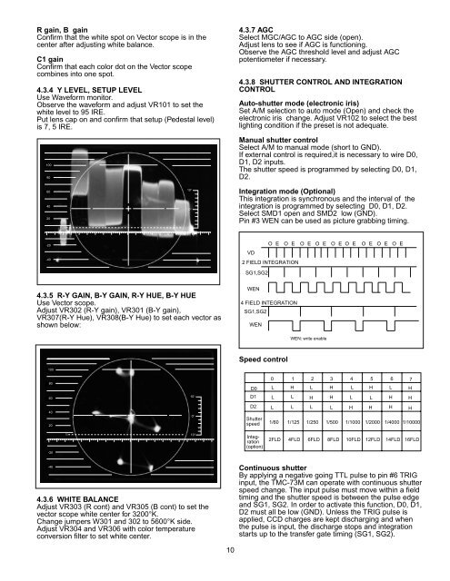
R gain, B gain<br />
Confirm that the white spot on Vector scope is in the<br />
center after adjusting white balance.<br />
C1 gain<br />
Confirm that each color dot on the Vector scope<br />
combines into one spot.<br />
4.3.4 Y LEVEL, SETUP LEVEL<br />
Use Waveform monitor.<br />
Observe the waveform and adjust VR101 to set the<br />
white level to 95 IRE.<br />
Put lens cap on and confirm that setup (Pedestal level)<br />
is 7, 5 IRE.<br />
100<br />
80<br />
4.3.7 AGC<br />
Select MGC/AGC to AGC side (open).<br />
Adjust lens to see if AGC is functioning.<br />
Observe the AGC threshold level and adjust AGC<br />
potentiometer if necessary.<br />
4.3.8 SHUTTER CONTROL AND INTEGRATION<br />
CONTROL<br />
Auto-shutter mode (electronic iris)<br />
Set A/M selection to auto mode (Open) and check the<br />
electronic iris change. Adjust VR102 to select the best<br />
lighting condition if the preset is not adequate.<br />
Manual shutter control<br />
Select A/M to <strong>manual</strong> mode (short to GND).<br />
If external control is required,it is necessary to wire D0,<br />
D1, D2 inputs.<br />
The shutter speed is programmed by selecting D0, D1,<br />
D2.<br />
60<br />
40<br />
20<br />
75<br />
10°<br />
0°<br />
10°<br />
Integration mode (Optional)<br />
This integration is synchronous and the interval of the<br />
integration is programmed by selecting D0, D1, D2.<br />
Select SMD1 open and SMD2 low (GND).<br />
Pin #3 WEN can be used as picture grabbing timing.<br />
-20<br />
O E O E O E O E O E O E O E O E O E<br />
VD<br />
-40<br />
2 FIELD INTEGRATION<br />
SG1,SG2<br />
4.3.5 R-Y GAIN, B-Y GAIN, R-Y HUE, B-Y HUE<br />
Use Vector scope.<br />
Adjust VR302 (R-Y gain), VR301 (B-Y gain),<br />
VR307(R-Y Hue), VR308(B-Y Hue) to set each vector as<br />
shown below:<br />
WEN<br />
4 FIELD INTEGRATION<br />
SG1,SG2<br />
WEN<br />
WEN: write enable<br />
Speed control<br />
100<br />
80<br />
60<br />
10°<br />
D0<br />
D1<br />
0<br />
L<br />
L<br />
1 2 3 4 5 6 7<br />
H L H L H L H<br />
L H H L L H H<br />
40<br />
20<br />
0°<br />
D2<br />
Shutter<br />
speed<br />
L L L L H H H H<br />
1/60 1/125 1/250 1/500 1/1000 1/2000 1/4000 1/10000<br />
-20<br />
75<br />
10°<br />
Integration<br />
(option)<br />
2FLD 4FLD 6FLD 8FLD 10FLD 12FLD 14FLD 16FLD<br />
-40<br />
4.3.6 WHITE BALANCE<br />
Adjust VR303 (R cont) and VR305 (B cont) to set the<br />
vector scope white center for 3200°K.<br />
Change jumpers W301 and 302 to 5600°K side.<br />
Adjust VR304 and VR306 with color temperature<br />
conversion filter to set white center.<br />
10<br />
Continuous shutter<br />
By applying a negative going TTL pulse to pin #6 TRIG<br />
input, the TMC-73M can operate with continuous shutter<br />
speed change. The input pulse must move within a field<br />
timing and the shutter speed is between the pulse edge<br />
and SG1, SG2. In order to activate this function, D0, D1,<br />
D2 must all be low (GND). Unless the TRIG pulse is<br />
applied, CCD charges are kept discharging and when<br />
the pulse is input, the discharge stops and integration<br />
starts up to the transfer gate timing (SG1, SG2).